Brownlie, F. and Hodgkiess, T. and Pearson, A. and Galloway, A. M.
(2017) Effect of nitriding on the corrosive wear performance of a single
and double layer Stellite 6 weld cladding. Wear, 376-377 (B). pp.
1279-1285. ISSN 0043-1648 , http://dx.doi.org/10.1016/j.wear.2017.01.006
This version is available at
https://strathprints.strath.ac.uk/60972/
Strathprints is designed to allow users to access the research output of the University of Strathclyde. Unless otherwise explicitly stated on the manuscript, Copyright © and Moral Rights for the papers on this site are retained by the individual authors and/or other copyright owners. Please check the manuscript for details of any other licences that may have been applied. You may not engage in further distribution of the material for any profitmaking activities or any commercial gain. You may freely distribute both the url (https://strathprints.strath.ac.uk/) and the content of this paper for research or private study, educational, or not-for-profit purposes without prior permission or charge.
Any correspondence concerning this service should be sent to the Strathprints administrator: [email protected]
The Strathprints institutional repository (https://strathprints.strath.ac.uk) is a digital archive of University of Strathclyde research outputs. It has been developed to disseminate open access research outputs, expose data about those outputs, and enable the
1
Effect of nitriding on the corrosive wear performance of a single and double
layer Stellite 6 weld cladding
F.Brownlie1*, T.Hodgkiess2, A.Pearson3, A.M.Galloway1
1Department of Mechanical & Aerospace Engineering, University of Strathclyde, Glasgow, UK. 2Porthan Ltd, Lochgilphead, UK.
3Weir Engineering Services, East Kilbride, UK Abstract
This study investigates the corrosive wear behaviour of single and double layer Stellite 6 (UNS R30006) weld claddings and the effectiveness of nitriding on their erosion-corrosion resistance. Tests were conducted by utilising an impinging slurry jet. The slurry consisted of 3.5%NaCl aqueous
solution which contained 500µm spherical silica sand with a concentration of 2.4g/l. The velocity of the jet was 18m/s and the testing temperature ranged from 16°C-27°C. The erosion-corrosion tests were conducted at low angle (20°) and at normal incidence (90°). Mass losses, wear scar depths and a volumetric analysis technique were used to assess the damage in the Direct Impinged Zone (DIZ) and the Outer Area (OA) of the specimens. Electrochemical monitoring was also utilised to assess the inherent corrosion resistance of the materials. Although nitriding was found to reduce the pure corrosion resistance of the Stellite 6 weld claddings and did not appear to affect the 90° direct impingement damage, nitriding did yield benefits in terms of low angle sliding abrasion resistance.
Keywords: Nitriding, erosion-corrosion, impingement, Stellite 6
*Corresponding author: Frazer Brownlie ([email protected])
1. Introduction
Engineering component surfaces which are in contact with impinging or flowing fluids are subject to corrosive wear. The component will suffer from electrochemical attack by the corrosive nature of the fluid and especially if solid particles are entrapped in the fluid, mechanical degradation processes will also occur. Typical engineering components which experience these deterioration mechanisms are pump impellers, casings, side-liners and piping components [1-3]. There is a significant demand to identify alternative material candidates which will increase the service life of such components.
Stellite 6 is a cobalt based alloy which contains hard chromium carbides and is widely used in industrial applications for components that experience extremely erosive and corrosive
environments. This is attributed to the good corrosive wear resistance of cobalt based alloys, which has been demonstrated in previous studies [4-7]. The chemical composition of Stellite alloys has also been found to play an important role in their corrosive wear performance. Modification of Stellite alloys with additional molybdenum and tungsten has been discovered to improve both corrosion and wear resistance [8-9]. Another influencing factor which has been found to affect the wear resistance of Stellite 6 is the manufacturing process. Hot Isostatic Pressed (HIPed) Stellite 6 has been found to have significantly better impact toughness, contact fatigue and erosion-corrosion
resistance than a cast Stellite 6 [10-11].
Surface engineering treatments such as diffusion processes, electroplating, induction hardening etc. represent other ways of improving the resistance of a material to corrosion and wear. Nitriding is a
2 heat treating process which involves diffusing nitrogen into the surface of a metal to create a case hardened surface layer [12]. This process is commonly used on low alloy and carbon steels as well as titanium and aluminium alloys. The benefits of nitriding steels have been found to include
improvement of dry sliding wear [13-15] as well as improved erosion-corrosion resistance of steels in both liquid and solid/liquid impingement conditions [16-18].
There have been no studies assessing the corrosive wear behaviour of nitrided Stellite 6. However, there have been a small number of studies which have assessed the corrosion and abrasion resistance of nitrided CoCr alloys (UNS R30605 and UNS R30075). It was found that the nitriding process improved the abrasive wear resistance of UNS R30075 in dry conditions [19]. However, when the nitrided CoCr alloy was tested in a simulated body fluid, specimens nitrided above 450°C were found to suffer extensively from corrosion. A similar trend was found for the nitrided UNS R30605 CoCr alloy when it was corrosion tested in a static Ringer solution (saline solution). The nitrided CoCr alloy demonstrated poorer corrosion resistance than the untreated CoCr alloy [20]. It was postulated that the surface of the nitrided alloy did not passivate, as chromium has a high affinity with nitrogen. This immobilised the chromium and hence prohibited the surface from passivating.
The effect of impingement angle is a vital feature which should be assessed when evaluating the corrosive wear behaviour of materials, as slurry handling components will experience impacting particles in a wide variety of angles. Burstein et al. found that the corrosion rate of UNS S30400 increased with decreasing angle and that the maximum slurry erosion wear rate was found between 40° and 50° angle of impingement [21]. A similar trend was found by Lopez et al. where an impinging angle of 30° yielded greater mass loss for UNS S30400 and UNS S42000 than at normal incidence [22]. Andrews et al. tested UNS S31600 and cast Stellite 6 in erosion-corrosion conditions at a range of angles between 20° and 90° [23]. UNS S31600 was found to have greatest mass loss at 45°, while the cast Stellite 6 had greatest mass loss at 60°.
This study assesses the effect which nitriding has on the corrosive wear behaviour of a Stellite 6 weld cladding as well as evaluating the difference in performance, if any, between a single and double layer weld cladding. Erosion-corrosion tests were conducted in an impinging aqueous saline solution at 20° and 90° impingement angles. Mass loss measurements, potentiodynamic measurements, wear scar depths and an in-house volumetric analysis technique [24] were used to assess the corrosive wear behaviour of the tested materials.
2. Methodology and Materials
2.1 Methods
A light microscope (Olympus GX51) was used to evaluate the microstructure of the tested materials. Image J software was used to measure the case depth of the compound nitride layer. The materials
M A Scanning Electron
Microscope (SEM - Hitachi SU-6600) with a 20kV accelerating voltage and secondary electron detector was used to conduct energy dispersive x-ray spectroscopy (EDS) analysis was to provide a semi-quantitative indication of the chemical composition of the test materials.
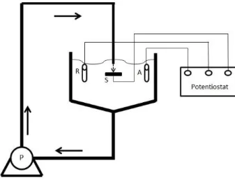
3 The erosion-corrosion testing utilised a recirculating slurry impingement test rig (Figure 1) of similar design as discussed previously [25]. The solid-liquid impingement testing was conducted with a 3.5%NaCl aqueous solution with 500µm spherical silica sand (1160Hv) and a sand concentration of 2.4g/l. The submerged jet had a velocity of 18m/s and the nozzle diameter was 3.8mm. The nozzle was consistently offset from the specimen surface by 5mm. The diameter of the test samples was 38mm. The testing temperature began at 16°C and rose to 27°C during the 1 hour test due to heat input from the pump. The sand size distribution was measured by sieving the sand incrementally by way of fine sieves; the sand size distribution is given in Table 1. Prior to testing, the non-nitrided specimens were ground on 220-1200 SiC grit papers. Mass loss measurements of the specimens were conducted with a mass balance with accuracy ±0.1mg. Surface topography was performed by using a non-contacting optical 3-D imaging system (Alicona Infinite Focus) with a wear scar depth accuracy of ±1µm and a wear scar volume accuracy of ±0.02mm³. The scatter bands (shown in Figures 5, 11 and 14) represent the maximum and minimum values found on a minimum of four test replicates. Macrohardness measurements were conducted with a Vickers hardness testing apparatus with a 5kgf load.
Figure 1: Schematic of erosion-corrosion test rig
Table 1: Sand Size distribution
Potentiodynamic scans were conducted to assess the electrochemical corrosion rates in static and in-situ solid-liquid impingement conditions. The potentiodynamic scans were conducted 15 minutes after the sample was submerged to allow for the free electrode potential, Ecorr, to stabilise. A Gill AC potentiostat was utilised for the potentiodynamic polarisation and cathodic protection tests. Platinum was used for the auxiliary electrode and Ag/AgCl was used as the reference electrode. The tests were conducted by shifting the initial potential either 20mV more positive (cathodic) or 20mV more negative (anodic) than the free electrode potential, hence ensuring that transition point would occur. Scans were then made 300mV more negative (cathodic) or 300mV more positive (anodic) at a
Particle Size (µm) Percentage (%) 2.5
250-420 18.4
421-500 50.7
501-600 23.3
4 sweep rate of 15mV/min. The chosen ranges were sufficient to evaluate corrosion current
measurements by way of Tafel extrapolation. The measured current densities were then used to evaluate the associated mass F L To conduct the polarisation tests, an electrically conductive wire was connected to the rear of the specimens, which were then cold mounted in epoxy resin. This ensured that only the tested surface was corroding. The cathodic protection (CP) experiments were focused at impingement angles at 90°
impingement angle only. For these the electrode potential was maintained at -800mV using an Ag/AgCl reference electrode at which potential back extrapolation of the anodic polarisation curves demonstrated that residual anodic reaction rates were negligible.
2.2 Materials
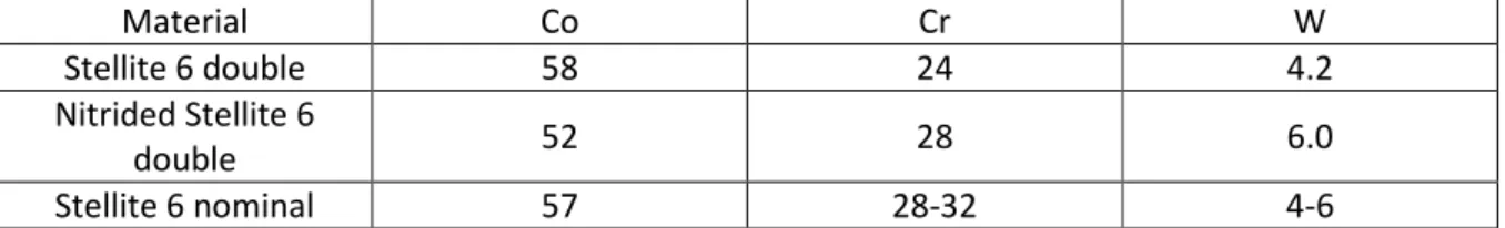
The materials studied were a Hot Wire Tungsten Inert Gas (HWTIG) Stellite 6 weld cladding single and double layers. The substrate used for the weld cladding was a low alloy steel (UNS G43400). Samples of both single and double weld cladding layers were also ammonia gas nitrided (hereafter referred to as Nit.) at 520°C for 72 hours. The chemical compositions (Table 2), determined by EDS, of the untreated and nitrided Stellite 6 weld deposits were found to be similar to a nominal
composition of Stellite 6.
Table 2: Some chemical compositional details (%wt) of the untreated and nitrided Stellite 6 double layer weld cladding
Material Co Cr W
Stellite 6 double 58 24 4.2
Nitrided Stellite 6
double 52 28 6.0
Stellite 6 nominal 57 28-32 4-6
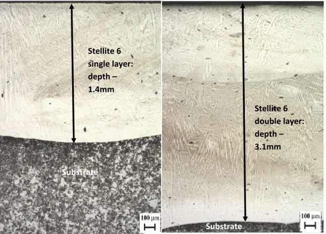
Cross sections of the single and double layer Stellite 6 and nitrided single Stellite 6 were polished and etched M F 2 and 3. Stellite 6 has a typical dendritic type
structure with a hypoeutectic microstructure. The microstructure contains primary Co-rich dendrites which are surrounded by Cr-rich eutectic carbides in a solid solution cobalt-rich matrix. The depths of the single and double layer weld as well as the depth of the nitride compound layer were measured using Image J software. The depths for the single and double layer cross sections were found to be 1.4mm and 3.1mm respectively. The depth of the nitride compound layer was found to be 27µm.
5
Figure 2: Microstructure of Stellite 6 single (left) and double (right)
Figure 3: Microstructure of Nitrided Stellite 6 Single layer
The macrohardness measurements of the surface of each test material are exhibited in Table 3. There was a considerable increase (56-70%) in hardness for both of the nitrided Stellite 6 weld claddings. Nitride Layer 0.75mm Co-rich matrix Cr-rich carbide
Stellite 6
single layer:
depth
1.4mm
Substrate
Substrate
Stellite 6
double layer:
depth
3.1mm
6 Table 3: Macrohardness measurements of each material
Material
Stellite 6 Single Stellite 6 Double Nit. Stellite 6 Single
Nit. Stellite 6 Double
Hardness (HV) 400 440 680 685
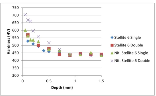
A microhardness profile was taken on each material to establish how the hardness altered with depth. Figure 4 demonstrates that there is a significant hardness increase for both the nitrided samples when compared to their untreated counterparts (80HV increase for single layer and 130HV increase for double layer). However, there is a sharp decrease in hardness with increasing depth. The nitrided Stellite 6 materials reached the core hardness of the untreated Stellite 6 at an approximate depth of 0.75mm which indicates the depth of the nitrided layer.
Figure 4: Microhardness profiles of each test material against surface depth
3. Results
3.1 Mass Loss
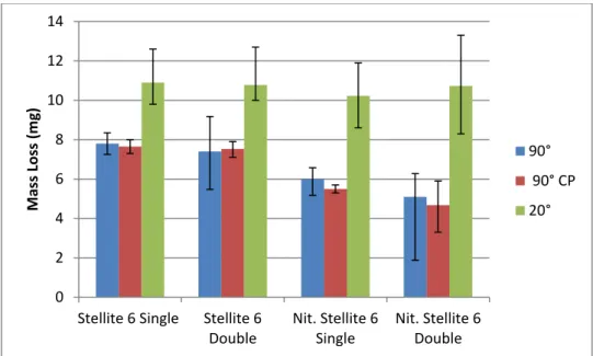
Figure 5 shows the total mass loss for each test material in 90°, 20° and cathodic protection (90° CP) test environments. The error bands represent the scatter between at least four replicates. The minimum scatter was found to be 0.4mg (Nit. Stellite 6 single - 90° CP) and the maximum scatter was found to be 5mg (Nit. Stellite 6 double - 20°). For tests with large scatters, additional tests were conducted. Mass losses were found to be greater (40-110%) in 20° tests than 90° tests for all materials. This is to be expected for materials that are behaving in a ductile rather than a brittle manner (See section 4. Discussion). The untreated and nitrided Stellite 6 weld claddings are composite materials (metal matrix with ceramic carbides/nitrides) and such materials are designed to display ductile behaviour. There was a decrease (23-31%) in average mass loss for the nitrided Stellite 6 samples at 90° impingement angle, however, when taking into account the experimental scatter, there was no clear distinction in mass loss with and without the application of cathodic protection. At 20° impingement angle, there was little difference in terms of mass loss to distinguish between the materials.
300 350 400 450 500 550 600 650 700 750 0 0.5 1 1.5 H a rd n e ss ( H V ) Depth (mm) Stellite 6 Single Stellite 6 Double Nit. Stellite 6 Single Nit. Stellite 6 Double
7 Figure 5: Mass loss of each material in both impingement angles and with cathodic protection
3.2 Polarisation tests
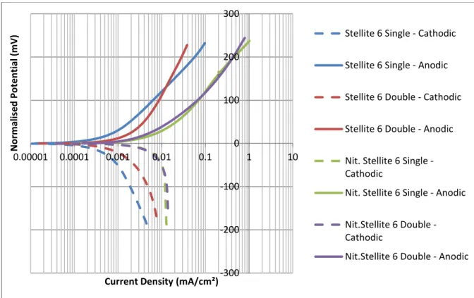
Anodic and cathodic polarisation scans were conducted for all test materials under static and solid-liquid conditions. The results in Figures 6 and 7 are presented with the electrode potentials commencing at zero (normalised). This was to facilitate simpler comparisons between each of the materials. The corrosion current densities are presented in Table 4.
In static conditions, Figure 6 demonstrates that both nitrided Stellite 6 weld claddings displayed rapidly increasing current density. The untreated Stellite 6 weld claddings demonstrated a significantly reduced (92-94%) corrosion activity compared to their nitrided counterparts.
Figure 7 demonstrates the polarisation scans for the test materials in solid-liquid conditions. All materials experienced increased corrosion rates in solid-liquid conditions compared to static conditions (65-373%). The nitrided Stellite 6 materials also exhibited increased (65-85%) active corrosion behaviour. The untreated Stellite 6 single layer weld cladding exhibited considerably greater corrosion rates (373%) than that in quiescent water due to the breakdown of the passive film caused by the presence of the silica sand in the fluid. The oscillating currents are archetypal of periodic de-passivation and re-passivation events.
Tafel extrapolation was utilised to generate the corrosion rates for all the test materials in both conditions. For the oscillating currents (maximum oscillating current density of 0.01mA/cm²) in solid-liquid conditions, a straight line was plotted running approximately through the centre of the oscillating currents. The resulting corrosion rates are exhibited in Table 4.
The free corrosion electrode potentials (Ecorr) for each test material in both static and solid-liquid test conditions are given in Table 5. In static conditions, the untreated steel displayed the most negative electrode potential whereas the less negative Ecorr of the nitrided steel was indicative of quite different corrosion behaviour. However, there was no obvious linkage with free electrode potential and corrosion current densities in solid-liquid conditions.
0 2 4 6 8 10 12 14
Stellite 6 Single Stellite 6 Double Nit. Stellite 6 Single Nit. Stellite 6 Double M a ss L o ss ( m g ) 90° 90° CP 20°
8 Figure 6: Anodic and cathodic polarisation of materials in static conditions
Figure 7: Anodic and cathodic polarisation of materials in solid-liquid conditions
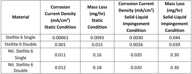
Table 4: Corrosion current densities and equivalent mass losses for each material
-300 -200 -100 0 100 200 300 0.00001N 0.0001 0.001 0.01 0.1 1 10 o rm a li se d P o te n ti a l (m V )
Current Density (mA/cm²)
Stellite 6 Single - Cathodic
Stellite 6 Single - Anodic
Stellite 6 Double - Cathodic
Stellite 6 Double - Anodic
Nit. Stellite 6 Single -Cathodic
Nit. Stellite 6 Single - Anodic
Nit.Stellite 6 Double -Cathodic
Nit.Stellite 6 Double - Anodic
-300 -200 -100 0 100 200 300 0.00001 0.0001 0.001 0.01 0.1 1 10 N o rm a li se d P o te n ti a l (m V )
Current Density (mA/cm²)
Stellite 6 Single - Cathodic
Stellite 6 Single - Anodic
Stellite 6 Double - Cathodic
Stellite 6 Double - Anodic
Nit.Stellite 6 Single -Cathodic
Nit.Stellite 6 Single - Anodic
Nit.Stellite 6 Double -Cathodic
Nit. Stellite 6 Double -Anodic
9 Material Corrosion Current Density (mA/cm2) Static Condition Mass Loss (mg/hr) Static Condition Corrosion Current Density (mA/cm2) Solid-Liquid Impingement Condition Mass Loss (mg/hr) Solid-Liquid Impingement Condition Stellite 6 Single 0.00063 0.0093 0.0030 0.044 Stellite 6 Double 0.001 0.015 0.0026 0.039 Nit. Stellite 6 Single 0.011 0.16 0.020 0.30 Nit. Stellite 6 Double 0.012 0.18 0.020 0.30
Table 5: Free corrosion potential (Ecorr) for all materials in each testing environment
Material Ecorr Static conditions (mV) E
corr Solid-liquid conditions (mV)
Stellite 6 Single -363 -472
Stellite 6 Double -518 -443
Nit. Stellite 6 Single -388 -346
Nit. Stellite 6 Double -415 -396
3.3 Surface topography
3.3.1 Wear Scar Depths
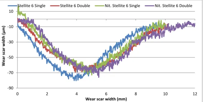
The wear scar depths were measured to assess the material behaviour in the direct impinged zone (DIZ - zone directly beneath the nozzle). The wear scar depths for each material were compared for each testing environment - 90° free erosion-corrosion (FEC), 90° CP and 20° FEC. The maximum wear scar depth was measured and recorded for each material. Figure 8 shows the post-test images of a nitrided Stellite 6 single layer weld cladding for both 20° and 90° impingement tests. Figures 9 and 10 compare the wear scar depth profiles for each material for 90° and 20° impingement in FEC test conditions. As might be expected, the wear scars are larger in surface area after attack at the oblique angle of 20°.
10 Figure 8: Post-test images of Nitrided Stellite 6 single layer: after 20° impingement (left) and after 90° impingement
(right)
Figure 9: Wear scar depth comparison for each material in 90° FEC test conditions
-90 -80 -70 -60 -50 -40 -30 -20 -10 0 10 0 1 2 3 4 W e a r S ca r D e p th ( µ m )
Wear Scar Width (mm)
11 Figure 10: Wear scar depth comparison for each test material in 20° FEC test conditions
Figure 11 illustrates the average wear scar depths for all of the tested materials in each of the test environments including the effect of applied cathodic protection (CP). The minimum scatter was found to be 2µm (Stellite 6 single - 90°CP) and the maximum scatter was found to be 18µm (Nit. Stellite 6 double - 90°).The nitrided Stellite 6 double layer weld cladding demonstrated the highest average wear scar depth in the 90° FEC test environment. There was a reduction (19%) in wear scar depth for the Stellite 6 single layer weld cladding when CP was applied; however, there was no apparent reduction for the Stellite 6 double layer weld cladding. There was also a significant reduction (40-51%) in wear scar depths for both nitrided Stellite 6 weld claddings when CP was applied. The nitrided Stellite 6 double layer weld cladding showed the lowest wear scar depth in the 20° FEC test environment. The other materials exhibited similar wear scar depths in the 20°
impingement test.
Figure 11: Wear scar depth measurements for each of the tested materials in each of the testing environments
-90 -70 -50 -30 -10 10 0 2 4 6 8 10 12 W e a r sc a r w id th ( µ m )
Wear scar width (mm)
Stellite 6 Single Stellite 6 Double Nit. Stellite 6 Single Nit. Stellite 6 Double
0 20 40 60 80 100 120 Stellite 6 Single Stellite 6 Double Nit. Stellite 6 Single Nit. Stellite 6 Double W e a r S ca r D e p th ( µ m ) 90° 90° CP 20°
12 3.3.2 Volume Losses
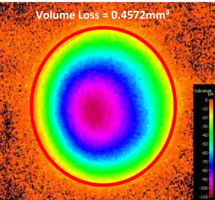
Volume loss measurements in the wear scar were also recorded to provide further analysis of the damage occurring in the DIZ. Figure 12 displays the volume loss measurement for a nitrided Stellite 6 double layer weld cladding after a 90° FEC test. Figure 12 shows a volume loss measurement for a Stellite 6 single layer weld cladding after a 20° FEC test. The volume loss measurements were taken within the superimposed red rings which represent the zones directly underneath the impinging fluid.
Figure 12: Volume loss measurement in the DIZ of a nitrided Stellite 6 double layer weld cladding at 90° FEC test conditions
Figure 13: Volume loss measurement in the DIZ of a Stellite 6 single layer weld cladding at 20° FEC test conditions
The volume loss measurements, for each test material after experiments at 20° and 90° under FEC conditions are illustrated in Figure 14. The minimum scatter was found to be 0.009mm³ (Stellite 6
Volume Loss = 0.4572mm³
13 single - 90°) and the maximum scatter was found to be 0.28mm³ (Nit. Stellite 6 double - 20°). Whilst comparison of volume loss in the wear scar between 90° and 20° impingement was complicated somewhat by the relatively large scatter for the 20° cases, there was a general trend of increased (5-79%) wear scar volume loss at 20° compared to 90° impingement. This was unlike the trends in wear scar depth. It also, appeared that there was a decrease (18-34%) in average volume loss for both nitrided Stellite 6 weld claddings compared with their untreated Stellite 6 counterparts at 20° impingement.
Figure 14: Volume losses in wear scar for each test material in 20° and 90° impingement
3.3.2 Volumetric Analysis
A volumetric analysis technique [24] was also utilised to provide further evaluation of the inherent corrosive wear resistance of the tested materials. Mass losses for the two distinct wear zones (directly impinged zone DIZ and the outer area OA ) can be obtained by converting the measured DIZ volume losses to mass losses via the known density (8.4 g/cm³) of Stellite 6 followed by subtraction from the measured total mass loss:
Eq. (1)
However, it should be noted that, whilst this calculation is valid and yields extremely useful additional information for experiments conducted at 90° impingement, it cannot be utilised for specimens subjected to 20° impingement on account of the substantially non-uniform material loss in different regions of the outer area see Figure 8. It is clear that the damage is greater
downstream of the 20° impinging jet than in the area surrounding the 90° impinging jet. These differences are clearly linked with the lateral velocity with regard to which some modelling work has indicated that damage is minimal between velocities of 2-4m/s [26].
Figure 15 illustrates the discretisation of the mass losses in the two wear regions at 90° FEC test conditions. The mass losses in the DIZ were similar for all materials; however, there was a significant reduction (33-41%) in mass losses in the OA for the nitrided Stellite 6 weld claddings when
0 0.1 0.2 0.3 0.4 0.5 0.6 0.7 0.8
Stellite 6 Single Stellite 6 Double Nit. Stellite 6 Single Nit. Stellite 6 Double V o lu m e L o ss ( m m ³) 90° 20°
14 compared to the untreated Stellite 6 weld claddings. The lowest mass loss in the OA was recorded by the nitrided Stellite 6 double layer weld cladding.
Figure 15: Breakdown of the mass losses in the two distinct wear regions in 90° FEC test conditions
Figure 16 demonstrates the breakdown of the mass losses in the two wear regions for each material in 20° FEC test conditions. The nitrided Stellite 6 weld claddings showed lower mass losses in the DIZ when compared with the untreated Stellite 6 weld claddings. The nitrided Stellite 6 double layer weld cladding illustrated the lowest mass loss in the DIZ. A very interesting feature of Figures 15 and 16 is how the trends of the ML (DIZ) at 20° impingement mirrors the ML (OA) at 90° impingement. This aspect is given further attention in the Discussion section.
7.8 3.0 4.7 7.4 2.8 4.6 6.0 3.0 3.1 5.1 3.4 1.8 0 1 2 3 4 5 6 7 8 9 TML 90° ML 90° (DIZ) ML 90° (OA) M a ss L o ss ( m g )
15 Figure 16: The total mass loss and mass loss in the wear scar for 20° impingement FEC test conditions
4. Discussion
From the microhardness profiles in Figure 4 and the macrohardness values in Table 3, there is a clear increase (56-70%) in hardness which has been caused by the nitriding process. This increase in hardness is a result of the nitrides which have been formed on the surface of the Stellite 6 weld claddings. Although the nitriding process was successful in surface hardening the Stellite 6 weld claddings, the hardness was significantly less than that of nitrided steels which have been assessed in past studies [15,16,18]. However, from the same nitriding duration (72 hours) a nitride compound layer depth (27µm) and a hardened depth of approximately 0.6mm was found for the nitrided Stellite 6 double layer weld cladding which was similar to that of a nitrided 905M39 steel [16]. Another interesting finding was the apparent increase in hardness near the surface of both
untreated single and double layer Stellite 6 weld claddings. This may be caused by the faster cooling rate at the surface, which has resulted in a finer microstructure and hence a higher hardness.
From the total mass losses (Figure 5) it can be seen that all materials have a greater mass loss at 20° impingement than that of 90°. It can be seen that, even taken into account the scatter between replicate tests, all materials demonstrate greater mass losses at 20° impingement. This is indicative of materials which are exhibiting a ductile behaviour as would be expected from a composite metal matrix material comprising chromium carbides/nitrides particles in a tough metal matrix. This is in line with the classical notion of erosive ductile material behaviour proposed by Finnie [27], despite the significant increase in hardness as a result of the nitriding process. This would suggest that the nitriding process does not provide any benefit to the Stellite 6 weld claddings in 20° impingement erosion corrosion conditions. However, this conclusion would be misleading as there is a significant reduction in both wear scar depth (21%) and volume loss (20° impingement up to 34% reduction) for the nitrided Stellite 6 double layer weld cladding when compared to its non-nitrided counterpart.
Polarisation scans (Figures 6 and 7) demonstrate that nitriding the Stellite 6 weld claddings had a detrimental effect to their corrosion resistance. Both nitrided weld claddings illustrated active
10.9 5.1 10.8 5.0 10.2 4.2 10.7 3.3 0 2 4 6 8 10 12 TML 20° ML 20° (DIZ) M a ss L o ss ( m g )
16 behaviour in both static and solid/liquid testing conditions. This poor corrosion resistance has been observed in past studies [19-20] and is likely to be associated with the reduction in passive film integrity by the preferential formation of chromium nitrides. The Stellite 6 weld claddings
demonstrated some passivation/de-passivation behaviour under solid/liquid conditions as shown by the slight oscillations in Figure 7. It should be noted that the mass loss due to corrosion (Table 4) for the nitrided weld claddings in solid/liquid conditions was only 0.3mg, which is less than 6% of the total mass loss.
When taking into consideration the scatter between individual replicates, Figure 11 shows clearly that there was a significant reduction (up to 51% calculated with average values) in wear scar depth for the nitrided Stellite 6 weld claddings when cathodic protection was applied, which highlights their relatively poor corrosion resistance. This indicates that a significant amount of the damage was attributed to corrosion and synergy, however, the majority of the damage was erosion. Cathodic protection had little to no benefit to the non-nitrided Stellite 6 weld claddings as the dominant wear mechanism was erosion. However, there was a noticeable reduction (19%) in the wear scar depth of the Stellite 6 single layer weld cladding when cathodic protection was applied.
The mass losses in the two distinct zones provided further insight into the corrosive wear behaviour of the four materials. Although there was very little difference between the materials in the DIZ in 90° impingement, there was a significant reduction (up to 41%) of mass loss in the OA of the nitrided Stellite 6 weld claddings compared to the non-nitrided Stellite 6 weld claddings. As the mechanical damage in the OA is sliding abrasion[24,27-28], this improvement can be attributed to the increase in hardness associated with the production of chromium nitrides during the nitriding process, which improves the sliding abrasion resistance of the materials [29-30]. However, this benefit of the nitriding treatment did not extend to the behaviour in the DIZ where different erosion mechanisms are occurring.
The volumetric analysis technique represents a clear example of the benefits associated with extending the evaluation of erosion-corrosion impingement tests to include the measurement of wear scar volume [24]. In other words, the extended analysis strategy enables the trends shown by total mass loss measurements alone, to be more appropriately ascribed to different wear
mechanisms.
The calculated mass losses in the wear scar of specimens after impingement at 20° provided a good linkage with the outer area mass losses of specimens tested in 90° impingement. Thus the relative performance of nitrided and untreated Stellite 6 were mirrored between the wear scar at low angle (20°), Figure 15, and the outer, low angle, region of the specimens after tests at 90° impingement, Figure 14.
5. Conclusions
1. The nitriding process was found to significantly increase the hardness of the Stellite 6 weld cladding from approximately 400HV to 680HV. The hardness gradually declined with depth until the bulk hardness of the weld cladding was reached at 0.6mm depth.
2. The nitriding process was found to be detrimental to the corrosion resistance of the Stellite 6 weld cladding in both static and solid/liquid impingement conditions.
17 3. At 90° impingement, the nitrided Stellite 6 weld claddings demonstrated smaller total mass
loss than the non-nitrided Stellite 6 weld claddings. The post-test analysis procedure showed that this improvement was on the low-angle (outer) wear region and the improvements are mainly attributed to their increase in hardness which resulted in increased sliding abrasion resistance. In contrast, nitriding yielded no benefits under 90° direct impingement
conditions.
4. Cathodic protection significantly reduced the wear scar depths and volume losses of the nitrided Stellite 6 weld claddings but was less effective for the non-nitrided Stellite 6 weld claddings.
Acknowledgements
The authors would like to acknowledge the support for this study, which was provided by the Weir Group PLC (WARC2011SAA1, 2011) via its establishment of the Weir Advanced Research Centre (WARC) at the University of Strathclyde.
References
[1] C I W “ -liner wear: Comparison of
Wear, vol. 250 251, no. PART 1, pp. 81 87, 2001.
[2] C I W G C B E P
1: Side- Wear, vol. 242, no. 1 2, pp. 140 146, 2000.
[3] M J R J L A E C P M
“ Nace Int. Corros. 2007 Conf.
expo, no. 7685, pp. 1 15.
[4] M R A N D hanisms of Co-based alloy and WC metal matrix
Wear, vol. 255, no. 7 12, pp. 1143 1156, 2003.
[5] A N T H C -grade alloy behaviour in severe
erosion-Wear, vol. 233 235, pp. 596 607, 1999.
[6] A N M R T H A G M C -base alloy in
liquid Wear, vol. 238, pp. 138 150, 2000.
[7] A N H X M R C -corrosion behavior of a Co-based
alloy and a Ni- Corrosion, no. 149, p. Paper No.00031, 2000.
[8] U M A N M W C -based alloys their
effects on erosion corrosion resistance Wear, vol. 259, no. 1 6, pp. 219 229, 2005.
[9] M X Y J B C W Y X W W- or
“ Mater. Sci. Eng. A, vol. 407, no. 1 2, pp. 234 244, 2005. [10] H. Yu, R A H D V L “ D I M P
Alloying Element Content on the Tribomechanical Properties of Cobalt-B A J. Tribol., vol. 131, no. 1, p. 11601, 2009.
[11] U M A N C the performance of HIPed and Cast Stellite 6 alloy in liquid Wear, vol. 255, no. 1 6, pp. 181 194, 2003.
18 [12] J. R. Davis, Surface Hardening of Steels. 2002.
[13] B P J V V L W hardened, conventional plasma nitrided and pulse plasma nitrided AISI 4140 steel in dry sliding
Wear, vol. 232, no. 2, pp. 231 242, 1999.
[14] B “ M V A A
HVOF coat T Wear, vol. 249, no. 5 6, pp. 354 360, 2001.
[15] B P F M V L J V I
tool steels through combination of deep-cryogenic treatment and plasm Wear, vol. 288, pp. 88 93, 2012.
[16] G. Karafyllias, F. Brownlie, L. Giourntas, T. Hodgkiess, A. M. Galloway, and A. Pearson,
C T T , 2015. [17] B. S. M V A A Wear, vol. 253, pp. 650 661, 2002. [18] H D P Y Q X Y L R J L I ion-corrosion resistance of AISI 316 austenitic stainless steel by low- N C Mater. Sci. Eng. A, vol. 431, no. 1 2, pp. 137 145, 2006.
[19] J L “ M R C C ed body fluid after Surf. Coatings Technol., vol. 204, no. 18 19, pp. 3043 3046, 2010.
[20] J L C D J A G C B “ M C C C alloy after nitrogen plasma immersion ion implan Surf. Coatings Technol., vol. 205, no. 8 9, pp. 3043 3049, 2011.
[21] G T B K “ E corrosion of 304L Wear, vol. 240, no. 1 2, pp. 80 94, 2000.
[22] D. A. López, J. P. C J R C A T A P T E velocity and impact angle on the corrosion AI“I AI“I Wear, vol. 259, no. 1 6, pp. 118 124, 2005.
[23] N. Andrews, L. Giourntas, A. . Gallow A P E erosion- “ ““ Wear, vol. 320. pp. 143 151, 2014.
[24] L G T H A M G E
corrosive wear of engineering Wear, vol. 338 339, pp. 155 163, 2015.
[25] L G T H A M G C corrosion
Wear, vol. 332 333, pp. 1051 1058, 2015.
[26] A G N K A N J F F A
Wear, vol. 267, no. 11, pp. 1935 1944, 2009.
[27] I F “ Wear, vol. 19, no. 1, pp. 81 90, 1972.
19
[28] A G N K A N J F F N G A
Wear,
vol. 271, no. 5 6, pp. 712 719, 2011.
[29] L G F B G K T H A M G E
23rd International conference on Fluid Sealing,
2016, pp. 171 182.
[30] R J L “ K Y K F D “