Effect of fiber laser parameters on laser welded
AZ31B Magnesium alloys
Naqiuddin Mat Salleh1, Mahadzir Ishak1,*, and Fadhlur Rahman Romlay1 1
Faculty of Mechanical Engineering, Universiti Malaysia Pahang, 26600 Pekan, Malaysia.
Abstract. Recently, the usage of Magnesium (Mg) alloys has been hugely applied in the industrial application such as in automotive, marine, and electronic due to its advantages of recyclability and lightweight. This alloys required low heat input to be weld since it is easily evaporated due to the Magnesium Oxide (MgO) at the surface and it also possesses lower melting point compared to steel. Laser welding is more convenient to weld Mg alloys due to its high power and lower heat input. AZ31B was selected since it has strong mechanical properties among others Mg alloys due to the major alloying elements; Aluminium (Al) and Zinc (Zn). Low power fiber laser machine with wavelength of 900 nm was used in this experiment. The intention of this work was to investigate the effect of low power fiber laser parameters and effect of shielding gas on weld penetration and microstructure. Another aim in this work was to produce the joint for this thin sheets metal. Penetration depth and microstructure evaluation were emphasized in the analysis section. Bead-on-Plate (BOP) and laser lap welding was conducted on AZ31B with thicknesses of 1.0 mm and 0.6 mm for feasibility study using pulsed wave (PW) mode. Defocusing features was used in order to find better focal position, which has less occurrence of evaporation (underfill). The effect of different angle of irradiation was also investigated. Two types of shielding gases, Argon (Ar) and Nitrogen (N2) were used in order to study the effect of shielding gas. Lastly, the effect of pulsed energy on penetration types and depth of BOP welded samples was investigated. Focus point was found at focal length of 156 mm with 393.75 µm. For BOP experiment, higher pulsed energy used contributes to melt through defect. Meanwhile, Ns shielding gas proved to be better shielding gas in laser welding the AZ31B. Higher angle of irradiation could reduce the underfill defect. Fillet Lap joint of similar metal was successfully done where 2.0 J of pulsed energy reveals better weld joint compared to 2.4 J.
1 Introduction
In mechanical engineering field, joining product has become a great demand where it is important to make two or more of similar or different parts to become one product with good characteristics. There have several types of joining especially in mechanical engineering fields such as bolt and fasteners, adhesive, solder, rivet, and welding method.
*
In metal joining, welding method was usually selected to produce strong permanent joints compared to others. However, laser welding promising a unique ways compared to the conventional welding that have been applied industries long before. As a means known in industrial especially in manufacturing line, fibre laser welding was proved to be best among the laser welding method in terms of saving overall operating cost, easily automated, and allows higher welding speed with excellent weld bead [1]. This process already becomes an important manufacturing process especially in joining metals due to its advantages as a bonding process. The applications of laser welding have been discussed by G.V. Moskvitin, et., al, [2] where the laser welding application can produce a powerful laser beam, concentrated heat source, and allowing to obtain deep and narrow penetration for the high speed process. Laser light is monochromatic and collimated (single wavelength and parallel), so that beam can be focused to very small diameters where the photon can produce enough laser energy to melt the metal in short time.
For past few years, there has been tremendous usage of fibre laser in welding metals such as steels, aluminium alloys, magnesium alloys, and titanium alloys [3-9]. Among of this metals, Magnesium alloys was the attractive metal in automotive, aerospace, and marine industries due to their lower density and high specific strength with high corrosion resistance [10]. Magnesium is the sixth most abundant element on Earth’s surface and represents about 2.5% of its composition [11]. This non-ferrous metal have attracted huge attraction recently as a new kind of degradable biomaterial where it has advantages of density almost same to that of human bone [12]. This means that this material was having a good usage although to human being. In aerospace, magnesium alloys also was highly recommended as it has lightest density among other materials and they are good for engineering application by replacing engineering plastics since magnesium alloys are stiffer, more recyclable, and less costly to produce [13]. The trending laser welding on magnesium alloys was attracted on AZ31B magnesium alloys where it has the properties of Medium-strength alloy, weldable, and good formability [13]. In recent years, AZ31B was successfully welded using laser welding method by some researcher. AZ31B-H24 wrought magnesium alloys with thickness of 1.7 mm was used in the studies of effect of shielding gas and laser wavelength using CO2laser type and Nd:YAG laser type for BOP test [14]. Nd:YAG laser was similarly with fibre laser since the laser beam was conducted by the fibre core with same wavelength. However, maximum 2 kW average power in continuous wave (CW) mode was needed to weld 1.7 mm thick AZ31B. Fibre laser welding with 4 kW using two weld pass method was successfully done to 1.5 mm thick of AZ31B by applying overlapped joint [7] where also CW welding mode was used with the 1 kW average power. However, they still need to use laser average power up to 3 kW in order to perform preheating (first pass). AZ31B was then successfully joined using Nd:YAG laser welding types with fillet lap configuration [8]. They focused on pulsed wave (PW) laser mode with pulsed energy of 1.8 Joules to make similar fillet lap joint of 0.3 mm thick AZ31B. So far, there was still lack of research in laser welding of thin sheets AZ31B magnesium alloys where these products could become a huge significant in many industries especially for transportation (automotive) since it will increase the percentage of fuel economy in future.
The intention of this present work carried out was to find out the possible laser welding behavior to obtain sound weld of thin sheets (0.6 mm thick) AZ31B using low power fibre laser welding machine with 200 W average powers with 900 – 1200 nm wavelength. Pulsed wave (PW) was more focused in this experimental work and the important parameters which plays major roles were laser pulsed energy, types of shielding gas, and angle of irradiation. The effects of these parameters were investigated in order to investigate the effect toward weld penetration and its microstructure. As well, an attempt to produce similar joint for AZ31B magnesium alloys have been conducted where the parameters were selected form the BOP welded result.
2 Experimental setup
The experimental works start with finding the focus points on AZ31B magnesium alloys surface since different metals produce different heat absorptions when subjected to the laser beams since different heat transfer, Q occurred compared with other metals. Material used in this research works was thin sheet AZ31B with thickness range from 0.6 to 1.0 mm. One laser spot was shot on the metals surface using the range of pulsed power from 80 to 100 % (1.6 – 2.0 kW) with wavelength of 900 nm. The focal lengths used were ranged from 150 to 160 mm. Beam diameter from the laser spot was measured at each focal length. Next, BOP welding was conducted on 1.0 mm thickness of AZ31B where the pulsed energy, Ep was studied. In this work, 0 degree angle of irradiation (AOI) with the absent of shielding gas were used. The effect of pulsed energy was studied based on the macrostructure of the weld cross section. Calculation for laser pulsed energy was made based on Eq. (1):
Ep =Pp × ∆t (1)
where Pp is peak power in Watt (W) , and ∆t is pulse width in milliseconds (ms). After that, AZ31B samples was BOP welded using two different types of shielding gas which were Argon (Ar), and Nitrogen (N2) gas with flow rates of 25 L/min. Previous researcher found that N2 helps preventing the formation of pores in the WZ in non-ferrous metal compared to using Ar gas despite being use angle of irradiation up to 40̊ inclination [15]. Another motivation using N2gas is it was inflammable gas which can reacts with high performance since AZ31B is a flammable metal. The parameters such as pulsed energy (1.7 J), welding speed (3 mm/s), angle of irradiation (3̊), was used at defocused position of +26 mm (FL= 130 mm). The comparison between the welded samples cross section was studied and defect in the microstructure was inspected in this experiment. Next to that, an experiment to study the effect of angle of irradiation (AOI) also has been operated. Using same parameter as before, range of AOI selected was 1̊ to 5̊. AZ31B sheets with thickness of 1.0 mm were used in this experiment with N2shielding gas at flow rate 25 L/min. Figure 1 shows the schematic of depth measurement at the weld cross-section. From the cross section, the underfill defect and weld depth were measured for each sample from different AOI.
After the BOP welds have been performed, an attempt on joining the thin sheet metals (AZ31B) of 0.6 mm thick have been done. Fillet lap joint configuration has been conducted using pulsed wave (PW) mode with N2shielding gas at flow rate 25 L/min. Figure 2 shows the experimental setup for fillet lap joint. As shown in Figure 2(a), AOI used in this fillet lap weld was 3̊ with the angle of shielding gas nozzle at 30̊. From the schematic view in Figure 2(b), this preliminary test used defocused position at +26 mm from the focused point which at beam diameter of 524 µm. The centre of beam was focused on upper sheet, meanwhile another half of the beam diameter focused on lower sheet. Primarily, single fillet lap joint was made and the parameters selected was 2.0 and 2.4 J of pulsed energy with controlled parameters of welding speed and angle of irradiation with the value of 3 mm/s and 3̊, respectively. Pulsed width used was 2 ms with the Pulsed Repetition Rate of 60 HZ also was applied. At 2.0 J, 1000 Watt (50%) of laser peak power was used. Meanwhile, 1200 W (60%) of peak power used for pulsed energy of 2.4 J.
(a)
(b)
Fig. 2. Experimental setup for fillet lap welding (a) real view (b) schematic view.
3 Results and discussion
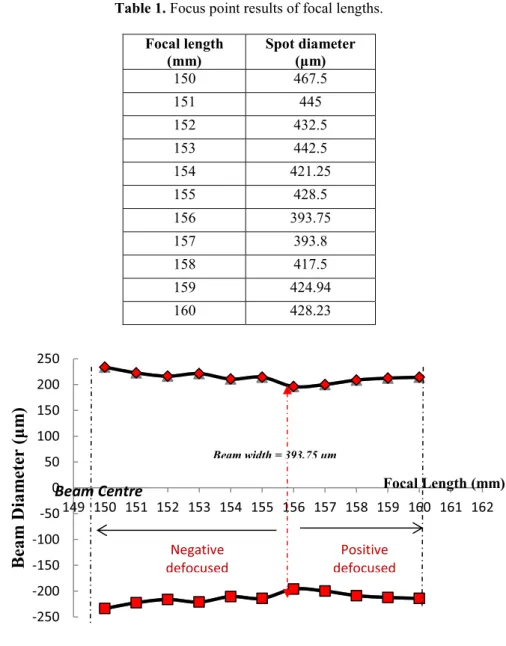
3.1 Focus point experimentTable 1 shows the result in finding smallest beam diameter which represents the focus points of laser beam on AZ31B magnesium alloys surface. From the tabulated data, a graph of spot diameter versus focal length with the range of 1 mm between them was constructed as shown in Figure 3. From the graph below, the focus point for material AZ31B was at focal length, FL = 156 mm with beam diameter of 393.75 µm. So that, the focused point is set to 0 (FP= 0) at focal length 156 mm. It was concluded that the focus point of the laser beam on AZ31B was at FL = 156 mm with approximately 400 µm of beam width.
Table 1. Focus point results of focal lengths. Focal length (mm) Spot diameter (μm) 150 467.5 151 445 152 432.5 153 442.5 154 421.25 155 428.5 156 393.75 157 393.8 158 417.5 159 424.94 160 428.23
Fig. 3. Graph of beam diameter versus focal length.
3.2 Bead-on-plate (BOP) experiment
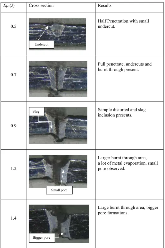
Firstly, the results from the investigation of different usage of pulsed energy were discussed. It was shown that increasing in pulsed energy contributes to the burnt through defects since metals are evaporated with high energy absorption in investigating the pulsed energy without using shielding gas and angle of irradiation.
-250 -200 -150 -100 -50 0 50 100 150 200 250 149 150 151 152 153 154 155 156 157 158 159 160 161 162
Beam
Diam
ete
r
(μ
m
)
Focal Length (mm)Beam Centre
Negative defocused Positive defocused Beam width = 393.75 µmEp,(J) Cross section Results
0.5
Half Penetration with small undercut.
0.7
Full penetrate, undercuts and burnt through present.
0.9
Sample distorted and slag inclusion presents.
1.2
Larger burnt through area, a lot of metal evaporation, small pore observed.
1.4
Large burnt through area, bigger pore formations.
Fig. 4. BOP welded AZ31B with different pulsed energy.
Small pore Slag
Undercut
From figure above, it was found that AZ31B was evaporated with the increasing pulsed energy. This factors also was caused by zero usages of shielding gas where the metals was easily evaporated due to this metals was easily burned. From observation, only 0.5 J pulsed energy shows better weld result compared to others weld products with small undercut defects. For sample with 0.9 J pulsed energy, slag inclusion presented in the weld due to the improper samples cleaning before the experiments was conducted. Porosity was observed starting from the pulsed energy of 1.2 J and became bigger at 1.4 J. Pores presented in the weld due to the high rates of burning factors during welding process. For the different shielding gas experiment, Figure 5 shows the comparison between samples welded with Ar and N2 shielding gas with same value of flow rates. It was observed that sample which laser welded with Ar gas produces porosity in the weld region while pores do not present in the weld region to sample that welded with N2 gas. However, both samples experienced hot crack at the centre of weld zone (WZ) due to the rapid cooling after being laser welded. Due to the same laser energy absorption on the metal surfaces, underfill defect still showed up due to the metal evaporations occurred during welding process.
(a) (b)
(c)
Fig. 5. Cross section of sample welded with (a) Argon (b) Nitrogen (c) welded zone of
sample welded with Ar, 50 X magnifications.
As mentioned in methods section, an experiment to study the effect of inclination angle of irradiation (AOI) also has been operated. Using same parameter as before, range of AOI selected was 1 ̊ to 5 ̊.
Underfill
Cracks
AOI, ( ̊ ) Cross section microstructure Results 1 Weld Depth= 0.333 mm Underfill depth = 0.143 mm 2 Weld Depth= 0.326 mm Underfill depth = 0.095 mm 3 Weld Depth= 0.160 mm Underfill depth = 0.00 mm 4 Weld Depth= 0.155 mm Underfill depth = 0.00 mm 5 Weld Depth= 0.150 mm Underfill depth = 0.00 mm
Fig. 6. Microstructure of BOP welded AZ31B with different AOI.
Figure 6 above shows the microstructure with 5 x magnifications for each AOI used. It was observed that the smallest angle of irradiation, the underfill depth became more. It was observed that when using the AOI bigger than 3̊, the underfill defect was successfully eliminated although the penetration depth was reduced by 0.05 mm. Porosity also was not observed in the microstructure as N2 gas was used. Nitrogen was proved to be better selection as the shielding gas to weld Mg alloys compared to Argon gas.
Underfill
3.3 Lap joint of thin sheet AZ31B
Similar weld of AZ31B was successfully welded with fillet lap joint method where the centre of the laser beam with defocused position was used to produce the weld. Figure 7 shows the macrostructure image of fillet lap joint with different value of pulsed energy. From this figure, it was observed that fillet lap weld when using pulsed energy at 2.0 J produced better weld joint compared to 2.4 J pulsed energy. It was proved that 2.0 J was suitable to make fillet weld joint at defocused of +26 mm. Crack was not observed at the FZ for sample welded with 2.0 J compared to that welded with 2.4 J. Figure 8 shows the microstructures of a small portion in sample from Figure 7 (a).
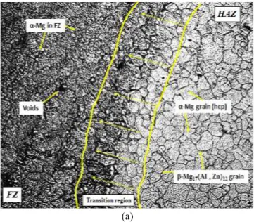
From Figure 8 (a), it was observed that the grain boundaries were transform into smaller equiaxed dendritic grains where it represents the α-Mg grain structure. In heat affected zone (HAZ) region, the hexagonal structures have bigger grain size with 16.5 µm compared to its structure in the unaffected BM with 8.0 µm as shown in Figure 9 (b) where there was a double increments due to more heat absorbs since HAZ is a region of base material near the interface to the fusion zone. From previous research, the basic shape of BM in AZ31B was hexagonal closely packed (hcp) with the α-Mg and β-phase of Mg17(Al,Zn)12precipitates where α-Mg grain size was about 7.7 μm. Meanwhile, β-phase of Mg17(Al,Zn)12ellipsoidal particle with maximum length of 200 nm [16].Typically, β-Mg17(Al,Zn)12precipitates were coarsening with the increasing grain size of α-Mg which affected by the heat input. From Figure 8 (a) also, it was found that fusion zone (FZ) was characterized by α-Mg grain phase but with smaller grain sizes with value of 4.2 µm. In FZ also, voids presented due to insufficient shielding gas flow rates supplied during laser welding process.
(a)
(b)
(a)
(b)
Fig. 8. Microstructure image of (a) FZ and HAZ (b) unaffected BM.
4 Conclusions
The influences of low power fibre laser welding parameters, such as pulsed energy, angle of irradiation, and types of shielding gas, on the weld penetration and microstructure of BOP and fillet lap welding of AZ31B magnesium alloys with thickness of 0.6 mm using pulsed low power fibre laser have been investigated. The following conclusions can be drawn for this present research. Firstly, lower pulsed energy could give better result in making the weld joints. So that, low power laser machine can be used to weld this thin sheets AZ31B. Secondly, increasing the angle of irradiation (AOI) can eliminates the underfill defects in weld joint since it reduce the metal evaporation during laser welding processes. Thirdly, fusion zone (FZ) was characterized with smaller α-Mg grain structure which relatively smaller compared to BM where at this region, the grain also consists of
β-phase of Mg17(Al,Zn)12 precipitates which the grain size relatively higher than that of α-Mg
grain. Lastly, pulsed wave (PW) was successfully created the fillet lap joint of 0.6 mm thick of AZ31B with fewer defects observed. In addition, this joint could be improved with the aid of design of experiment (DOE) such as response surface methods (RSM).
The author would like to thank the technical staff of Universiti Malaysia Pahang for all of the work by providing laboratory facilities within which the experiments were conducted. Also, financial support by the Ministry of Education through Universiti Malaysia Pahang for research grant RDU140118 is gratefully acknowledged.
References
1. E. Assunção, L. Quintino, and R. Miranda, "Comparative study of laser welding in tailor blanks for the automotive industry," The International Journal of Advanced Manufacturing Technology, vol. 49, pp. 123-131, 2009.
2. G. V. Moskvitin, A. N. Polyakov, and E. M. Birger, "Application of laser welding methods in industrial production," Welding International, vol. 27, pp. 572-580, 2013. 3. J. Ahn, L. Chen, C. M. Davies, and J. P. Dear, "Parametric optimisation and
microstructural analysis on high power Yb-fibre laser welding of Ti–6Al–4V," Optics and Lasers in Engineering, vol. 86, pp. 156-171, 2016.
4. R. Lai, Y. Cai, Y. Wu, F. Li, and X. Hua, "Influence of absorbed nitrogen on microstructure and corrosion resistance of 2205 duplex stainless steel joint processed by fiber laser welding," Journal of Materials Processing Technology, vol. 231, pp. 397-405, 2016.
5. I. Bunaziv, O. M. Akselsen, A. Salminen, and A. Unt, "Fiber laser-MIG hybrid welding of 5mm 5083 aluminum alloy," Journal of Materials Processing Technology, vol. 233, pp. 107-114, 2016.
6. M. Harooni, B. Carlson, and R. Kovacevic, "Detection of defects in laser welding of AZ31B magnesium alloy in zero-gap lap joint configuration by a real-time spectroscopic analysis," Optics and Lasers in Engineering, vol. 56, pp. 54-66, 2014. 7. M. Harooni, J. Ma, B. Carlson, and R. Kovacevic, "Two-pass laser welding of AZ31B
magnesium alloy," Journal of Materials Processing Technology, vol. 216, pp. 114-122, 2015.
8. M. Ishak, K. Yamasaki, and K. Maekawa, "Lap Fillet Welding of Thin Sheet AZ31 Magnesium Alloy with Pulsed Nd:YAG Laser," Journal of Solid Mechanics and Materials Engineering, vol. 3, pp. 1045-1056, 2009.
9. M. Ishak, K. Yamasaki, and K. Maekawa, "Lap Fillet Laser Welding of AZ31B Thin Sheet Magnesium Alloy using Silver Nanoparticles," Journal of Solid Mechanics and Materials Engineering, vol. 4, pp. 51-62, 2010.
10. Z. D.T. YAN Yong, QIU Cheng, ZHANG Wen, "Dissimilar friction stir welding between 5052 aluminum alloy and AZ31 magnesium alloy," Transaction of Nonferrous Metal Society China, vol. 20, pp. 619-623, 2010.
11. X. Cao, W. Wallace, J. P. Immarigeon, and C. Poon, "Research and Progress in Laser Welding of Wrought Aluminum Alloys. II. Metallurgical Microstructures, Defects, and Mechanical Properties," Materials and Manufacturing Processes, vol. 18, pp. 23-49, 2003.
12. X.-N. Gu and Y.-F. Zheng, "A review on magnesium alloys as biodegradable materials," Frontiers of Materials Science in China, vol. 4, pp. 111-115, 2010.
13. S. Fleming, "An Overview of Magnesium based Alloys for Aerospace and Automotive Application," MASTER OF ENGINEERING IN MECHANICAL ENGINEERING, Faculty of Rensselaer Polytechnic Institute, Rensselaer Polytechnic Institute, 2012.
14. H. Hiraga, T. Inoue, S. Kamado, and Y. Kojima, "Effects of the shielding gas and laser wavelength in laser welding magnesium alloy sheets," Welding International, vol. 16, pp. 442-450, 2002.
15. S. Katayama, H. Nagayama, M. Mizutani, and Y. Kawahito, "Fibre laser welding of aluminium alloy," Welding International, vol. 23, pp. 744-752, 2009.
16. R. S. Coelho, A. Kostka, H. Pinto, S. Riekehr, M. Koçak, and A. R. Pyzalla, "Microstructure and mechanical properties of magnesium alloy AZ31B laser beam welds," Materials Science and Engineering: A, vol. 485, pp. 20-30, 2008.