Real-Time Traffic Signal Intelligent Control with
Transit-Priority
Xianyan Kuang
1School of Civil Engineering and Transportation, South China University of Technology, GuangZhou, Guangdong, 510640, China
2School of Electric Engineering and Automation, Jiangxi University of Science and Technology, Ganzhou, Jiangxi, 341000, China
Email: xianyankuang@163.com Lunhui Xu
School of Civil Engineering and Transportation, South China University of Technology, GuangZhou, Guangdong, 510640, China
Email: lhxu@scut.edu.cn
Abstract—This paper proposes a real-time traffic signal intelligent control method with transit-priority. The objective of this control method is to reduce the delays of passengers and special vehicles. Transit-priority is divided into the special transit-priority which is an absolute priority and the normal transit-priority which is a relative priority. When the detectors in the red phase detect special vehicles arrival, the phase will become a special phase, the current green phase must be interrupted, and the special phase will be run. After the special vehicles pass through, the next running phase selection will be done using the phase selection method with normal-transit-priority, by this time, the phase with more urgency will be selected. It embodies transit-priority idea. The green increase time of current phase is inferred by a fuzzy controller of which the inputs are the vehicles number of current phase and next phase. Multi-layer neural network is used to realize this fuzzy controller. Compared with fixed-time control method and the fuzzy control method, simulation research shows that this method obtains a good performance in decreasing the delays of passengers and special vehicles.
Index Terms—Traffic signal control, Transit-priority, Fuzzy Neural network, Traffic simulation
I. INTRODUCTION
In the modern urban transportation system, traffic congestion is more and more serious. Traffic signal control plays an important role in alleviating this situation. It is difficult to build accurate mathematical models for a traffic system which is a time-variant stochastic complex system. A fuzzy control system, which imitates the fuzzy concept of the human brain and successful control strategy, is applicable to the time-variant traffic control system. Pappis [1] firstly put forward the fuzzy control method for a traffic junction in 1977, and many further
researches using fuzzy logic technology are taken placed for the traffic signal control.
A fuzzy logic traffic signal controller for an isolated intersection using a two-stage fuzzy logic procedure is designed [2] of which the performance is better than the traffic-actuated controller. A multi-phase adaptive control algorithm is presented based on the learning ability of fuzzy neural control [3], which can not only decrease the average vehicle delays but also adjust the signal period automatically. A model called Fuzzy Logic Multi-phased Signal Control (FLMuSiC) has been developed for isolated signalized intersections and obtains encouraged results [4]. An adaptive fuzzy logic signal controller (AFC) is presented for the urban traffic network [5]. Schmöcker [6] have presented a multi-objective signal control method using fuzzy logic of which the membership functions are optimized by a genetic algorithm using the VISSIM microscopic traffic simulator. The results of a case study in London prove that the method is practical and efficient.
In most of these methods, the phase sequence of traffic signal control usually is fixed. While the fixed phase sequence method will generate the unnecessary delays when the number of vehicles in one phase is few and others is large. So, some methods [7][8][9] which the sequence of phases is changeable and flexible are presented in order to decrease vehicle delays more effectively at the intersection. However, the control objective of those methods is to average vehicle delays, which means that the bus with more passengers and the car with fewer passengers will be treated equally. So it is unfair for the bus passengers. Especially, some special vehicles such as ambulance, fire truck, police vehicle and other emergency vehicles are also treated as the social vehicles, which greatly influence the efficiency of these emergency vehicles.
Bus priority or transit signal priority techniques can improve the service level of urban public transportation system. So it is more and more concentrated by many Manuscript received Apr. 1, 2011; revised Sep. 5, 2011; accepted
Nov. 12, 2011.
Corresponding author: Lunhui Xu. Project number: 2010GQS0076
researchers [10-13]. A rule-based model called SPPORT (Signal Priority Procedure for Optimization in Real Time) which provides specialized mechanisms for transit priority is proposed in [10]. In [11], the integrated models for adaptive bus-preemption control can make a preemption decision which considered vehicle, bus schedule and passenger delay. A statistical sampling method [12] is used to simulate vehicle delays instead of the conventional microscopic traffic simulations. Optimization of the transit-priority signal control which combines Genetic Algorithms and VISSIM (a traffic microsimulation), plays a good performance [13]. A real-time, rule-based, reactive arterial bus signal priority algorithm is studied in [14]. However, most of them are based on the fixed-time or actuation control, and don’t consider the priority of these emergency vehicles.
This paper proposes a real-time traffic signal intelligent control method with transit-priority. The objective of this method is to reduce the delays of passengers and special vehicles. First, the phase with more urgency is preferential to be selected as the next running phase by the end of current phase. This embodies transit-priority idea. Second, the green increase time of current phase is inferred by a fuzzy controller of which the inputs are the vehicles number of current phase and next phase. Multi-layer neural network is used to realize this fuzzy controller. Compared with the traditional fuzzy control method and fixed-time control method, simulation research shows that this method obtains a good performance in decreasing the delays of passengers and special vehicles.
II. TRANSIT-PRIORITY INTELLIGENT SIGNAL CONTROL METHOD
There are two kinds of transit-priority. One is special transit-priority which is an absolute priority. The other is normal transit-priority which is a relative priority.
When the detectors in the red phase detect special vehicles arrival, this phase will become special phase, the current green phase must be interrupted, and the special phase will be run. After the special vehicles pass through, the next running phase selection will be done using the phase selection method with normal-transit-priority, by this time, the phase with more urgency will be selected.
Generally, in the traffic control, the cycle time should be shorter when the vehicle number is less, but it can not be shorter than m×15 s (m is the number of phases), to avoid a situation where vehicles of one direction can not pass through the intersection within 15s, impacting traffic safety. When the vehicle number is large, the cycle time should be longer, but can not exceed 200s, otherwise the red time will be too long, and drivers will not tolerate it.
The traffic signal control is based on fuzzy logic technology in the paper. The multi-phase fuzzy control method for traffic signal with transit-priority can be described as follows:
Step 1: Assign the minimum green time Gmin and
maximum green time Gmax for each phase. The
green time of any phase will be greater than Gmin and less than Gmax. Assume the current
running phase is the phase i, and has been running for Gi.
Step 2: Detect special vehicles all the time, if special
vehicles appear, the corresponding phase will be the special phase and the next running phase j. By the time, if the current phase just is phase j, then the green time will continue to the time all special vehicles have passed through, else the current green phase must be interrupted when Gi > Gmin, and convert to
phase j, that is to say, phase j will become the current running phase i. After special vehicles pass through or there are no special vehicles detected, continue to Step 3.
Step 3: Detect the vehicle number li of the phase i by
the end of Gi, and select the next phase j
according to the method with normal transit-priority.
Step4: If li =0, or li <v (v>0), and Δli=li+1-li is larger
than a fixed value e (e≥0), or Gi=Gmax, then
turn to the next phase i +1 and back to Step 2;
Otherwise, continue to Step 5.
Step5: According to experience of policeman and
figure of intersections, building rules of fuzzy control. Determine the green increase time ΔG according to the fuzzy rules and the values of li
and Δli . if Gi+ΔG>Gimax, then ΔG=Gimax-
Gi, otherwise Gi+ΔG→Gi , back to Step 2.
III. METHOD FOR PHASE SELECTION WITH NORMAL TRANSIT-PRIORITY
For the fixed-phase-sequence multi-phase traffic signal control at the intersection, when different-direction traffic flow is unbalanced, it often happens that one phase with few vehicles gets the right of way, and other phases with more vehicles have to wait. It will increase more vehicle delays. With changeable phase sequence control, this situation can be avoided.
In this paper, the selection of next phase is according to the traffic urgency of every phase. The traffic urgency of phase is related to the vehicle type, the passenger number of vehicles, the vehicle number and the stopping time of the vehicles in this phase. All vehicles have urgency weight. The phase with highest urgency will be selected as the next running phase.
The traffic urgency
U
iof phase i can be described as follows:}
,
max{
1i 2i iU
U
U
=
(1) i i p iC
C
U
1=
/
max (2)⎩
⎨
⎧
≥
≥
=
else
H
H
or
T
T
U
i i veh i stop i0
,
1
max det 2 (3) i C C i B B i pw
N
w
N
C
=
+
(4)C i R i C C i B B i veh
h
n
N
h
N
h
H
=
+
+
(5) Where,C
ip is traffic capacity of phase i (not traffic volume).i
C
max is maximum traffic capacity of phase i. istop
T
is the accumulative stop time of the first vehicle of phase i.max
T
is the limit time drivers can tolerate. iveh
H
is the length of vehicle team,H
deti is the distance between two detectors in a lane.B
w
andw
C are the weight of bus and car, which can be seen as the mean passenger capacity of bus and car.i B
N
andN
Ci are the number of buses and cars in phase i.B
h
andh
C are the average space headway of cars and buses,n
Ri is the number of lanes.i stop
T
is a condition for the next phase. If the traffic urgency of one phase is always minimal within a time period, this phase can not get the right of way.T
stopi can avoid this situation. When the stopping time of the vehicle of one phaseT
stopi is larger thanT
max, the next phase must be the latter.IV. FUZZY CONTROLLER DESIGN
The fuzzy controller includes three parts: fuzzy model, fuzzy reasoning model and fuzzy decision model. The process of fuzzy is to turn measured value (exact value) to fuzzy subset. In the paper, the input variables of fuzzy controller are l and Δl, where l is the vehicle number of the lane, Δl(Δl=li+1-li)is the difference between the l of
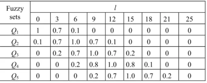
current phase and next phase. The linguistic values of l are Q1(zero), Q2(very few), Q3(few), Q4(medium), Q5(little long), Q6(long), Q7(toolong). The linguistic values of Δl are NB, NS, O, PS, PB. The membership functions for variable l and Δl are shown in Table I and Table II.
The output variable is the green increase time ΔG. The linguistic values of ΔG are G1(zero), G2(very few), G3(few), G4(medium), G5(little long), G6(long), G7(too long). The membership functions for variable ΔG are shown in Table III.
TABLE I.
MEMBERSHIP FUNCTIONS FOR VARIABLEl
Fuzzy sets l 0 3 6 9 12 15 18 21 25 Q1 1 0.7 0.1 0 0 0 0 0 0 Q2 0.1 0.7 1.0 0.7 0.1 0 0 0 0 Q3 0 0.2 0.7 1.0 0.7 0.2 0 0 0 Q4 0 0 0.2 0.8 1.0 0.8 0.1 0 0 Q5 0 0 0 0.2 0.7 1.0 0.7 0.2 0 Q6 0 0 0 0 0.1 0.7 1.0 0.7 0.2 Q7 0 0 0 0 0 0 0.2 0.8 1.0 TABLE II.
MEMBERSHIP FUNCTIONS FOR VARIABLEΔl
Fuzz y sets Δl -9 -6 -3 0 3 6 9 NB 1 0.6 0.2 0 0 0 0 NS 0.5 1 0.5 0.1 0 0 0 O 0 0 0.6 1.0 0.6 0 0 PS 0 0 0 0.1 0.5 1 0.5 PB 0 0 0 0 0.1 0.5 1
Fuzzy reasoning summarizes people’s control experience, different control may be adopted according to different measured value, for traffic control, seven rules may be acquired according to its features. Table IV shows the 33 fuzzy rules by summarizing practice and expert’s experience.
Maximum defuzzification approach is used for Fuzzy decision.
V. BP NEURAL NETWORK ALGORITHM USED TO IMPLEMENT FUZZY CONTROLLER
Although the fuzzy controller with the advantage of expert reasoning doesn’t require accurate mathematic models, the fuzzy rules and membership functions are unalterable, which can’t adapt variable traffic flow constantly.
Artificial neural network is a system which made up of many nodes called neuron, it can simulate basal features of brain, and deals with information by adopting parallel and distributed mode, its response speed of hardware
TABLE III.
MEMBERSHIP FUNCTIONS FOR VARIABLEΔG
Fuzzy sets ΔG 3 6 9 12 15 18 21 24 27 G 1 1 0.8 0.3 0 0 0 0 0 0 G 2 0.7 1 0.6 0.1 0 0 0 0 0 G 3 0.1 0.7 1 0.7 0.1 0 0 0 0 G 4 0 0 0.1 0.6 1.0 0.6 0.1 0 0 G 5 0 0 0 0 0.2 0.7 1 0.7 0.2 G 6 0 0 0 0 0 0.1 0.6 1 0.6 G 7 0 0 0 0 0 0 0.1 0.7 1 TABLE IV . FUZZY CONTROL RULES
l Δl NB NS O PS PB Q1 G 1 G 1 G 1 - - Q2 G 2 G 2 G 2 G 1 G 1 Q3 G 3 G 3 G 3 G 2 G 2 Q4 G 4 G 4 G 4 G 3 G 3 Q5 G 5 G 5 G 5 G 4 G 4 Q6 G 6 G 6 G 6 G 5 G 5 Q7 G 7 G 7 G 7 G 6 G 6
implementation is very high, meanwhile, it has the following functions: adaptive, self-learning and fault-tolerance, etc.
The fuzzy controller above can be implemented by a four-layer neural network. The fuzzy controller network is a feedforward network that encodes the decision-making in the fuzzy rule base. The activation functions of the network are different fuzzy set operations.
Q1 Q2 Q3 Q4 Q5 Q6 Q7 NB NS O PS PB Layer 1 Input layer l Δl ΔG Layer 2 Linguistics layer Layer 3 Rules layer Layer 4 Output layer
Figure 1. Structure of Fuzzy Neural Network.
The first layer is input layer. The nodes represent input linguistic variables l and Δl.
The second layer is membership-function layer. This layer computes the values of the membership functions of the input variables.
The third layer is a fuzzy rule base layer. It does the “AND-MIN” operation.
The fourth layer is an output layer. It’s a defuzzification process which calculates the total output of the rule base.
The network training process is that: Input the values of the algorithm in network and the sample values showed in table 1-4. Initialize the weights of the network to 1, the fuzzification of the condition part is performed. Train the weights of the network in term of the error gradient descent. If the trained error is less than the demanded trained error, the training can be end and the weights are outputted, else the training of the weights will continue.
VI. SIMULATION RESEARCH
In order to compare the effect of different control methods, we build the simulation plate and test the performance of three traffic control methods on the computer. The three methods are fixed timing control (FTC), fuzzy control (FC) and this paper’s transit-priority fuzzy neural network control (TP-FNNC). We program the simulation procedure with MATLAB 7.0 and VC++.
Traffic flow Vehicle detectors West South North East
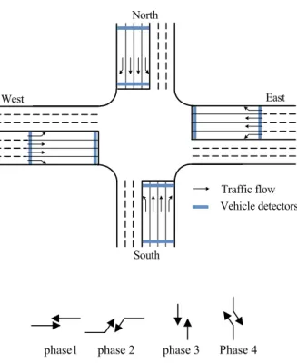
Figure 2. Structure of Intersection and Phases
The representative signal control intersection and the phases are shown graphically in Fig.2. In each lane there are two vehicle detectors used to detect the number of cars and buses. The distance between the two detectors in any lane is assumed to 150m. If the average space headway of car is 6m, and the buses’ is 12m, then the 150m lane could at most contain 25 cars or 12 buses, and all the vehicles in the lane can pass through the intersection with the mean speed of 10m/s in the period of minimum green time (assumed to 15s). Assume the maximum green time of the straight direction flow is 55s, the maximum green time of left turn flow is 30s, and the maximum stopping time which drivers can tolerate
max
T
is 120s. Supposing arrival rate of traffic flow at this intersection is from 0.0 to 0.6 vehicles per second. Special vehicle arrival rate is 1 vehicle per 5 minutes. Buses arrive randomly and its proportion varies from 0% to 30%.Assume mean passenger capacity of cars (the weight) C
w
is 3, and mean passenger capacity of busw
Bis 30. Simulation is carried out eight times, and simulation time per time is one hour. During simulation, the delays of vehicles and passengers are evaluated by following equations:∑
==
n i i vD
n
D
11
(6))
(
1
1 1∑
∑
= =+
+
=
C nB i i B n i i C B B C C pw
D
w
D
w
n
w
n
D
(7)Here Dv is the mean vehicle delays, Dp is mean
passenger delays, Di is the delay of vehicle i, nC is the
number of cars, nB is the number of buses, n=nC+nB.
In the special transit-priority simulation, we get perfect result which the special vehicle delays range is from 3.1 to 8.8 second.
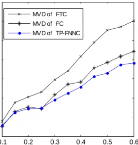
The normal transit-priority simulation results of three methods are shown in Fig.3-4. Fig.3-4 shows that Mean passenger delays (MPD) of TP-FNNC are increased by 23% than FCC at best. The delays using the last two methods have evident improvement comparing with the method of fixed timing control. This paper’s method has best performance in decreasing passenger delays than any other methods, and its mean vehicle delays is also less than others. 0.1 0.2 0.3 0.4 0.5 0.6 5 10 15 20 25 30 35 40
Vehicle arrival (vehicle per second)
M e an V e hi c le D el ay (M V D ) ( s e c on d) MVD of FTC MVD of FC MVD of TP-FNNC
Figure 3. Simulation Results of MVD
0.1 0.2 0.3 0.4 0.5 0.6 5 10 15 20 25 30 35 40
Vehicle arrival (vehicle per second)
M e an P a s s e ng e r D e la y (M P D )( s ec on d) MPD of FTC MPD of FC MPD of TP-FNNC
Figure 4. Simulation Results of MPD
VII. CONCLUSIONS
In this paper, a method called transit-priority fuzzy neural network control (TP-FNNC) is applied to the signal control of intersection. In this method, the special vehicles will be absolutely preferential. In the normal transit-priority, the phase selection is according to traffic urgency of every phase; the design of a fuzzy controller for green increase time considers the vehicle number in the current phase and next phase. A four-Layer neural network is used to implement this fuzzy controller. Simulation results show that this fuzzy neural controller plays good performance. The mean passenger delays and mean special vehicle delays are reduced obviously.
ACKNOWLEDGMENT
This work was supported by National Natural Science Foundation of China (60664001) and by the Natural Science Foundation of Jiangxi Province of China( 2010GQS0076).
REFERENCES
[1] C.P. PAPPIS, E. H.MAMDANI. “A fuzzy logic controller
for a traffic junction,” IEEE Trans on system. Man and Cybernetics, vol.7, no.10, pp. 707- 717, 1977.
[2] M.B. Trabia, M.S. Kaseko and M. Ande, “A two-stage
fuzzy logic controller for traffic signals,” Transportation Research Part C, vol.7, no.6, pp. 353-367, 1999.
[3] L. XU, L. XI, L. ZHONG, “Adaptive multi-phase fuzzy
control of single intersection based on neural network,” China Journal of Highway and Transport, vol. 18, no. 3, pp. 90-93, 2005.
[4] Y. S. Murat, E. Gedizlioglu, “A fuzzy logic multi-phased
signal control model for isolated junctions.” Transportation Research Part C: Emerging Technologies, vol. 13, no. 1, pp. 19-36, 2005.
[5] R. Li , H. Lu, “Bus-priority traffic signal multi-layer fuzzy
control model,” Qinghua Daxue Xuebao/Journal of Tsinghua University, vol. 46, no. 9, pp. 1510-1513.
[6] Schmöcker J.D., Ahuja S., Michael G.H. Bell,
“Multi-objective signal control of urban junctions - Framework
and a London case study.” Transportation Research Part C:
Emerging Technologies, 2008, v 16, n 4, p 454-470
[7] X. FAN, Y. LIU, “Alterable-Phase Fuzzy Control Based on
Neutral Network.” Journal of Transportation Systems
Engineering and Information Technology. 2008, vol. 8, no.
1, pp. 80-85.
[8] H. Gao, L. Li, R. Liu, F. Wang, “Changeable phases signal
control of an isolated intersection,” Proceedings of the IEEE International Conference on Systems, Man and Cybernetics, vol. 5, pp. 436-439, 2002.
[9] G. JIANG, H. GUO, "Traffic self-organizing signal control
method for congested isolated intersection," Journal of Harbin Institute of Technology, vol. 42, pp. 1671-1676, 2010.
[10]M. Conrad, F. Dion , S. Yagar, “Real time traffic signal
optimization with transit priority , recent advances in the signal priority procedure for optimization in real time model,” Transportation Research Record, 1634. Washington DC: Transportation Research Board, pp. 100-107, 2000.
[11]G. Chang, M. Vasudevan, C. Su, “Modelling and
evaluation of adaptive bus-preemption control with and without Automatic Vehicle Location systems,”
Transportation Research Part A: Policy and Practice. 1996, vol.30, pp. 251-268.
[12]D. Yao, Y. Su, Y. Zhang, L. Li, S. Cheng, Z. Wei, “Control
strategies for transit priority based on queue modeling and surrogate testing,” Journal of Intelligent Transportation Systems: Technology, Planning, and Operations, vol. 13, no. 3, pp. 142-148, 2009
[13]J. Stevanovic, A. Stevanovic, P. Martin, T. Bauer,
“Stochastic optimization of traffic control and transit priority settings in VISSIM,” Transportation Research Part
C: Emerging Technologies, vol. 16, no. 3, pp. 332-349,
2008.
[14] Z. Zou, "An Arterial Bus Signal Priority Algorithm,"
Journal of Tongji University(Natural Science), vol. 36, pp. 1368-1371, 2010.
Xianyan Kuang is born in Jiangxi Province, China, in 1976. He is currently a Ph.D. candidate at South China University of Technology, GuangZhou, China. He received his MS degree in control theory and control engineering from Jiangxi university of Science and Technology, China, in 2005 and BS degree in computer application from Wuhan university, China, in 1999. He is an associate professor at Jiangxi university of Science and Technology, GanZhou, China. His major interests include ITS, traffic control and simulation, and optimal control.
Lunhui Xu is an professor(doctoral supervisor) in School of Civil Engineering and Transportation, South China University of Technology, GuangZhou, 341000, China. His research interests include intelligent control, optimal control, traffic engineering and ITS.