Data Resource Management in Throughput Processors
byJohn S. Kloosterman
A dissertation submitted in partial fulfillment of the requirements for the degree of
Doctor of Philosophy
(Computer Science and Engineering) in the University of Michigan
2018
Doctoral Committee:
Professor Scott Mahlke, chair Professor Trevor Mudge Professor Kevin Pipe
John S. Kloosterman [email protected] ORCID iD: 0000-0001-8180-1237
ACKNOWLEDGMENTS
Completing this dissertation would not have been possible without the support of many people. I would like to thank Scott Mahlke for making this research possible as my advisor; his insight made an impact on every part of this dissertation. Alongside his research mentorship, he has also helped me learn the other skills that make research successful – presenting my work in a way that is understandable and convincing, as well as managing the different stakeholders in the work. I also had the privilege of working with Trevor Mudge throughout my time at Michigan. Lingjia Tang and Kevin Pipe have provided valuable insights as committee members that improved this work.
I am proud to have been a part of the CCCP research group. As I started graduate school, Ankit Sethia showed me how to be an effective graduate student during our meetings together with Scott. Mehrzad Samadi, Hyoun Kyu Cho, Janghaeng Lee, Daya Khudia, Gaurav Chadha, Jason Park, Shruti Padmanabha, and Andrew Lukefahr were a welcoming group of people who I had the privilege of joining and working alongside. I enjoyed collaborating with Anoushe Jamshidi on our GPU research; many of the ideas in Chapter4came out of our conversations. Jiecao Yu, Babak Zamirai, Jon Bailey, Shikai Li, Sunghyun Park, Salar Latifi, Hossein Golestani, Ze Zhang, and Pedram Zamirai have been a great group to work alongside these past years. Jonathan Beaumont was also a pleasure to work with on the power models used in this dissertation.
I am grateful to my mentors through the different stages of my career so far. Joel Adams gave me my first experience doing research with GPUs as an undergraduate, helped me through the graduate school admissions process, and has continued being there throughout my Ph.D. As I prepare for life after graduate school, Drew DeOrio has helped me through the job search process and given me the nudges I needed to finish writing.
to use DOS at four years old, to using the farm truck to pick up loads of free computer parts, to giving me all that space in the basement to tinker, they have always been encouraging and supportive. They have been patient through all the times I have had to stay in the States to work on research.
Finally, I could not have made it through graduate school without the support of my wife Liz. She has been there through all the exams, paper deadlines, conferences, and job interviews that would otherwise have been too much for me. She’ll be glad I can finally get some rest.
TABLE OF CONTENTS
Acknowledgments . . . ii
List of Figures . . . vii
List of Tables . . . xi
Abstract. . . xii
Chapter 1 Introduction . . . 1
1.1 Data Management Inefficiencies . . . 4
1.1.1 Memory Divergence and Cache Thrashing . . . 5
1.1.2 Register File Energy Overhead . . . 5
1.1.3 Inter-Application Contention. . . 6
1.2 Contributions . . . 6
1.2.1 Increasing Memory Throughput . . . 6
1.2.2 Reducing Register File Energy and Storage . . . 7
1.2.3 Controlling Interference in Shared GPUs . . . 7
2 Background . . . 9
2.1 SM Design . . . 9
2.2 Memory System Design. . . 10
2.3 Programming Model . . . 11
2.4 Design Convergence in Desktop, Data Center, and Mobile. . . 12
3 Inter-Warp Memory Request Merging and Prioritization . . . 13
3.1 Introduction . . . 13
3.2 Background and Motivation. . . 15
3.2.1 Background. . . 15
3.2.2 Oversubscription of L1 Bandwidth . . . 18
3.2.3 Increasing Coalescing Window Size . . . 20
3.3 WarpPool Design . . . 21
3.3.1 Overview . . . 21
3.3.2 Instruction Queues . . . 23
3.3.3 Intra-Warp Coalescers . . . 24
3.3.5 Request Selector . . . 25
3.3.6 Metadata Tracker . . . 26
3.3.7 Writeback. . . 28
3.3.8 Stores and Memory Consistency . . . 28
3.3.9 Resource Configuration . . . 29 3.3.10 Verilog Implementation . . . 30 3.4 Evaluation . . . 32 3.4.1 Methodology . . . 32 3.4.2 Results . . . 33 3.4.3 Case Study . . . 36 3.5 Related Work . . . 37 3.6 Conclusion . . . 38
4 Register File Storage and Energy Reduction . . . 40
4.1 Introduction . . . 40
4.2 RF Replacement Challenges . . . 43
4.2.1 Capacity Allocation . . . 43
4.2.2 Memory Side Bandwidth. . . 45
4.2.3 L1 Cache Capacity . . . 46
4.3 Design Overview . . . 46
4.4 Compiler Code Generation . . . 48
4.4.1 Region Creation . . . 48
4.4.2 Region Creation Algorithm . . . 50
4.4.3 Register Lifetime . . . 50
4.4.4 Control Flow and Register Liveness . . . 52
4.5 Hardware Design . . . 53
4.5.1 Capacity Managers (CMs) . . . 55
4.5.2 Operand Staging Units (OSUs) . . . 55
4.5.3 Compressor . . . 58
4.5.4 Metadata Encoding . . . 59
4.6 Evaluation . . . 60
4.6.1 Methodology . . . 60
4.6.2 Area and Power. . . 61
4.6.3 Energy Savings . . . 62
4.6.4 Performance . . . 64
4.6.5 Register Preload Location, L1 Bandwidth . . . 65
4.6.6 Region Sizes . . . 66
4.7 Related Work . . . 68
4.8 Conclusion . . . 70
5 Multi-Kernel Resource Management . . . 74
5.1 Introduction . . . 74
5.2 Background and Motivation. . . 77
5.2.1 GPU Architecture and Multitasking . . . 77
5.2.3 Interference under SMK . . . 79
5.2.4 Opportunities to Control Interference . . . 81
5.3 Overview . . . 82
5.3.1 Online Performance Prediction. . . 83
5.3.2 Dynamic Resource Allocation . . . 83
5.3.3 Hardware Components . . . 84
5.4 Online Performance Prediction . . . 85
5.4.1 Determining Profile Length . . . 86
5.4.2 Detecting Phase Boundaries . . . 87
5.5 Performance Controllers . . . 89
5.5.1 Controlling Warps and Memory Requests . . . 90
5.5.2 Controlling Thread Blocks and Preemption . . . 92
5.5.3 Avoiding Throughput Loss . . . 94
5.6 Evaluation . . . 95
5.6.1 Methodology . . . 95
5.6.2 Hardware Implementation . . . 96
5.6.3 Performance Targets and Throughputs . . . 97
5.6.4 Performance Predictor Accuracy . . . 99
5.6.5 Performance Targets Achieved . . . 100
5.6.6 Cloud Operator Revenue . . . 101
5.7 Related Work . . . 102
5.8 Conclusion . . . 104
6 Conclusion and Future Work. . . 105
6.1 Summary . . . 105
6.2 Future Work . . . 107
LIST OF FIGURES
1.1 Percentage of cycles any instruction was issued for a set of workloads from Parboil, Rodinia, and the NVIDIA SDK. . . 2
1.2 Percentage of cycles the load/store unit was stalled, which indicates when throughput is limited by the global memory system. . . 2
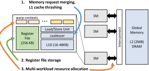
1.3 Major GPU components involved in data movement and storage. This thesis focuses on three critical data management components: global memory merging and caching in shader cores, register storage, and allocation of resources between multiple co-running workloads. . . 4
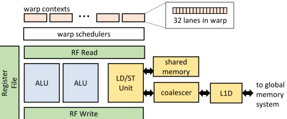
2.1 Design of a GPU core, called a streaming multiprocessor (SM). GPUs are optimized for throughput rather than individual thread latency and execute 32-wide vector in-structions. . . 10
2.2 GPU system design, where SMs and memory partitions are on opposite sides of an interconnect. The GPU communicates with a host system through PCI Express data transfers to and from DRAM. . . 11
3.1 Diagram of GTX 480 memory system. Each SM has a load/store unit with a memory coalescer which sends requests to a private L1 cache. Requests to shared L2 caches and DRAM partitions are sent over an interconnect.. . . 16
3.2 Memory request reduction for thespmvbenchmark, showing the number of requests remaining at each level of the memory hierarchy as the coalescer and caches convert locality into fewer requests. . . 16
3.3 Memory throughput-limited workloads overwhelm the coalescing system either though generating many requests with memory divergence or by causing cache re-source shortages by saturating memory bandwidth. The kernel number is its sequence in the kernel execution order in the benchmark. . . 17
3.4 A portion of the execution of theGEMMbenchmark. The solid line is the number of memory instructions waiting to be scheduled. The background is grey when the L1 cache resources are full. The bars at the bottom show when arithmetic is scheduled. For the cache resource-bound benchmarks, there is little overlap of computation with cache resource stalls. . . 17
3.5 Many memory throughput-limited kernels show a large degree of inter-warp spatial locality. Each cell corresponds to a kernel, and inside each cell the window size gets larger from left (baseline window of only intra-warp coalescing) to right (window of 128 requests after intra-warp coalescing). As the window size increases the number of requests that must be sent to the cache decreases.. . . 19
3.6 Diagram of theWarpPoolsystem. . . 22
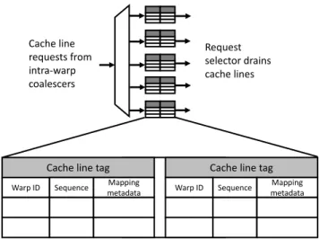
3.7 A diagram of the inter-warp coalescing queues. Requests exiting the intra-warp coa-lescers are merged with other requests to the same cache line in these queues. . . 25
3.8 Common mapping patterns from cache line words to threads . . . 27
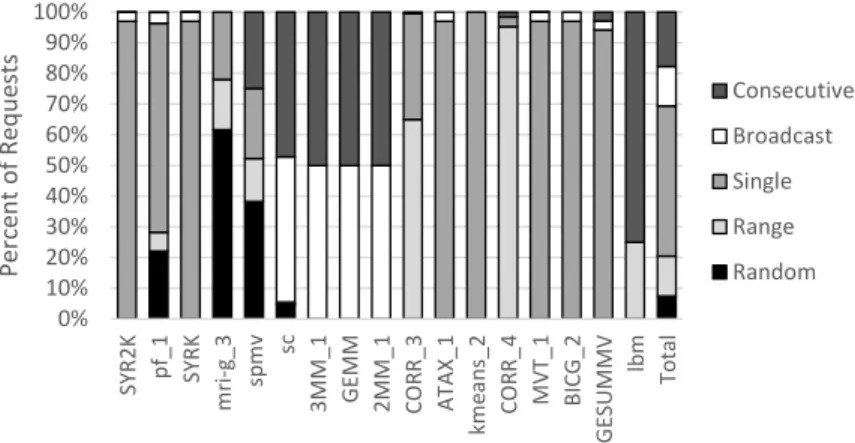
3.9 Relative occurrence of mapping patterns in benchmarks . . . 28
3.10 Per-SM area breakdown ofWarpPoolcomponents, with a total area of 0.36mm2per
SM. (* = SRAM area calculated using CACTI) . . . 31
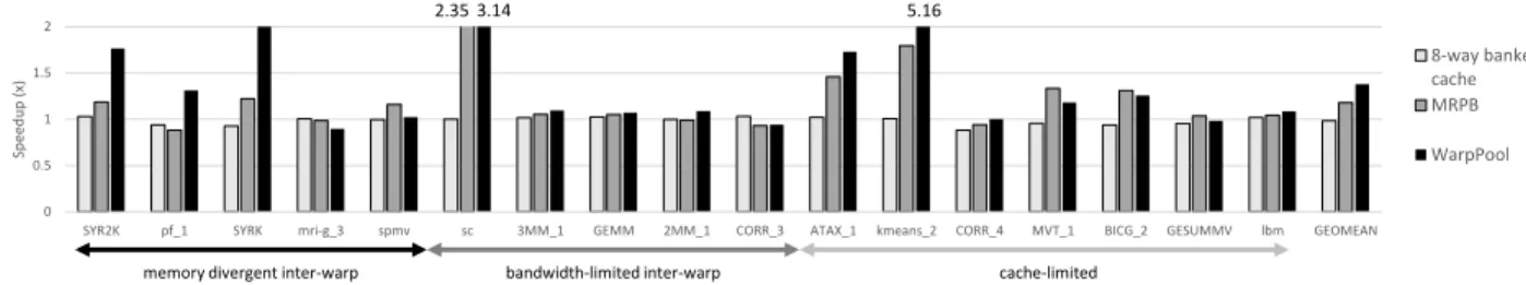
3.11 Speedup of GPU with banked cache, MRPB, andWarpPoolover GTX 480 baseline. . 33
3.12 Average number of requestsWarpPoolcoalesced into an L1 cache request, compared against the number of requests an 8-bank cache serviced each cycle. . . 34
3.13 Number of misses per thousand instructions (MPKI) for MRPB and WarpPool, nor-malized to the baseline. . . 35
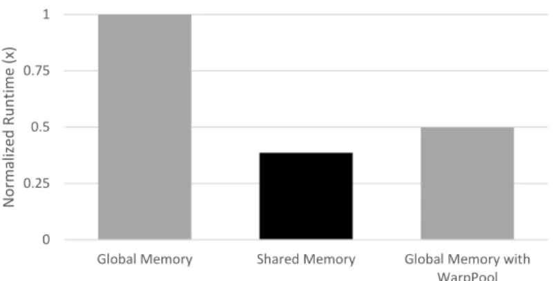
3.14 Relative execution time of matrix transpose versions, normalized to na¨ıve global mem-ory version. . . 36
4.1 Comparison of GPU register energy reduction techniques that change how execution units (EUs) read operands from the register file (RF) . . . 41
4.2 Average register working set in 100 cycle window for GTO and 2-level warp sched-ulers in baseline 2048 KB register file for benchmarks in Rodinia [17] . . . 43
4.3 Accesses to the register backing store per 100 cycles during the steady state of hotspot for baseline, RF hierarchy [32] with 8-entry scratchpad, and RegLess with 8 entries per warp . . . 45
4.4 Walkthrough . . . 47
4.5 Count of live registers for a portion of particle filter, with low live register points highlighted . . . 49
4.6 Compiler annotations added on regions and instructions . . . 51
4.7 Determining whether a definition is soft. A soft definition of a register might not kill every thread’s values. . . 53
4.8 Block diagram of RegLess components in each SM . . . 53
4.9 Capacity manager (CM) design. CMs track which warps have registers allocated in the OSU and are ready to execute instructions. . . 56
4.10 Operand staging unit (OSU) design. OSUs store register values and service register read and writes. . . 56
4.11 Area for RegLess configurations, normalized to 2048-entry baseline RF . . . 61
4.12 Combined static and average dynamic power for RegLess configurations, normalized to baseline RF . . . 61
4.13 Run time vs. GPU energy for RegLess configurations, normalized to baseline. The line marks the Pareto frontier. . . 62
4.15 Normalized total GPU energy, including added instruction and memory accesses. The “No RF” entry is the upper bound for energy savings, which uses the baseline perfor-mance and a register file that consumes no energy. . . 63
4.16 Run time (lower is better) for 512-register RegLess design normalized to baseline with full RF. The geomean is compared with RegLess with no compressor, RFV, and RFH. 64
4.17 Location from which registers were preloaded. 0.9% of registers were preloaded from L1 and 0.013% were preloaded from L2 or DRAM.. . . 65
4.18 Average RegLess L1 requests per cycle . . . 66
4.19 Average number of preloads, average number of concurrent live registers, and standard deviation of number of concurrent live registers per region . . . 66
5.1 Diagram of GPU and SM design. In SMK [141, 146], the warp contexts are split between applications. . . 77
5.2 Resource demands for GPU workloads (methodology in Section 5.6.1); workloads on the left saturate compute resources, and workloads on the right saturate mem-ory resources. Sharing an SM between complementary workloads increases overall throughput. . . 78
5.3 Running multiple kernels using SMK results in interference. The SG benchmark is run alongside three other benchmarks, sharing resources evenly. Interference causes throughput loss for one or both workloads. . . 80
5.4 Timeline of % cycles arithmetic issued and load/store unit stalled, averaged over 100-cycle windows, for a 20,000-100-cycle interval of BP. A co-running workload is able to issue compute and memory instructions at times of low utilization. . . 80
5.5 Overview of the Scavenger system . . . 82
5.6 The Scavenger components in each SM, which use performance counters to deter-mine resource allocations. The upper components (in orange) predict the primary workload’s performance and detect when it has entered a new phase. The lower com-ponents (in blue) adjust the resource allocation to achieve the primary workload target and maximize secondary workload throughput. . . 84
5.7 Performance of excerpt of HS over time along with the difference between the mean training and validation interval IPCs. To detect an appropriate profile length, Scav-enger continues profiling until the difference stays below a threshold. . . 86
5.8 Feedback control system for active warps and outstanding memory requests. The short-term and long-term difference between the predicted IPC and actual IPC is used to adjust resource allocations using PID controllers.. . . 90
5.9 The thread block controller preempts blocks to balance warp slack between the work-loads. (a) Scavenger detects too little slack for primary workload, too much for sec-ondary. (b) Blocks of secondary workload are preempted to make way for primary. (c) Slack is more evenly distributed between workloads. . . 93
5.10 Secondary workload throughput with Scavenger compared to temporal partitioning, by primary x secondary workload category. Pairs violating the primary kernel perfor-mance target are excluded. . . 97
5.11 Geomean primary workload throughput by pair category and target . . . 97
5.12 Total primary and secondary throughput with Scavenger compared to temporal parti-tioning. Pairs violating the primary kernel performance target are excluded. . . 98
5.13 Cumulative % error and % time profiling, averaged across benchmarks vs. maximum difference between training and validation interval IPC while profiling . . . 99
5.14 Percentage of pairs where the primary kernel’s performance was below the target with 1% error margin, and the average percentage by which pairs that did not achieve the target were below the target performance . . . 100
5.15 Additional revenue per dollar realizable with Scavenger over leasing GPUs as a unit or using temporal partitioning. . . 101
LIST OF TABLES
3.1 Per-SM storage and power overhead ofWarpPoolcomponents . . . 30
3.2 Resource configuration evaluated . . . 31
4.1 GPGPU-sim simulation parameters . . . 60
4.2 Average number of static instructions per region and average dynamic cycles per region 67 5.1 Performance predictor parameters . . . 89
5.2 Controller parameters. . . 94
5.3 Simulator configuration . . . 94
ABSTRACT
Graphics Processing Units (GPUs) are becoming common in data centers for tasks like neural net-work training and image processing due to their high performance and efficiency. GPUs maintain high throughput by running thousands of threads simultaneously, issuing instructions from ready threads to hide latency in others that are stalled. While this is effective for keeping the arithmetic units busy, the challenge in GPU design is moving the data for computation at the same high rate. Any inefficiency in data movement and storage will compromise the throughput and energy efficiency of the system.
Since energy consumption and cooling make up a large part of the cost of provisioning and running and a data center, making GPUs more suitable for this environment requires removing the bottlenecks and overheads that limit their efficiency. The performance of GPU workloads is often limited by the throughput of the memory resources inside each GPU core, and though many of the power-hungry structures in CPUs are not found in GPU designs, there is overhead for storing each thread’s state. When sharing a GPU between workloads, contention for resources also causes interference and slowdown.
This thesis develops techniques to manage and streamline the data movement and storage re-sources in GPUs in each of these places. The first part of this thesis resolves data movement restrictions inside each GPU core. The GPU memory system is optimized for sequential accesses, but many workloads load data in irregular or transposed patterns that cause a throughput bottle-neck even when all loads are cache hits. This work identifies and leverages opportunities to merge requests across threads before sending them to the cache. While requests are waiting for merges, they can be reordered to achieve a higher cache hit rate. These methods yielded a 38% speedup for memory throughput limited workloads.
Another opportunity for optimization is found in the register file. Since it must store the regis-ters for thousands of active threads, it is the largest on-chip data storage structure on a GPU. The second work in this thesis replaces the register file with a smaller, more energy-efficient register buffer. Compiler directives allow the GPU to know ahead of time which registers will be accessed, allowing the hardware to store only the registers that will be imminently accessed in the buffer, with the rest moved to main memory. This technique reduced total GPU energy by 11%.
Finally, in a data center, many different applications will be launching GPU jobs, and just as multiple processes can share the same CPU to increase its utilization, running multiple workloads on the same GPU can increase its overall throughput. However, co-runners interfere with each other in unpredictable ways, especially when sharing memory resources. The final part of this thesis controls this interference, allowing a GPU to be shared between two tiers of workloads: one tier with a high performance target and another suitable for batch jobs without deadlines. At a 90% performance target, this technique increased GPU throughput by 9.3%.
GPUs’ high efficiency and performance makes them a valuable accelerator in the data center. The contributions in this thesis further increase their efficiency by removing data movement and storage overheads and unlock additional performance by enabling resources to be shared between workloads while controlling interference.
CHAPTER 1
Introduction
Graphics Processing Units (GPUs), although originally designed for accelerating 3D graphics in desktop computers, have proven effective at other tasks that require high computational throughput such as simulations, artificial intelligence, and image processing. Because of this, general purpose GPUs are found not just in desktop PCs but in mobile devices and servers as well. GPUs are optimized for throughput, using a highly multithreaded architecture that switches between threads to hide stalls; this design allows them to be more efficient than CPUs at many tasks. For com-parison, one current GPU, NVIDIA’s Tesla P100, can achieve 10 single-precision teraflops at 33 gigaflops/watt [44], compared to a large 24-core CPU, Intel’s Xeon E7-8870, that achieves 96 gigaflops at 7 gigaflops/watt [48].
In data centers, GPUs are used to complete tasks that need more performance than CPUs can offer. GPUs are used in Google and Facebook data centers for artificial intelligence applications, such as training neural networks [25,72]. Databases accelerated by GPUs enable interactive anal-ysis of very large data sets [91,10]. GPUs are not only useful for large companies – public cloud providers are responding to demand by offering virtual machines connected to GPUs. Amazon offers instances with GPUs [11], and Google’s public cloud uses a PCIe switch system to connect GPUs to any of its virtual machines [42].
The design constraints for a data center GPU differ from those for a desktop graphics card. Energy efficiency is more important, as a large fraction of data center costs come from power consumption and cooling [12]. To help achieve this, recent data center GPUs include accelerators
0% 20% 40% 60% 80% 100% % cy cl e s ins tru cti on s is su e d
Figure 1.1: Percentage of cycles any instruction was issued for a set of workloads from Parboil, Rodinia, and the NVIDIA SDK.
0% 20% 40% 60% 80% 100% % cy cl e s load /s to re u n it sta ll e d
Figure 1.2: Percentage of cycles the load/store unit was stalled, which indicates when throughput is limited by the global memory system.
for matrix operations and support for lower-precision floating-point calculations [101]. Also, in a data center, multiple applications or users are scheduled on the same physical hardware to increase utilization. Data center GPUs now include ways to share the same hardware between multiple tasks and users: current hardware can expose multiple virtual devices per physical GPU that share hardware with temporal partitioning [45], and other work has examined how to add memory virtu-alization and protection to GPUs [15].
GPUs in mobile devices must be designed with similar constraints in mind. Energy efficiency is visible to mobile users, as it determines battery life. Performance is also vital – mobile GPUs have the opportunity to enable new types of applications that require heavy computation, but in order for developers to justify the additional programming effort, the performance and efficiency difference must be compelling. Sharing hardware between tasks is also important on mobile GPUs, as users
expect smooth graphics even while other types of computation, such as neural network inference, are being run on the GPU [6].
Better reaching these goals of improved energy efficiency and support for sharing hardware between multiple tasks requires focusing on data movement and storage. GPUs achieve their per-formance by having many arithmetic units, but to keep them utilized, they must be supported by a memory and register system that has equally high performance. Any data bottleneck in the sys-tem leads to underutilization of computation resources, stalls, and lower efficiency. Adding more arithmetic resources will only show performance gains if data movement capacity scales in step. However, even current designs have difficulty keeping up with memory throughput demands. Fig-ure1.1shows the percentage of cycles that any instructions were issued on a set of GPU workloads, which is often below 50%. The major bottleneck often is the global memory system, as Figure1.2
demonstrates by showing the load/store unit, responsible for interfacing with the global memory system, is often stalled.
Alongside this performance bottleneck, there are also energy overheads in the GPU due to data storage. Part of what makes GPUs efficient are strategies, such as grouping instructions into SIMD vectors, that reduce the overheads required in more general-purpose processors like CPUs. Although these strategies work for reducing computation overhead, the GPU execution model that interleaves threads does not allow for similar straightforward ways to reduce data storage overhead in the register file and scratchpad memories, since the data to be computed on must always stay accessible should the instructions using it be scheduled.
This thesis manages data movement and storage resources in a way that improves energy effi-ciency and makes GPUs more amenable to a shared data center environment. Intelligent manage-ment of data resources is possible because GPUs have options between which work to schedule and flexibility in which order to schedule it. Because GPUs run many threads at once, there are options between which which threads to run, allowing the GPU to make priority decisions between threads and workloads at a very fine granularity. There are also few ordering constraints between threads, which gives the freedom to reorder and merge memory requests and start and stop portions
warp contexts
...
Register File (256 KB) L1D (16-48KB) Load/Store Unit coalescer SM SM SM In te rco n n e ct Global Memory L2 (2MB) DRAM1. Memory request merging, L1 cache thrashing
2. Register file storage
3. Multi-workload resource allocation
Figure 1.3: Major GPU components involved in data movement and storage. This thesis focuses on three critical data management components: global memory merging and caching in shader cores, register storage, and allocation of resources between multiple co-running workloads. of workloads to adjust resources. This thesis uses these opportunities to unlock additional energy efficiency and performance for data center and mobile GPUs.
1.1
Data Management Inefficiencies
There are three places where the management of data resources on a GPU is especially critical, shown in Figure 1.3. The first is inside each of the 16 GPU shader cores, which have their own load-store units and L1 cache. Even when running a single workload, the load-store units and L1 cache often do not have sufficient throughput due to memory divergence and cache thrashing. The second is also inside the core, at the register file, which is very large as it is provisioned to hold every register with similar access times. The third is the allocation of thread contexts in the cores between workloads and the number of memory requests each workload can send to the global memory system. This section will look at each of these places in turn.
1.1.1
Memory Divergence and Cache Thrashing
One data management inefficiency comes from the GPU processing cores being unable to issue enough requests to the memory system. GPUs use SIMD vector instructions, including loads and stores, that execute 32 lanes in parallel. This enables each lane in a vector load or store to reference a different address. Often, the addresses in each lane will be consecutive words in the same cache line, in which case loading that single cache line will be enough to complete the vector load. However, when the lanes reference multiple cache lines, calledmemory divergence, multiple requests must be sent to the memory system to satisfy the one load instruction. In the worst case, one load requires 32 requests, creating a throughput bottleneck.
A related inefficiency comes from cache thrashing. Because GPU cores run many threads simultaneously but have a small (32KB) L1 data cache, each thread can only store on the order of bytes in the cache before evicting another thread’s data. While techniques to reduce thrashing to improve performance are well-studied in previous work [117, 123, 51], thrashing also blocks requests from leaving the core for the rest of the memory system by filling up MSHRs and using scarce bandwidth to the L2 and DRAM. Therefore, inefficient use of the data cache not only causes increased latency but also lower memory throughput.
1.1.2
Register File Energy Overhead
The register file is the largest data storage structure in a GPU and a source of energy overhead. GPUs’ multithreaded architecture means that the register file needs to store the registers for every thread. Because so many threads are active on each core, the register file is very large — 256KB per core in recent designs. It also must support many accesses per cycle, as one vector instruction may have three 128-byte input registers and produce a 128-byte output. This makes the register file expensive to access, consuming up to 15% of total GPU power [77]. Since the register file only provides value to the GPU as a support for computation, this power represents an overhead in the GPU design that should be minimized.
1.1.3
Inter-Application Contention
GPU kernels consist of many threads, but each thread is identical to the others. This means the resource demands for each thread are very similar, and a kernel while executing will tend to saturate one resource and underutilize others. Running multiple workloads simultaneously on the same GPU allows the workloads to saturate different resources, leading to a throughput boost. However, during times when the workloads require the same resources, they interfere with each other. This interference leads to some workloads choking others’ performance and other unpredictable effects. In a data center or public cloud environment, controlling this interference will be necessary to harness the throughput boost of sharing the GPU while providing performance targets that are useful to customers.
1.2
Contributions
This thesis addresses these inefficiencies through intelligent management of data resources. Chap-ter 3 describes a memory merging and prioritization system that increases memory throughput inside a GPU core. Chapter 4 details a register file replacement that requires much less storage and access energy while not impacting performance. Chapter5develops a system for controlling the interference between kernels co-running on the same GPU, creating two tiers of service. To-gether, these pieces attack the sources of energy inefficiency and low utilization in the GPU data movement and storage systems.
1.2.1
Increasing Memory Throughput
Existing GPUs have a memory coalescer which merges requests to the same cache line in a vector load instruction, as often each lane in a vector load accesses a different word in the same cache line. This type of spatial locality, where nearby threads access nearby data, is also present between lanes in different warps, but ignored by current hardware. By exploiting this locality, requests can be merged across warps before those requests are sent to the cache. This helps mitigate throughput
loss due to memory divergence because effectively more than one request per cycle is being sent to the cache. The same hardware used for merging requests can also be used to reorder requests to put loads from the same warps closer together in time, increasing memory throughput by increasing the L1 hit rate. Chapter3introduces theWarpPoolsystem that finds these new merging opportunities and queues memory requests to issue them in a more cache-friendly order, resulting in a 38% speedup via an 8% increase in merges and a 23% reduction in L1 cache misses.
1.2.2
Reducing Register File Energy and Storage
Instead of having enough storage for every register, this thesis replaces the register file with a staging unit which stores only the registers that will be imminently used by a small set of active warps. Most registers have a short lifetime and only need a temporary allocation in the staging unit. The few long-lived registers can be evicted from the staging unit to the L1 cache when they will not be accessed. Compiler annotations enable this system, as they allow register usage information gathered with static analysis to be visible by the hardware at run time to make allocations in the staging buffer and transfer values in just as registers are about to be accessed. In Chapter 4, the RegLesssystem implements this compiler-guided register buffer, reducing register storage to 25% of its original size with no average-case performance loss.
1.2.3
Controlling Interference in Shared GPUs
Public cloud operators like Amazon’s AWS and Google’s GCP have multiple tiers of service in order to increase utilization. For example, spot instances are sold to customers at a discount to fill unused capacity, with the condition that they may be preempted at any time when that capac-ity is needed. In Chapter 5, theScavenger system controls the interference caused by sharing a GPU between multiple workloads to create similar tiers: one tier with a high performance tar-get for customers requiring maximum throughput, and a second lower-performance tier for batch jobs. Because sharing the GPU will create a throughput surplus, the cloud operator can either operate less physical hardware or capture the excess throughput as profit. Scavenger increases the
batch workload throughput by 1.35x compared to temporal partitioning while maintaining a 90% performance target for the high-performance tier, increasing overall GPU throughput by 9.3%.
CHAPTER 2
Background
This thesis optimizes data movement and storage on graphics processing units (GPUs), throughput processors that operate on thousands of threads in parallel. Because each GPU thread is indepen-dent, instructions can be issued from any available thread, with the goal of keeping the functional units utilized. GPU kernels are complete when every thread finishes, so maintaining maximum utilization and throughput will finish the kernel in the minimum time possible. GPUs are opti-mized for running workloads consisting of many identical threads, setting them apart from other throughput-oriented processors like Niagara [68], because their original design was optimized for graphics vertex and fragment shaders, where the same code executes on every vertex or pixel. This chapter describes the baseline GPU architecture that the subsequent techniques in this thesis build upon.
2.1
SM Design
Figure 2.1 shows the design of a GPU core, or streaming multiprocessor (SM). Each hardware thread, called awarp, is allocated awarp context. As one of the optimizations for running many identical threads, warps issue 32-wide SIMD instructions. The warp contexts track the current PC for each warp and can activate and deactivate individual threads in a warp to implement condi-tional branches. Thewarp scheduler sends instructions to the functional units, selecting between ready warps; it is divided into several independent schedulers to allow more than one warp to be issued per cycle. The register file on a GPU is very large, in the hundreds of kilobytes per
32 lanes in warp warp contexts warp schedulers R e g is te r F il e shared memory RF Read ALU LD/ST Unit coalescer ALU RF Write to global memory system
...
L1DFigure 2.1: Design of a GPU core, called a streaming multiprocessor (SM). GPUs are optimized for throughput rather than individual thread latency and execute 32-wide vector instructions. SM, because each thread in each warp is allocated its own register context. The functional units include floating-point ALUs and a load/store unit. The load/store unit handles requests to the dif-ferent GPU memory spaces, including theshared memoryscratchpad andglobal memory, which is backed by data caches and DRAM. Global memory requests are sent through acoalescer, which merges memory requests made by different threads in the same warp, and then are sent to an L1 data cache. The effectiveness of the L1 cache depends heavily on the workload, so some GPU de-signs disable it by default. In this thesis, Chapter3is built on a GPU where the L1 cache is enabled by default, and Chapters4and5model one where the L1 does not cache requests by default.
2.2
Memory System Design
The overall GPU system design, encompassing the SMs and the global memory system, is shown in Figure 2.2. The SMs lie on one side of the interconnect with shards of L2 cache and DRAM on the other. Neither the SMs or the L2 shards communicate with other units on their side of the interconnect, as the tasks on one SM are independent of those on another, and the L2 shards are partitioned by address. Each L2 shard includes a memory controller which communicates with one of the two channels exposed by each GDDR DRAM chip. There is significant latency communicating to L2, as graphics ROPs sit in front of the L2, so even L2 hits have high latency.
...
SM SM SM SM In te rco n n e ct L2 DRAM L2 L2 DRAM L2...
PCI Express connection to hostFigure 2.2: GPU system design, where SMs and memory partitions are on opposite sides of an interconnect. The GPU communicates with a host system through PCI Express data transfers to and from DRAM.
This is not an issue in the GPU design because independent instructions from other threads can hide the latency in any individual thread. Sustaining high bandwidth is more important – the L2 cache is more important for reducing duplicate requests than latency.
Data is transferred to and from the GPU though a PCI Express bus. There is a very large bandwidth differential between DRAM and PCI Express, with the DRAM able to supply 224 GB/s in the GPU models modelled in this thesis, whereas PCI Express 3.0 x16 has a limit of 16 GB/s. In this thesis, the experiments assume that the data is already present in DRAM. Complementary work [39, 19,20] has examined how to overlap computation with memory transfers to reduce the overall task turnaround time.
2.3
Programming Model
General purpose GPU applications are typically implemented in languages like CUDA [100] and OpenCL [127], which are extensions to C++. In the programming model these use, programmers write code from the perspective of one thread. Although each thread must largely be independent, the programming model groups threads intoblocks. The threads in a block are allocated the same region of scratchpad shared memory and can synchronize using barriers. In hardware, this requires that the warps in a block must run on the same SM and have their resources allocated as a group.
2.4
Design Convergence in Desktop, Data Center, and Mobile
There is increased convergence in GPU designs found in desktop PCs, servers, and mobile devices. For example, NVIDIA’s Pascal architecture was used in GeForce gaming GPUs, Tesla compute accelerators, and integrated in a mobile SoC used in the Jetson TX1 board. The same design is scalable to these different environments by varying the number of SMs – the GTX 1080 has 20, the Tesla P100 has 60, and the Jetson TX1 has 2. This convergence means that techniques optimizing the GPU hardware in one setting can be applicable to the others, and that the same programming model and kernels can be used in each of these different settings. In this thesis, desktop GPU models like the GTX 480 and 980 are used for simulation, but because the techniques respect the loose coupling between SMs, the techniques can be extended to server GPUs with larger number of SMs and mobile GPUs with fewer without scalability issues.CHAPTER 3
Inter-Warp Memory Request Merging and
Prioritization
3.1
Introduction
GPUs are throughput processors designed to hide memory latency using multithreading. During the time some threads on the GPU are waiting for long-latency memory operations, others can be scheduled to do computation. However, in order for this strategy to keep the utilization of the arithmetic units high, data needs to come from the memory system fast enough to maintain a set of threads that are ready to do computation. Therefore, keeping the arithmetic units utilized depends on the throughput of the memory system matching the throughput of the compute pipelines.
However, previous studies have shown that for many benchmarks, the throughput of the global memory system is not adequate to keep the GPU from stalling. This can be due to saturated DRAM bandwidth [124], limited L1 cache resources such as MSHRs and cache sets [51], or small per-thread cache capacity [118]. To achieve high throughput despite bandwidth limitations in the global memory system, the GPU has a memory hierarchy that merges requests to the same cache lines to reduce traffic.
On a GPU, threads in a 32-wide warp execute in lockstep, but the threads in one load can generate accesses to many different cache lines. Amemory coalesceris the first unit in the memory hierarchy, responsible for combining memory accesses to the same cache line made by the 32 threads in a warp. This unit is effective because spatial locality is expressed in a GPU through
nearby threads accessing the same cache lines [46]. Combining requests early in the memory pipeline is better for performance and energy efficiency than sending duplicate requests to the higher-level caches and DRAM.
However, the coalescer can become the bottleneck in memory system throughput, which hap-pens under memory divergence, where the threads in a warp request more than one cache line in a load or store instruction. Because the L1 can only service one request per cycle, up to 32 requests must be serialized over 32 cycles instead of being serviced simultaneously. Another throughput problem is caused by limited cache resources, where the memory system stalls when the cache cannot allocate a resource like an MSHR to issue another outstanding miss. In both of these cases, the GPU becomes underutilized because the memory system cannot supply data fast enough to keep the arithmetic units busy.
The current memory coalescer is limited to merging requests between threads in the same warp. However, we show that spatial locality is not limited to threads in the same warp, so allowing the coalescer to merge requests from threads in multiple warps would allow for for a greater reduction in requests. If the coalescer were able to merge requests across warps using this inter-warp spatial locality before they reach the L1 cache, it would increase the effective bandwidth of the cache by relieving the one access per cycle bottleneck. During times when L1 resources are at a premium, it would enable resources to service requests from as many warps as possible. As well, having requests from multiple warps in scope allows the coalescer to act as a gatekeeper to the L1 cache and reduce thrashing.
We propose a novel memory coalescer, WarpPool, which is able to find inter-warp spatial lo-cality. It increases the effective throughput to the L1, uses cache resources more efficiently, and reduces cache thrashing by prioritizing some warps’ access to the cache. After a first level of co-alescing to find intra-warp spatial locality, requests are inserted into inter-warp coco-alescing queues that merge requests from multiple warps. Doing both intra-warp and inter-warp coalescing reduces the number of requests that need to be made to the L1 cache. Because the requests exiting the coa-lescer now fetch data for more than one load, more than one load’s requests can enter the coacoa-lescer
per cycle, which will keep throughput high under memory divergence. When cache resources are scarce, requests will build up in the warp queues, which will increase the amount of inter-warp coalescing and enable requests using cache resources to service multiple loads. Furthermore, requests from the inter-warp queues can be selected to exit to the cache in an order that enhances temporal locality in the cache.
In this work, we make the following contributions:
1. We characterize a class of inter-warp spatial locality that current coalescers are unable to capture. We show that using this locality to merge requests would remove the bottleneck in a class of workloads limited by memory system throughput.
2. We propose WarpPool, an inter-warp memory coalescer that is able to merge requests be-tween warps to convert this locality into increased bandwidth to the L1 cache and more efficient utilization of cache resources. It is also able to prioritize warps’ access to the L1 cache, which reduces cache thrashing.
3. We implement WarpPool in GPGPU-sim [8] and achieve a 38% geometric mean speedup across a set of memory throughput-limited kernels. WarpPoolincreases the throughput to the L1 cache by 8% and reduces the number of L1 misses by 23%.
4. We evaluate a case study demonstrating thatWarpPoolimproves GPU programmability by achieving a 2.0× speedup on straightforward code for which manual optimizations give a 2.6×speedup.
3.2
Background and Motivation
3.2.1
Background
GPUs are made up of multiple streaming multiprocessors (SMs), in Nvidia terminology. Inside each SM, warp schedulers select threads with ready operands and issue them to functional units.
Scheduler Coalescer Load/Store Unit L1D Scheduler Coalescer Load/Store Unit L1D
…
SM 0 SM 14 Interconnect L2 DRAM…
L2 DRAM L2 DRAMFigure 3.1: Diagram of GTX 480 memory system. Each SM has a load/store unit with a memory coalescer which sends requests to a private L1 cache. Requests to shared L2 caches and DRAM partitions are sent over an interconnect.
Load/Store Instructions Intra-Warp Coalescer L1D 100% of requests 37% L2 17% DRAM 10%
Figure 3.2: Memory request reduction for thespmvbenchmark, showing the number of requests remaining at each level of the memory hierarchy as the coalescer and caches convert locality into fewer requests.
Threads are scheduled as a group of 32, called a warp. Threads in a warp execute the same instruc-tions in lockstep, but can supply different values as inputs to those instrucinstruc-tions.
The load/store unit (LSU) is the functional unit responsible for loads, stores, and memory barrier instructions. Like the other functional units, it is scheduled a warp of 32 threads at at time. There are multiple memory spaces in the GPU, and some, like thesharedscratchpad memory, have enough throughput to service a different request from each of the 32 threads in a warp each cycle. However, all the data sent to the GPU for computation needs to be loaded from global memory, which can only process one request per cycle, and the final results of the GPUs computations also need to be stored in global memory for transfer back to the CPU. Global memory is backed by DRAM and implemented using a cache hierarchy similar to a CPU memory system, as shown in Figure3.1.
0 10 20 30
ATAX_1 kmeans_2 SYR2K pf_1 CORR_4 MVT_1 BICG_2 SYRK GESUMMV mri-g_3 spmv sc 3MM_1 GEMM 2MM_1 CORR_3 lbm
Cach e l ines / Lo ad s a n d s to re s
Cache lines per load/store Avg. loads/stores ready to issue
bandwidth-limited
memory divergent
Figure 3.3: Memory throughput-limited workloads overwhelm the coalescing system either though generating many requests with memory divergence or by causing cache resource shortages by saturating memory bandwidth. The kernel number is its sequence in the kernel execution order in the benchmark. 0 5 10 15 20 time W ai ti ng Memor y In str uct ions
Figure 3.4: A portion of the execution of the GEMM benchmark. The solid line is the number of memory instructions waiting to be scheduled. The background is grey when the L1 cache resources are full. The bars at the bottom show when arithmetic is scheduled. For the cache resource-bound benchmarks, there is little overlap of computation with cache resource stalls.
The memory coalescer conserves bandwidth by merging requests to the same cache line made by threads in a warp, taking advantage of spatial locality between the threads in a warp to reduce the number of requests. When the warp scheduler sends a warp to the LSU, a load or store instruction contains 32 addresses, one for each lane in the warp. The memory coalescer determines which of the 32 addresses point to the same cache line and merges requests to the same line together. The coalescer is effective at reducing requests because spatial locality is often expressed in a GPU as nearby threads requesting nearby data.
Because there is high demand on the global memory system for limited bandwidth, each stage of the memory system is designed to conserve bandwidth by using locality to merge requests. Figure3.2shows the units in the GPU memory pipeline along with the percentage of requests that make it through each stage for thespmvbenchmark, representative of a set of memory divergent
benchmarks detailed in Section 3.2.2. The memory coalescer reduces the number of requests by over 40%, only 17% of requests get past the L1 to the L2, and 10% of requests reach DRAM. Since the bandwidth decreases as requests go further down the pipeline and the energy cost to make an access increases at each stage, it is advantagous to merge requests as early as possible.
Since GPU cache lines are 128 bytes, designed so that each of 32 threads in a warp can request a 4-byte word, all 32 requests in many loads and stores map to a single cache line. However, each request may map to a number of different cache lines, calledmemory divergence. Under memory divergence, the coalescer is unable to reduce the number of requests, and must make up to 32 serialized requests to the L1 cache in the worst case. The L1 is only able to service one request per cycle, so a divergent load or store takes one cycle per distinct cache line to complete.
3.2.2
Oversubscription of L1 Bandwidth
Although the interface between the LSU and the L1 cache is the fastest link in the global memory system, it is the link that must accept the largest number of requests relative to its output throughput (32 to 1). The memory coalescer is responsible for matching the large throughput in to the small throughput out. However, under two common scenarios it is not able to do so.
Figure 3.3 shows the average number of cache lines per memory operation and the average number of waiting memory operations for kernels from the Parboil [128], Rodinia [18], and Poly-Bench [37] benchmark suites. These kernels were selected because they had more memory in-structions ready to issue than the LSU could process for over 90% of their execution time. These instructions could be executed by the LSU if the memory system had higher throughput, so these are the workloads for which improving the throughput of the memory system has the potential to improve performance.
The first category of workloads arememory divergent, where the intra-warp coalescer requires an average of 13 cycles to send a warp’s load or store instruction to the L1 because each thread requested a different cache line. This can be as high as 32 for ATAX 1. The L1 cache needs to service up to 32 times as many cache line requests for these workloads per load or store instruction,
SYR2K pf_1 SYRK mri-g_3 spmv sc 3MM_1 GEMM 2MM_1 CORR_3 ATAX_1 kmeans_2 CORR_4 MVT_1 BICG_2 GESUMMV lbm 0%
100%
memory divergent inter-warp bandwidth-limited inter-warp cache-limited
re m ai n in g req u e sts window size 0 128
Figure 3.5: Many memory throughput-limited kernels show a large degree of inter-warp spatial locality. Each cell corresponds to a kernel, and inside each cell the window size gets larger from left (baseline window of only warp coalescing) to right (window of 128 requests after intra-warp coalescing). As the window size increases the number of requests that must be sent to the cache decreases.
creating a bandwidth bottleneck at the L1 cache. The baseline memory coalescer is unable to merge many requests for these workloads, so it is unable to handle the bandwidth demand. A better coalescer would be able to reduce the effective level of divergence by finding locality between multiple divergent loads before sending them to the L1 cache.
The second category arebandwidth-limited. These workloads have low memory divergence, but due to high miss rate or high memory intensity saturate DRAM bandwidth and cause the L1 cache to run out of resources like MSHRs. Figure 3.4 shows how the execution of the GEMM benchmark, with 8.9 average waiting memory operations, follows a cyclical pattern. Most of the time, the cache has no resources to accept a new request, which causes ready memory instructions to back up and no computation to be done. When data comes back from the higher levels of the memory system, arithmetic begins to execute and new memory instructions are issued until the cache stalls again. A better coalescer would be able to make better use of limited cache resources by continuing to accept requests while the L1 cache’s resources are full, using the time the cache is stalled to reduce the number of requests, and then making better use of the time the cache is accepting new requests by having each request service multiple load or store instructions. This way, more arithmetic can be done per request the L1 is able to service.
The benefits of a coalescer that is able to merge more requests propagate down to the rest of the memory system, where performing the merging is more expensive. The more requests that can be removed early in the pipeline, the fewer requests the later stages in the pipeline need to service.
3.2.3
Increasing Coalescing Window Size
The baseline coalescer can only merge requests between threads in one warp. To find more oppor-tunities, the coalescer needs to look between requests made by different warps across multiple load instructions, increasing its window from the threads in one warp to requests from multiple warps.
Figure3.5shows the relative reduction in memory requests made by the memory throughput-limited kernels that could be achieved by increasing the coalescers window size to multiple warps, analyzed using a trace of global memory requests made to the L1. The window size increases from 0, equivalent to doing only intra-warp coalescing, to a window of 128 cache line requests made to the L1. The kernels without inter-warp locality have been split into a new category of cache-limitedkernels that exhibit intra-warp temporal locality.
The memory divergent inter-warp workloads show inter-warp locality with larger window sizes. Because divergence creates many requests, locality begins to show up only at larger window sizes: if each load generates 32 requests, the window size of 128 is a window of 4 load instructions. Patterns like indirect accesses (spmv) and large memory strides (SYRK) create divergence and inter-warp locality. For these workloads, the spatial locality can only be found by having a larger window size than one warp, because the only spatial locality is between warps.
The bandwidth-limited inter-warp workloads exhibit a high degree of inter-warp locality. The locality is caused by the memory access patterns in these workloads, such as accessing a matrix column-wise and row-wise, but contiguously inside a warp (GEMM) or repetition of the same accesses in an inner loop across all threads (streamcluster). In these workloads, there is spatial locality both within warps and between warps. A coalescer with a larger window size will be able to find more coalescing opportunities in them.
A third category, cache-sensitive workloads, have low inter-warp spatial locality but exhibit temporal locality inside warps. Much previous work has focused on this category of workloads, by limiting access to the cache through scheduling [118] or bypassing [51]. A coalescer with a larger window size will not be able to find more opportunity to merge requests, but it will have more scope to prioritize requests. It will be able to choose a request from among multiple warps to
send to the cache, using that ability to prioritize certain warps’ access to the cache.
Therefore, by increasing the window size in which the coalescer can merge requests together to include requests made by different warps, the coalescer is able to increase effective bandwidth to the L1 cache and stop this link in the memory system from becoming the bottleneck for the throughput of both the memory system and the entire GPU. A coalescer able to merge across warps will be able find spatial locality that is out of the scope of the current intra-warp coalescer, and has the opportunity to help even workloads without spatial locality.
To turn better coalescing into speedup, the improved coalescer will need to address the reasons why L1 bandwidth limits performance for each category of workload. For memory divergent inter-warpworkloads, the coalescer will need to serialize divergent memory operations from more than one warp in parallel. For the bandwidth-limited inter-warpworkloads, the coalescer will need to buffer requests received when cache resources are full. For thecache-limitedworkloads, it will need to leverage the coalescing window to schedule requests in a way that reduces cache thrashing.
3.3
WarpPool Design
3.3.1
Overview
TheWarpPoolsystem creates a window in which requests from multiple warps can be coalesced, in order to capture inter-warp spatial locality. Requests are inserted into this window after intra-warp coalescing, and requests removed from the window are sent to the L1 cache. In order for the inter-warp coalescing window to yield speedup, it needs to be supported by an intra-inter-warp coalescing pipeline in the front end that can insert requests into the window at the same rate as they drain out. On the other end of the pipeline, selecting requests from the window to send to the cache needs to be done in a way that preserves intra-warp temporal locality, since reordering memory requests can easily cause cache thrashing.
local-L1D
...
...
Instruction Queues Inter-Warp Coalescing Queues Request Selector loads stores metadata request WarpPool Coalescer LD/ST Insns LSU W/B Metadata Tracker...
Intra-Warp CoalescersFigure 3.6: Diagram of theWarpPoolsystem.
ity, and a selection policy that preserves intra-warp locality make up the substance of theWarpPool system, shown in Figure3.6. Instruction queues 1 hold load and store instructions issued by the scheduler, to prioritize access to the coalescer and cache. These issue into the intra-warp coalescers 2 , which merge requests to the same cache line inside a warp. Inter-warp coalescing queues 3 combine requests between warps to find new inter-warp coalescing opportunities. Then, the re-quest selector 4 determines which rere-quests exit the inter-warp queues in a way that maximizes coalesces while maintaining intra-warp spatial locality.
In the first stage, WarpPoolqueues load and store instructions. Loads and stores are inserted into a queue 1 based on which warp they were issued from, which allowsWarpPoolto prioritize some warps’ access to the intra-warp coalescers. In the next stage,WarpPooluses multiple intra-warp coalescers 2 to capture intra-intra-warp spatial locality. These coalescers are identical to the baseline intra-warp coalescer, but there are more of them so that multiple divergent loads and stores can be serialized in parallel.
After intra-warp coalescing,WarpPoolcaptures spatial locality between threads from different warps using inter-warp coalescing queues 3 . Requests are mapped to a coalescing queue based on their address, similar to the way that requests are mapped to cache sets. Requests for the same cache line from different load instructions are matched against each other and merged into one request to be sent to the cache.
are sent to the cache is crucial for maintaining the intra-warp temporal locality exhibited by many benchmarks. WarpPoolleverages having coalescing window containing many requests to schedule requests in a way that maximizes the number of coalesces and prioritizes access to the L1.
After loads return from the L1, the data from the cache line needs to be written to the registers of the threads that requested the line.WarpPoolmaintains metadata about the mapping of words in the cache lines to threads in a load (stage 5 in Figure3.6), which allows a request made on behalf of multiple loads to be de-coalesced and written back to the correct registers. By taking advantage of common mapping patterns, this metadata can be kept to a manageable size, as explained in Section3.3.6. WarpPooluses the crossbar already present in the GPU load-store unit to move the data from the cache line to the threads for writeback. AlthoughWarpPooladds more stages to the GPU’s memory pipeline1, there are enough warps to hide this added latency with multithreading.
In the following sections, each part of theWarpPoolsystem is described in greater detail. This is followed by a discussion of how metadata mapping data to threads is stored, how stores are handled by the system, and how memory consistency is maintained even as loads and stores are reordered in the coalescing queues.
3.3.2
Instruction Queues
Queues at the front of the pipeline allowWarpPoolto prioritize access to the coalescing resources, which improves cache locality. These queues hold load and store instructions before address gen-eration, so as to avoid storing 128 bytes of addresses. Loads and stores are mapped to one of these queues based on which warp they were scheduled from, with lower warp IDs mapped to queues with higher priority. In the configuration evaluated in Section 3.4.2, there are 16 of these queues with 3 warps mapped to each queue. The queues are needed over and above the scheduler for priority because in cases where the LSU has been stalled for several cycles then becomes available again, the GTO scheduler will schedule from its current warp rather than the oldest warp. Using these queues,WarpPoolhas more control of which warp can issue memory instructions, allowing
it to prioritize warps to improve temporal locality. We use a fixed priority order for the queues, which was proved effective by Jia et. al [51].
3.3.3
Intra-Warp Coalescers
The intra-warp coalescers merge requests in the same warp to the same cache lines. Intra-warp coalescing is the bottleneck for the memory divergent benchmarks, because it takes multiple cycles for each request to exit the coalescer. To relieve this bottleneck,WarpPoolhas multiple intra-warp coalescers. Only one request for one cache line can exit an intra-warp coalescer per cycle, but each coalescer can issue requests in parallel. The design of the intra-warp coalescers is detailed in [78]. When an intra-warp coalescer is ready to accept a new instruction, a load or store is popped from the highest priority instruction queue. Before the instruction moves to the coalescer, its registers are read and addresses are generated. Once in the intra-warp coalescer, one cache line per cycle is issued. For loads, the intra-warp coalescer issues into the inter-warp coalescer, and for stores, it issues directly to the cache. Metadata about which threads in the warp request which parts of the cache line are passed along with the request.
3.3.4
Inter-Warp Coalescing Queues
The inter-warp coalescing queues make up the window in which requests from different warps are merged. Requests coming from the intra-warp pipelines are map-ped to one of many queues based on a subset of bits from their address. When a request is inserted into one of these queues, its cache line is matched against cache lines already in the queue, and requests to the same line are merged together.
Figure3.7shows the structure of the inter-warp coalescing queues. Inside each queue are two tags identifying a cache line with slots underneath that accumulate requests to that cache line. For each merged request, the queues need to track which warp they are from, which load instruction in that warp needs the data, and metadata about how to map data in the cache line to the threads in that warp. When a request is inserted into a queue, a lookup is done against the tags and the
Warp ID
Cache line tag Sequence metadataMapping
Cache line tag Warp ID Sequence metadataMapping Cache line requests from intra-warp coalescers Request selector drains cache lines
Figure 3.7: A diagram of the inter-warp coalescing queues. Requests exiting the intra-warp coa-lescers are merged with other requests to the same cache line in these queues.
request is inserted under a tag that matches. If no tag matches, a new tag will be allocated if free. Note that in the evaluated configuration, there are only two tags per queue, so only two tags will be searched per insertion. Previous work has found that the larger cache tag lookups (as part of GPU cache power) make up a very small fraction of total GPU power [78].
The total number of tags across the queues is the window size across which requests can be merged. Structuring these tags as two per queue with many queues minimizes the number of tag lookups that need to be done and reduces the number of times intra-warp coalescers attempt to insert into the same queue. Addresses are mapped to a queue based on bits in their address, using the method described in [96]. The same bits are also used to map addresses to cache sets, and matching the two hashes simplifies future designs where WarpPoolissues to a cache banked by sets.
3.3.5
Request Selector
Requests remain in the inter-warp queues until they are selected to be sent to the L1 cache. There are three competing concerns that the request selection logic must balance: first, keeping requests in the coalescing queues for longer leads to more coalescing, because requests can only merge with requests in the queues. However, the second concern is latency, ensuring requests do not stay
in the queues so long that the coalescer adds latency to misses. Third, the order the requests are sent to the cache must preserve temporal locality inside warps, so that reordering requests in the inter-warp queues does not lead to cache thrashing.
For most benchmarks, the most effective strategy is to drain the oldestrequest in the queues. This is implemented with a circular queue that saves the order requests were inserted into the queues. Choosing the oldest request balances the three concerns: it keeps requests in the queues for as long as possible without adding latency, and it follows the order produced by the GTO scheduler and the queues in front of the intra-warp coalescers, both optimized to prioritize access to the cache.
For extremely cache-sensitive benchmarks, an alternate strategy that prioritizes one warp’s re-quests, thewarp IDpolicy, leads to a lower miss rate. Because the inter-warp queues store accesses to the cache at the granularity of individual requests rather than load instructions, WarpPoolcan prioritize requests at a finer granularity than the warp scheduler can, similar to the opportunity exploited by [51]. Being able to schedule requests rather than instructions allows newly issued requests from the warp with access to the cache to interrupt requests from instructions issued by other warps, leading to fewer requests by different warps between accesses by the prioritized warp and causing less cache thrashing.
WarpPool uses performance counters to determine when to switch selection policies. The benchmarks begin execution in oldest mode. During quanta of 100,000 cycles, each SM tracks the L1 miss rate. If the miss rate is above 99% during a quantum,WarpPooltoggles the policy for the next quantum. This discovers whether one of the strategies causes thrashing for a benchmark and switches if it does. Quanta of 100,000 were chosen to be sufficiently long for changes in the miss rate to stabilize before a new policy decision is made.
3.3.6
Metadata Tracker
Because each thread in a SIMD load can request a different word in a cache line, the LSU needs to keep metadata about which words in the requests cache line map to which thread in each
outstand-0x00 0x01 0x02 0x03 load 0x00 0x01 0x02 0x03 cache line Consecutive 0x00 0x00 0x01 0x02 0x03 Single 0x00 0x00 0x00 0x00 0x00 0x01 0x02 0x03 Broadcast 0x00 0x01 0x02 0x00 0x01 0x02 0x03 Range
Figure 3.8: Common mapping patterns from cache line words to threads
ing load instruction. This way the LSU has enough information to write the correct word to the correct threads registers when the data returns. To move the data to the correct thread, the baseline load-store unit contains a crossbar that is able to move any word in the cache line to any thread. In WarpPool, this metadata must be stored for every request in the inter-warp coalescing queues as well for every request in the L1 cache’s MSHRs. Because the metadata needs to be stored for so many requests, minimizing the size of the metadata is important to keep overhead reasonable. To do this, common mappings of threads to words in a cache line are recognized by the intra-warp coalescers and encoded in fewer bits.
There are four common mapping patterns that can be encoded byWarpPool, shown in Figure
3.8. In the consecutivemapping, the threads map 1-to-1 with the words in the cache line. In the broadcast mapping, every thread requests the same word. In the single mapping, one thread in a warp requests one word from a cache line. In the range mapping, a consecutive subset of the threads request a consecutive subset of the words in a cache line. Figure3.9shows what percentage of the memory requests across the benchmarks use each of these mappings. There are moresingle mappings than the other types because one load can generate up to 32 single mappings, each requesting one word for one thread, whereas the other types of requests are for multiple words for multiple threads. Each of these encodings requires a maximum of 10 bits, as opposed to the 320 bits otherwise needed. In the case where none of these mappings apply, an 8-entry thread map tableentry is allocated to store the mapping.WarpPool’s intra-warp coalescers have an added pipeline stage to identify a mapping pattern and allocate a table entry, if necessary.
0% 10% 20% 30% 40% 50% 60% 70% 80% 90% 100% S Y R 2K p f_ 1 S Y R K m ri -g _ 3 sp m v sc 3M M _ 1 GE M M 2M M _ 1 CO R R _ 3 A T A X_ 1 km e a n s_ 2 CO R R _ 4 M V T _ 1 B ICG _ 2 GE S UM M V lbm Total Perc e n t o f Req u e sts Consecutive Broadcast Single Range Random
Figure 3.9: Relative occurrence of mapping patterns in benchmarks
Metadata needs to be stored for all requests sent to the memory system, including the requests in MSHRs. As requests exit the coalescer to the cache, their metadata is stored in the MSHR metadata tableuntil the data comes back from the cache.
3.3.7
Writeback
When the data for a request comes back from the cache, the writeback unit uses the metadata in the table to map the data to the correct registers. If a map table entry was allocated for request, it is released at writeback. The mappings that do not require the map table can use simple selectors to move the data, whereas the mappings from the map table require the pre-existing crossbar. The registers for one warp can be written back to the registers at one time. Data returning from the cache along with its coalescing metadata is stored in a 2-entry queue as the data for each warp is sent to the register file. The cache stalls when this buffer is full.
3.3.8
Stores and Memory Consistency
WarpPoolonly performs inter-warp coalescing on loads. Stores progress through the instruction queues and intra-warp coalescers like loads, but instead of issuing into the coalescing queues, they issue directly to the L1 cache. Coalescing stores would require buffering the 128 bytes of data to be stored, and because GPU L1 caches are no-write-allocate, stores can be issued without concern