RECOMMENDATION ITU-R M.493-11
*Digital selective-calling system for use
in the maritime mobile service
(1974-1978-1982-1986-1990-1992-1994-1995-1997-1997-2000-2004)
The ITU Radiocommunication Assembly, considering
a) that selective-calling in the shore-to-ship, ship-to-ship and ship-to-shore directions would expedite the handling of traffic in the maritime mobile service;
b) that the International Maritime Organization (IMO) has listed a number of operational requirements that should be taken into account when designing a general purpose selective-calling system;
c) that Chapter IV of the International Convention for the Safety of Life at Sea (SOLAS), 1974, as amended, requires the use of digital selective calling (DSC) for distress alerting and safety calling in the Global Maritime Distress and Safety System (GMDSS);
d) that neither the selective-calling system described in Recommendation ITU-R M.257, nor that forming part of the systems described in Recommendations ITU-R M.476 and ITU-R M.625, can fully meet the IMO performance standards for shipborne equipment;
e) that the DSC system should be applicable to the maritime mobile service, both for international and national needs;
f) that it is desirable that the DSC system fulfils the requirements of all types of vessels desiring to use it;
g) that the Radio Regulations (RR) adopted by the World Radiocommunication Conference (Geneva, 1997) (WRC-97) provided for the use of maritime mobile service identities by all administrations;
h) that after experience gained, a need exists to reduce unnecessary alarms and simplify operation of shipborne equipment;
j) that in certain applications there may be a need to disable DSC automatic channel switching when there is a requirement for vessels to maintain continuous radio watch on a specific radio telephony channel (e.g. port traffic control, bridge-to-bridge communications),
* This Recommendation should be brought to the attention of the International Maritime Organization
recommends
1 that where there is a need for a general purpose DSC system, the system should be designed in accordance with the characteristics given in Annex 1;
2 that where there is a need for simplified versions of DSC equipment, they should be designed in accordance with Annex 2;
3 that in a GMDSS coast radio station installation, sufficient separation should be provided between the DSC distress channel receiver antennas and any transmitting antennas within the installation. This is to avoid any de-sensitization of the DSC distress channel receivers if any transmitter is used at full power on any designated transmit frequency other than the DSC distress frequencies;
4 that DSC equipment should also be designed in accordance with the requirements specified within Recommendation ITU-R M.541.
Annex 1
General purpose equipment characteristics
1 General
1.1 The system is a synchronous system using characters composed from a ten-bit error-detecting code as listed in Table 1.
1.1.1 The first seven bits of the ten-bit code of Table 1 are information bits. Bits 8, 9 and 10 indicate, in the form of a binary number, the number of B elements that occur in the seven information bits, a Y element being a binary number 1 and a B element a binary number 0. For example, a BYY sequence for bits 8, 9 and 10 indicates 3 (0 × 4 + 1 × 2 + 1 × 1) B elements in the associated seven information bit sequence; and a YYB sequence indicates 6 (1 × 4 + 1 × 2 + 0 × 1) B elements in the associated seven information bit sequence. The order of transmission for the information bits is least significant bit first but for the check bits it is most significant bit first.
1.2 Time diversity is provided in the call sequence as follows:
1.2.1 Apart from the phasing characters, each character is transmitted twice in a time-spread mode; the first transmission (DX) of a specific character is followed by the transmission of four other characters before the re-transmission (RX) of that specific character takes place, allowing for a time-diversity reception interval of:
1.2.1.1 400 ms for HF and MF channels, and
1.3 The classes of emission, frequency shifts and modulation rates are as follows:
1.3.1 F1B or J2B 170 Hz and 100 Bd for use on HF and MF DSC calling channels. When frequency-shift keying is effected by applying audio signals to the input of single-sideband transmitters (J2B), the centre of the audio-frequency spectrum offered to the transmitter is 1700 Hz. When a DSC call is transmitted on HF and MF working channels for public correspondence, the class of emission is J2B. In this case, audio tones with frequencies 1700 Hz ± 85 Hz and modulation rate 100 Bd are used in order for the DSC call to be transmitted.
1.3.2 Frequency modulation with a pre-emphasis of 6 dB/octave (phase modulation) with frequency-shift of the modulating sub-carrier for use on VHF channels:
– frequency-shift between 1300 and 2100 Hz; the sub-carrier being at 1700 Hz; – the frequency tolerance of the 1300 and 2100 Hz tones is ±10 Hz;
– the modulation rate is 1200 Bd; – the index of modulation is 2.0 ± 10%.
1.3.3 The radio-frequency tolerances of new designs of both transmitters and receivers in the MF and HF bands should be:
– coast station: ±10 Hz, – ship station: ±10 Hz,
– receiver bandwidth: should not exceed 300 Hz.
1.4 The higher frequency corresponds to the B-state and the lower frequency corresponds to the Y-state of the signal elements.
1.5 The information in the call is presented as a sequence of seven-bit combinations constituting a primary code.
1.5.1 The seven information bits of the primary code express a symbol number from 00 to 127, as shown in Table 1, and where:
1.5.1.1 the symbols from 00 to 99 are used to code two decimal figures according to Table 2;
1.5.1.2 the symbols from 100 to 127 are used to code service commands (see Table 3).
1.6 Where the distress alert repetitions described in § 11 apply, the following conditions are considered necessary:
1.6.1 the transmitter encoder must provide repetitive transmission of the call sequence in accordance with § 11; and
1.6.2 the receiver decoder should provide maximum utilization of the received signal, including use of the error-check character and by using an iterative decoding process with adequate memory provision.
1.7 When the transmission of a DSC distress alert is automatically repeated, ships’ DSC equipments must be capable of automatically receiving a subsequent distress acknowledgement (see Recommendation ITU-R M.541, Annex 1, § 3.1.3.1, 3.1.3.2 and 3.3.5).
TABLE 1
Ten-bit error-detecting code
TABLE 2
Packing table for decimal numbers into ten-bit characters Symbol
No. and bit position Emitted signal 12345678910
Symbol
No. and bit position Emitted signal 12345678910
Symbol
No. and bit position Emitted signal 12345678910 00 01 02 03 04 05 06 07 08 09 10 11 12 13 14 15 16 17 18 19 20 21 22 23 24 25 26 27 28 29 30 31 32 33 34 35 36 37 38 39 40 41 42 BBBBBBBYYY YBBBBBBYYB BYBBBBBYYB YYBBBBBYBY BBYBBBBYYB YBYBBBBYBY BYYBBBBYBY YYYBBBBYBB BBBYBBBYYB YBBYBBBYBY BYBYBBBYBY YYBYBBBYBB BBYYBBBYBY YBYYBBBYBB BYYYBBBYBB YYYYBBBBYY BBBBYBBYYB YBBBYBBYBY BYBBYBBYBY YYBBYBBYBB BBYBYBBYBY YBYBYBBYBB BYYBYBBYBB YYYBYBBBYY BBBYYBBYBY YBBYYBBYBB BYBYYBBYBB YYBYYBBBYY BBYYYBBYBB YBYYYBBBYY BYYYYBBBYY YYYYYBBBYB BBBBBYBYYB YBBBBYBYBY BYBBBYBYBY YYBBBYBYBB BBYBBYBYBY YBYBBYBYBB BYYBBYBYBB YYYBBYBBYY BBBYBYBYBY YBBYBYBYBB BYBYBYBYBB 43 44 45 46 47 48 49 50 51 52 53 54 55 56 57 58 59 60 61 62 63 64 65 66 67 68 69 70 71 72 73 74 75 76 77 78 79 80 81 82 83 84 85 YYBYBYBBYY BBYYBYBYBB YBYYBYBBYY BYYYBYBBYY YYYYBYBBYB BBBBYYBYBY YBBBYYBYBB BYBBYYBYBB YYBBYYBBYY BBYBYYBYBB YBYBYYBBYY BYYBYYBBYY YYYBYYBBYB BBBYYYBYBB YBBYYYBBYY BYBYYYBBYY YYBYYYBBYB BBYYYYBBYY YBYYYYBBYB BYYYYYBBYB YYYYYYBBBY BBBBBBYYYB YBBBBBYYBY BYBBBBYYBY YYBBBBYYBB BBYBBBYYBY YBYBBBYYBB BYYBBBYYBB YYYBBBYBYY BBBYBBYYBY YBBYBBYYBB BYBYBBYYBB YYBYBBYBYY BBYYBBYYBB YBYYBBYBYY BYYYBBYBYY YYYYBBYBYB BBBBYBYYBY YBBBYBYYBB BYBBYBYYBB YYBBYBYBYY BBYBYBYYBB YBYBYBYBYY 86 87 88 89 90 91 92 93 94 95 96 97 98 99 100 101 102 103 104 105 106 107 108 109 110 111 112 113 114 115 116 117 118 119 120 121 122 123 124 125 126 127 BYYBYBYBYY YYYBYBYBYB BBBYYBYYBB YBBYYBYBYY BYBYYBYBYY YYBYYBYBYB BBYYYBYBYY YBYYYBYBYB BYYYYBYBYB YYYYYBYBBY BBBBBYYYBY YBBBBYYYBB BYBBBYYYBB YYBBBYYBYY BBYBBYYYBB YBYBBYYBYY BYYBBYYBYY YYYBBYYBYB BBBYBYYYBB YBBYBYYBYY BYBYBYYBYY YYBYBYYBYB BBYYBYYBYY YBYYBYYBYB BYYYBYYBYB YYYYBYYBBY BBBBYYYYBB YBBBYYYBYY BYBBYYYBYY YYBBYYYBYB BBYBYYYBYY YBYBYYYBYB BYYBYYYBYB YYYBYYYBBY BBBYYYYBYY YBBYYYYBYB BYBYYYYBYB YYBYYYYBBY BBYYYYYBYB YBYYYYYBBY BYYYYYYBBY YYYYYYYBBB B = 0
Y = 1 Order of bit transmission: bit 1 first.
The digits for the Thousands of millions D2 Hundreds of millions D1 Tens of millions D2 Millions D1 Hundreds of thousands D2 Tens of thousands D1 Thousands
D2 Hundreds D1 Tens D2 Units D1
Character 5 Character 4 Character 3 Character 2 Character 1
NOTE 1 – Character 1 is the last character transmitted,
The digit sequence D2-D1 varies from 00 to 99 inclusive in each character (character 1 to 5 inclusive). The character that represents a particular two-decimal figure is transmitted as the symbol number (see Table 1) that is identical to that particular two-decimal figure.
When the number consists of an odd number of decimal digits, a zero shall be added in front of the most significant position to provide an integral number of ten-bit characters.
TABLE 3
Use of symbol Nos. 100 to 127 Symbol No. Phasing and unique functions Format
specifier(1) Category(1) of distressNature (1) telecommandFirst (1) telecommandSecond (1)
100 Routine Fire, explosion F3E/G3E
All modes TP No reason given (2) 101 Flooding F3E/G3E duplex TP Congestion at maritime switching centre 102 Geographical area Collision Busy(2)
103 (3) (3) Grounding Polling Queue indication(2)
104 Phasing RX-0 position Listing, in danger of capsizing Unable to comply Station barred(2) 105 Phasing RX-1 position
Sinking End of call(4) No operator available(2)
106 Phasing RX-2 position
(6) Disabled and
adrift
Data Operator temporarily
unavailable(2) 107 Phasing RX-3 position Undesignated distress Equipment disabled(2) 108 Phasing RX-4 position Safety Abandoning
ship Unable to use proposed channel(2)
109 Phasing RX-5 position
Piracy/armed
robbery attack
J3E TP Unable to use proposed mode(2)
110 Phasing RX-6 position
(5) Urgency Man overboard Distress
acknowledgement
Ships and aircraft according to Resolution 18 (Mob-83) 111 Phasing RX-7 position (6) Medical transports (as defined in 1949 Geneva Conventions and additional Protocols) 112 Distress Distress EPIRB emission Distress relay Pay-phone/public call
office 113 F1B/J2B TTY-FEC Facsimile/data according to Recommendation ITU-R M.1081 114 Ships having common interest 115 F1B/J2B TTY-ARQ (6) 116 All ships(7) (6) (6) 117 Ack. RQ (EOS) (6) (6) 118 Test (6) 119 (6) (6) 120 Individual stations (6) (6)
TABLE 3 (end)
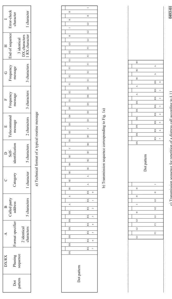
2 Technical format of a call sequence 2.1 The technical format of the call sequence is:
0493-00 Dot
pattern Phasing sequence Format specifier Address Category
Self-identification
* Distress calls only. Dot pattern See § 3 Phasing sequence See § 3 Call content See Tables 4.1 to 4.10.2 Closing sequence See § 9, § 10 and Fig. 1 Symbol No. Phasing and unique functions Format
specifier(1) Category(1) of distressNature (1) telecommandFirst (1) telecommandSecond (1)
121 Reserved for national non-calling purposes e.g. Report ITU-R M.1159 Ship position or location registration updating (6) 122 Ack. BQ (EOS) (6) (6) 123 Individual station semi-automatic/ automatic service (6) (6) 124 (5) (6) (6) 125 Phasing DX position (6) (6) 126 * No information No information 127 EOS (6) (6) TP: telephony TTY: direct printing
ARQ: Rec. ITU-R M.476 or Rec. ITU-R M.625 equipment
(1) Unassigned symbols should be rejected. The DSC equipment should take no action.
(2) Currently unassigned when used with first telecommands other than symbol No. 104 – for future use.
(3) Used for selective call to a group of ships in a specified VTS area (Rec. ITU-R M.825). Reception of calls having format specifier 103, for (or) category shall not activate any alarms on shipborne DSC controller. Should not be used in any future expansion.
(4) Only used for semi-automatic/automatic service.
(5) Used in the automatic VHF/UHF service (Rec. ITU-R M.586). Should not be used in any future expansion.
(6) Should not be used in any future expansion.
(7) MF/HF used only for distress alert acknowledgment and coast station receive (see Table 4).
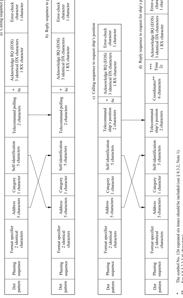
2.2 Examples of typical call sequences and the construction of the transmission format are given in Figs. 1 to 3.
2.3 The flow charts illustrating the operation of the DSC system are shown in Figs. 4 and 5.
3 Dot pattern and phasing
3.1 The phasing sequence provides information to the receiver to permit correct bit phasing and unambiguous determination of the positions of the characters within a call sequence (see Note 1).
NOTE 1 – Acquisition of character synchronization should be achieved by means of character recognition rather than, for example, by recognizing a change in the dot pattern, in order to reduce false synchronization caused by a bit error in the dot pattern.
3.2 The phasing sequence consists of specific characters in the DX and RX positions transmitted alternatively. Six DX characters are transmitted.
3.2.1 The phasing character in the DX position is symbol No. 125 of Table 1.
3.2.2 The phasing characters in the RX position specify the start of the information sequence (i.e. the format specifier) and consist of the symbol Nos. 111, 110, 109, 108, 107, 106, 105 and 104 of Table 1, consecutively.
3.3 Phasing is considered to be achieved when two DXs and one RX, or two RXs and one DX, or three RXs in the appropriate DX or RX positions, respectively, are successfully received. These three phasing characters may be detected in either consecutive or non-consecutive positions but in both cases all bits of the phasing sequence should be examined for a correct 3-character pattern. A call should be rejected only if a correct pattern is not found anywhere within the phasing sequence.
3.4 To provide appropriate conditions for earlier bit synchronization and to allow for scanning methods to monitor several HF and MF frequencies by ship stations, the phasing sequence should be preceded by a dot pattern (i.e. alternating B-Y or Y-B sequence bit synchronization signals) with duration of:
3.4.1 200 bits
At HF and MF for:
– distress alerts;
– distress acknowledgements;
– distress relays addressed to a geographic area;
– distress relay acknowledgements addressed to all ships;
– all calls addressed to a ship station other than those specified in § 3.4.2.
3.4.2 20 bits
At HF and MF, for all acknowledgements to individual calls having format specifiers 120 and 123 and for all calling to coast stations. At VHF for all calls.
4 Format specifier
4.1 The format specifier characters which are transmitted twice in both the DX and RX positions (see Fig. 1) are:
4.1.1 symbol No. 112 for a “distress” alert (RR Appendix 13, Part A3, § 1); or
4.1.2 symbol No. 116 for an “all ships” call; or
4.1.3 symbol No. 114 for a selective call to a group of ships having a common interest (e.g. belonging to one particular country, or to a single ship owner, etc.); or
4.1.4 symbol No. 120 for a selective call to a particular individual station; or
4.1.5 symbol No. 102 for a selective call to a group of ships in a particular geographic area; or
4.1.6 symbol No. 123 for a selective call to a particular individual station using the semi-automatic/automatic service.
4.2 It is considered that receiver decoders must detect the format specifier character twice for “distress” alerts and “all ships” calls to effectively eliminate false alerting. For other calls, the address characters provide additional protection against false alerting and, therefore, single detection of the format specifier character is considered satisfactory (see Table 3).
5 Address
5.1 “Distress” alerts and “all ships” calls do not have addresses since these calls are implicitly addressed to all stations (ship stations and coast stations).
5.2 For a selective call directed to an individual ship, to a coast station or to a group of stations having a common interest, the address consists of the characters corresponding to the station’s maritime mobile service identity, the sequence consisting of characters coded in accordance with Table 2 (see Note 1).
NOTE 1 – According to RR Article 19, maritime mobile service identities are formed of a series of nine digits, consisting of three digits of the Maritime Identification Digits (MID) and six more digits.
These identities are included in the address and self-identification parts of the call sequence and are
transmitted as five characters C5C4C3C2C1, comprising the ten digits of:
(X1, X2) (X3, X4) (X5, X6) (X7, X8) and (X9, X10)
respectively, whereas digit X10 is always the figure 0 unless the equipment is also designed in accordance
with Recommendation ITU-R M.1080.
Example:
MID X4 X5 X6 X7 X8 X9 being the ship station identity is transmitted by the DSC equipment as:
(M, I) (D, X4) (X5, X6) (X7, X8) (X9, 0)
5.3 For a selective call directed to a group of ships in a particular geographic area a numerical geographic coordinates address consisting of ten digits (i.e. 5 characters), is constructed as follows (see Fig. 6 and Note 1):
NOTE 1 – In order to comply with commonly accepted practice, the order of entry and read-out should be: first latitude and then longitude.
5.3.1 the designated geographic area will be a rectangle in Mercator projection;
5.3.2 the upper left-hand (i.e. North-West) corner of the rectangle is the reference point for the area;
5.3.3 the first digit indicates the azimuth sector in which the reference point is located, as follows:
5.3.3.1 quadrant NE is indicated by the digit “0”,
5.3.3.2 quadrant NW is indicated by the digit “1”,
5.3.3.3 quadrant SE is indicated by the digit “2”,
5.3.3.4 quadrant SW is indicated by the digit “3”;
5.3.4 the second and third digits indicate the latitude of the reference point in tens and units of degrees;
5.3.5 the fourth, fifth and sixth digits indicate the longitude of the reference point in hundreds, tens and units of degrees;
5.3.6 the seventh and eighth digits indicate the vertical (i.e. North-to-South) side of the rectangle,
∆ϕ, in tens and units of degrees;
5.3.7 the ninth and tenth digits indicate the horizontal (i.e. West-to-East) side of the rectangle,
∆λ, in tens and units of degrees.
6 Category
6.1 The “category” information is coded as shown in Table 3 and defines the degree of priority of the call sequence.
6.2 For a “distress” alert the priority is defined by the format specifier and no category information is included in the call sequence.
6.2.1 For distress relays, distress relay acknowledgements and distress acknowledgements the category is distress (RR Appendix 13, Part A3, § 25.1).
6.3 For safety related calls, the “category” information specifies:
6.3.1 urgency; or
6.3.2 safety.
6.4 For other calls, the “category” information specifies:
6.4.1 routine.
7 Self-identification
7.1 The maritime mobile service identity (MMSI) assigned to the calling station, coded as indicated in § 5.2 and its Note 1, is used for self-identification.
8 Messages
The messages that are included in a call sequence contain the following message elements, which are listed in the order in which they would appear in each message. All message formats are explicitly defined in Tables 4.1 through 4.10.2:
8.1 For a “distress” alert (see Table 4.1)) the distress information is contained in four messages in the following order:
8.1.1 Message 1 is the “nature of distress” message, coded as shown in Table 3, i.e.:
8.1.1.1 fire, explosion;
8.1.1.2 flooding;
8.1.1.3 collision;
8.1.1.4 grounding;
8.1.1.5 listing, in danger of capsizing;
8.1.1.6 sinking;
8.1.1.7 disabled and adrift;
8.1.1.8 undesignated distress;
8.1.1.9 abandoning ship;
8.1.1.10 piracy/armed robbery attack;
8.1.1.11 man overboard;
8.1.1.12 emergency position-indicating radiobeacon (EPIRB) emission.
8.1.2 Message 2 is the “distress coordinates” message, consisting of ten digits indicating the location of the vessel in distress, coded on the principles described in Table 2, in pairs starting from the first and second digits (see Note 1 to § 5.3):
8.1.2.1 The first digit indicates the quadrant in which the incident has occurred, as follows:
8.1.2.1.1 quadrant NE is indicated by the digit “0”,
8.1.2.1.2 quadrant NW is indicated by the digit “1”,
8.1.2.1.3 quadrant SE is indicated by the digit “2”,
8.1.2.1.4 quadrant SW is indicated by the digit “3”.
8.1.2.2 The next four figures indicate the latitude in degrees and minutes.
8.1.2.3 The next five figures indicate the longitude in degrees and minutes.
8.1.2.4 If “distress coordinates” cannot be included, or if the position information has not been updated for 23½ h, the 10 digits following the “nature of distress” should be automatically transmitted as the digit 9 repeated 10 times.
8.1.3 Message 3 is the time indication (UTC) when the coordinates were valid consisting of four digits coded on the principles described in Table 2, in pairs starting from the first and second digits.
8.1.3.1 The first two digits indicate the time in hours.
8.1.3.2 The third and fourth digits indicate the part of the hours in minutes.
8.1.3.3 If the time cannot be included the four time indicating digits should be transmitted automatically as “8 8 8 8”.
8.1.4 Message 4 is a single character to indicate the type of communication (telephone or FEC teleprinter) which is preferred by the station in distress for subsequent exchange of distress traffic (RR Appendix 13, Part A3, § 25, 1). This character is coded as shown in Table 3 first telecommand.
8.2 For a distress relay, distress relay acknowledgement, distress acknowledgement (see Tables 4.2, 4.3 and 4.4) the distress information is contained in five messages in the following order:
8.2.1 Message 0 is the “MMSI” of the vessel in distress.
8.2.2 Message 1 is the “nature of distress” message, coded as shown in Table 3, i.e.:
8.2.2.1 fire, explosion;
8.2.2.2 flooding;
8.2.2.3 collision;
8.2.2.4 grounding;
8.2.2.5 listing, in danger of capsizing;
8.2.2.6 sinking;
8.2.2.7 disabled and adrift;
8.2.2.8 undesignated distress;
8.2.2.9 abandoning ship;
8.2.2.10 piracy/armed robbery attack;
8.2.2.11 man overboard;
8.2.2.12 emergency position-indicating radiobeacon (EPIRB) emission.
8.2.3 Message 2 is the “distress coordinates” message, consisting of ten digits indicating the location of the vessel in distress, coded on the principles described in Table 2, in pairs starting from the first and second digits (see Note 1 to § 5.3):
8.2.3.1 The first digit indicates the quadrant in which the incident has occurred, as follows:
8.2.3.1.1 quadrant NE is indicated by the digit “0”,
8.2.3.1.2 quadrant NW is indicated by the digit “1”,
8.2.3.1.3 quadrant SE is indicated by the digit “2”,
8.2.3.1.4 quadrant SW is indicated by the digit “3”.
8.2.3.2 The next four figures indicate the latitude in degrees and minutes.
8.2.3.4 If “distress coordinates” cannot be included, or if the position information has not been updated for 23½ h, the 10 digits following the “nature of distress” should be automatically transmitted as the digit 9 repeated 10 times.
8.2.4 Message 3 is the time indication (UTC) when the coordinates were valid consisting of four digits coded on the principles described in Table 2, in pairs starting from the first and second digits.
8.2.4.1 The first two digits indicate the time in hours.
8.2.4.2 The third and fourth digits indicate the part of the hours in minutes.
8.2.4.3 If the time cannot be included the four time indicating digits should be transmitted automatically as “8 8 8 8”.
8.2.5 Message 4 is a single character to indicate the type of communication (telephone or FEC teleprinter) which is preferred by the station in distress for subsequent exchange of distress traffic (RR Appendix 13, Part A3, § 25.1). This character is coded as shown in Table 3 first telecommand.
8.3 For other types of calls (see Table 4.5 through 4.10.2 and Figs. 2 and 3) messages are included in the following order:
8.3.1 Message 1 is the “telecommand” information and consists of 2 characters (first and second telecommand) coded as shown in Table 3;
8.3.1.1 if no information additional to that conveyed by the first telecommand character is required, then the second telecommand signal should be symbol No. 126 (no information) (see Table 3);
8.3.1.2 if no telecommand information is used, symbol No. 126 is transmitted twice.
8.3.1.3 If the telecommand 1 is “F3E/G3E duplex TP” (symbol 101) in a request, which can be complied with, the telecommand 1 “F3E/G3E all modes TP” (symbol 100) should be used in the acknowledgement.
8.3.2 Message 2 may contain two “channel or frequency message” elements, each of which always consists of three characters, “character 1”, “character 2” and “character 3”, indicating the proposed working frequency (in the F1B/J2B mode the assigned frequency should be used) in multiples of 100 Hz or the channel number (coded in accordance with Table 5) or the ship’s position. The first frequency element (the RX field) in the call indicates the called station receive frequency and the second frequency element (the TX field) indicates the called station transmit frequency. In acknowledgements the RX and TX fields indicate the receive and transmit frequency of the acknowledging station respectively (see also Fig. 2 and Note 1).
NOTE 1 – If only one channel or frequency message element is used, this indicates the called station receive channel or frequency or a two-frequency (paired) channel. A second channel or frequency message element may be used to designate the called station transmit channel or frequency. If the calling station indicates only the called station receive frequency (for broadcast mode transmissions) then the symbol No. 126 repeated three times should be transmitted instead of the called station transmit channel or frequency message element. If no “channel or frequency message” elements are used, the symbol No. 126 is transmitted six times. For calls using the semi-automatic/automatic VHF service (see Table 4.10.1) then only one “channel or frequency message” element is transmitted which indicates the paired channel number. In the absence of this element the symbol No. 126 should be transmitted three times.
8.3.2.1 Frequency information
The frequency (in the F1B/J2B mode the assigned frequency should be used) in multiples of 100 Hz may only be indicated as such when the frequency is below 30 MHz. The three characters provide for the required six decimal digits. Character 1 represents the units (U) and tens (T) of 100 Hz, character 2 the hundreds (H) and thousands (M) and character 3 the tens of thousands (TM) and hundreds of thousands (HM) of 100 Hz. For MF/HF DSC, use frequency selection mode, vice channel selection mode, to ensure international interoperability.
8.3.2.2 Channel information 8.3.2.2.1 HF and MF channels
If the HM digit is 3, this indicates that the number represented by the digits TM, M, H, T and U is the HF/MF working channel number (either single frequency or two frequency channels). This mode should only be used for decoding received calls, to ensure interoperability with older equipment.
8.3.2.2.2 VHF channels
If the HM digit is 9, this indicates that the number represented by the values of the digits M, H, T and U is the VHF working channel number. If the M digit is 1, this indicates that the ship stations transmitting frequency is being used as a simplex channel frequency for both ship and coast stations. If the M digit is 2, this indicates that the coast stations transmitting frequency is being used as a simplex channel frequency for both ship and coast stations.
8.3.2.3 Ship’s position information
8.3.2.3.1 For MF/HF calls, Message 2 may contain the ship’s position, consisting of the digit 5 repeated two times and ten digits (five characters) indicating this position, coded in accordance with § 8.1.2 to § 8.1.2.3 (see Table 6).
8.3.2.3.2 For position requests message 2 consists of 6 no information symbols (symbol No. 126).
8.3.2.3.3 In acknowledgements to a call requesting ship’s position (see Fig. 3d)) message 2 consists of twelve digits (six symbols), the first of which should be coded in accordance with § 8.1.2 to § 8.1.2.3 followed by one symbol No. 126.
Message 3 follows message 2 in this case and contains the time (UTC) when the coordinates were valid, coded as indicated in § 8.1.3 to § 8.1.3.3.
8.3.3 Message 3 follows message 2 when using the DSC system for calls initiated by ship stations requiring a semi-automatic or automatic connection (see Table 4.10.1 and 4.10.2) and contains the public switched network number (e.g. telephone number). In this case the format specifier used is symbol No. 123.
8.3.3.1 This number is coded by up to nine symbols in a manner similar to that shown in Table 2, except that the first character transmitted should be either symbol No. 105 or No. 106 to indicate whether the network number contains an odd or even number of significant digits. As an example, the number 0012345 would be coded as symbol numbers 105 00 01 23 45 whereas the number 00123456 should be coded as symbol numbers 106 00 12 3456.
8.4 For “distress relay” including shore-to-ship alerts, “distress relay acknowledgement” and “distress acknowledgement” calls, the message formats are indicated in Tables 4.3, 4.4 and 4.2 respectively.
8.4.1 When sending a distress alert on behalf of another ship which is unable to send its own alert, and where the identity of the station in distress is unknown, the distress relay call should contain the symbol No. 126 transmitted five times for the “identification of the station in distress”.
8.5 Test calls
Test calls on the distress and safety frequencies for MF and HF and VHF channel 70 may be conducted using the test call sequence in Table 4.7.
9 End of sequence
The “end of sequence” (EOS) character is transmitted three times in the DX position and once in the RX position (see Fig. 1b)). It is one of the three unique characters corresponding to symbol Nos. 117, 122 and 127 as follows:
9.1 symbol No. 117 if the call requires acknowledgement (Acknowledge RQ), used for individual and automatic/semiautomatic calls only;
9.2 symbol No. 122 if the sequence is an answer to a call that requires acknowledgement (Acknowledge BQ), used for individual and automatic/semiautomatic calls and all distress relay acknowledgements;
9.3 symbol No. 127 for all other calls.
10 Error-check character
10.1 The error-check character (ECC) is the final character transmitted and it serves to check the entire sequence for the presence of errors which are undetected by the ten-unit error-detecting code and the time diversity employed.
10.2 The seven information bits of the ECC shall be equal to the least significant bit of the modulo-2 sums of the corresponding bits of all information characters (i.e. even vertical parity). The format specifier and the EOS characters are considered to be information characters. The phasing characters and the retransmission (RX) characters shall not be considered to be information characters. Only one format specifier character and one EOS character should be used in constructing the ECC. The ECC shall also be sent in the DX and RX positions.
10.3 Automatic acknowledgement transmissions should not start unless the ECC is received and decoded correctly. A received ECC which does not match that calculated from the received information characters may be ignored if this was due to an error detected in the ten-unit error-detecting code of the information characters which was correctable by use of the time diversity code.
10.4 The receiver decoder should provide maximum utilization of the received signal, including use of the error-check character.
11 Distress alert attempt
11.1 Distress alerts may be transmitted as a single frequency or a multi-frequency call attempt preceded by a dot pattern. MF/HF equipment should be capable of using both single and multi-frequency call attempts. Where a distress alert attempt contains more than one consecutive distress alert on the same frequency (see Recommendation ITU-R M.541, Annex 1, § 3.1.3), these consecutive alerts should be transmitted with no gap between the end of one call and the start of the dot pattern of the following call to enable bit synchronization to be maintained (see Fig. 1c)). Multi-frequency call attempts should always include at least the MF and HF 8 MHz band DSC distress and safety frequencies.
11.2 A distress alert should be activated only by means of a dedicated distress button which should be clearly identified and be protected against inadvertent operation with a spring loaded lid or cover. The initiation of a distress alert should at least require two independent actions.
11.3 Calls with format specifier “distress” or category “distress”, “urgency” and “safety” should be initiated manually only. This applies also for ships equipped for automatic DSC operation. For automatic repetition of distress alerts see Recommendation ITU-R M.541, Annex 1, § 3.1.3 and 3.3.5.
11.4 Immediately following a distress alert a DSC expansion message giving enhanced position resolution according to Recommendation ITU-R M.821 should be transmitted in the following manner.
11.4.1 For a single frequency distress alert attempt the expansion message should be transmitted immediately after the last of five consecutive distress alerts.
11.4.2 For a multi-frequency distress alert attempt the expansion message should be transmitted immediately after each distress alert.
12 Shipborne human machine interface (HMI) 12.1 Shipborne aural alarm
Shipborne alarms should start softly and increase in volume if not silenced by the operator. This will give the operator the opportunity to acknowledge the alarm without interrupting the ship’s current communications.
Distress and urgency calls should have a distinctive two tone alarm. The alarm should consist of two substantially sinusoidal audio-frequency tones, transmitted alternately. One tone should have a frequency of 2200 Hz and the other a frequency of 1300 Hz. The duration of each tone should be 250 ms.
Distress calls and urgency calls should activate an alarm. For HF and MF distress calls, the alarm should activate only when a distress alert, distress acknowledgement, or a distress relay is received and the distress position is within 500 nm (926 km) of the receiving vessel’s position, or if the distress position is in the polar areas (latitude greater than 70° N or 70° S). The alarm should also activate when the call is received and the distance between the vessel in distress and the receiving vessel cannot be determined. (NOTE – Disabling of aural alarm does not affect handling of call.)
For geographic area calls, the alarm appropriate to the category should activate when the receiving station’s position is within the area specified by the call or the receiving station’s position is not known. The alarm should not be activated where duplicate distress relay calls are received within one hour. A duplicate distress relay call is one having format specifier all ships or geographic area that contains identical message information, as defined in § 8.1 and an identical distress MMSI.
12.2 Inactivity timer
During normal operation, the equipment should include an inactivity timer to return the DSC system display to default or standby mode if the operator is in a menu where DSC call reception is disabled and does not make any selections or changes for 10 min.
12.3 Display
The information on the display should be visible in all shipboard lighting conditions. It should have the means to display, in plain language with a minimum of 160 characters in two or more lines, the information contained in the received call.
12.4 MMSI
DSC equipment should not transmit any DSC call until own ship’s MMSI allocated to the ship by the relevant administration has been configured and stored in the DSC equipment. Once stored, it should not be possible for the user to change the MMSI number without advise from the manufacturer.
The DSC equipment should display own ship’s MMSI on start-up unless the MMSI has not been configured. If the MMSI has not been configured, the equipment will display a warning that the unit will not transmit any DSC calls until own ship’s MMSI is entered. The equipment should stay in this state until the operator confirms he has read the display.
The MMSI should be readily displayed on the HMI when the DSC equipment is on.
12.5 Disabling of DSC automatic channel switching function on VHF
Automatic switching to a subsequent communications channel on receipt of a DSC call might in some cases disrupt important ongoing communications. Where such capability exists, a means for disabling that function should therefore be provided for all calls other than individual station calls of category distress or urgency. The DSC equipment should provide visual indication that the automatic switching function is disabled.
12.6 Data interface
DSC equipment should be provided with facilities for exchange of data from shipborne navigational equipment or systems, or other shipborne equipment as necessary in accordance with IEC 61162 for purposes including automatic position updating.
12.7 Position updating
DSC equipment should accept valid IEC 61162 position information including the time at which the position was determined, from an external source utilizing the data interface described in § 12.6, for automatic update of own ship’s DSC position.
The DSC equipment may also be provided with an internal electronic position fixing device. In which case, the DSC equipment should automatically switch to the internal source if the external IEC 61162 position information is not valid or not available.
If the automatic position update is not available, a displayed and audible reminder to manually update the position should occur before the position information is 4 h old. The displayed reminder should remain until position updating has been carried out. Any position information not updated for more than 23½ h should automatically be erased.
Own ship’s DSC position information and the source of that information (external, internal, or manually entered) should be displayed on the DSC equipment.
12.8 Geographic area entry
DSC equipment should be provided with means for transforming a geographical area specified by the user as a centre point and a range to the corresponding Mercator area call format specified in § 5.3. The centre point should default to the ships position information and the range should default to 500 nm (926 km). The transformation of the entered range and centre-point should result in the minimum rectangular area that encompasses the entered data.
12.9 Medical transport and neutral ships and aircraft
The capability of using second telecommands “Ships and Aircraft according to Resolution 18” and “Medical Transports” should not be available by default but only after changing relevant parameters in the setup menu.
04 93-01 G2 G3 H I H H DX DX DX DX DX DX A A B 1 B 2 B 3 F 3 G 1 G 2 G 3 H I RX RX RX RX RX RX RX RX A A 76 5 4 3 210 G1 F2 DX DX DX DX DX DX A A B 1 B 2 B 3 B 4 B 5 C D1 D2 D3 D4 D5 E 1 E 2 F 1 F 2 F 3 G1 G2 G3 H I H H RX RX RX RX RX RX RX A A B1 B2 B3 B4 B5 6 7 543 210 C D 1D 2D 3 D 4D 5 E 1 E 2 F 1 F 2 F 3 G 1G 2 G 3 H I RX DX/ RX A B C D E F G H I FI G U RE 1 C ons tr uc ti on of ca ll se qu en ce Do t p at te rn c) Tra ns m is si on s eq uen ce f or re pet it io n of a di st re ss ca ll ac cor di ng to § 11 b) Tra ns m is si on s eq uen ce c or re sp ond in g to F ig . 1a) Do t p at te rn Do t pa tt er n Ph as in g se qu enc e Fo rm at sp ec if ie r 2 i den ti ca l ch ar ac te rs Ca ll ed p ar ty ad dr es s 5 ch ar ac te rs Ca te gor y 1 ch ar ac te r Se lf -id en ti fi ca tio n 5 ch ar ac te rs Te le co mma nd me ss ag e 2 ch ar ac te rs Fr eq uen cy me ss ag e 3 ch ar ac te rs Fr eq uen cy me ss ag e 3 ch ar ac te rs En d of se qu enc e 3 i den ti ca l D X ch ar act er s 1 R X ch ar ac te r 1 ch ar ac te r E rro r-ch ec k ch ar ac te r a) T ech ni ca l fo rm at o f a ty pi ca l ro ut in e m es sa ge
04 93-02 FI GURE 2 E xam pl es o f a ca lli ng s eque nc e and r ep ly s eque nc es f or t ypi ca l i ndi vi dual c al ls Do t pat te rn Fo rm at s pe cif ie r 2 id en tic al cha rac te rs A ddr es s 5 char act er s C at egor y 1 char act er Se lf -i de nt if ic at io n 5 char act er s T ele co mma nd and f requ ency 8 char act er s T ele co mma nd and f requ ency 8 char act er s A cknow le dge R Q ( E O S) 3 i de nt ical D X char act er s 1 R X cha ract er Er ro r-ch ec k cha rac te r 1 char act er Pha si ng se quenc e a) C al ling sequ ence b) R epl y s eque nce w ith conf ir m at io n c) R epl y s eque nce w ith new pr opos al d) R epl y s eque nce w ith r ef us al Do t pat te rn Pha si ng se quenc e Fo rm at s pe cif ie r 2 id en tic al cha rac te rs A ddr es s 5 char act er s C at egor y 1 char act er Se lf -i de nt if ic at io n 5 char act er s A cknow le dge B Q ( E O S) 3 i de nt ical D X char act er s 1 R X cha ract er Er ro r-ch ec k cha rac te r 1 char act er Er ro r-ch ec k cha rac te r 1 char act er A cknow le dge B Q ( E O S) 3 i de nt ical D X char act er s 1 R X cha ract er A cknow le dge B Q ( E O S) 3 i de nt ical D X char act er s 1 R X cha ract er T ele co mma nd and f requ ency 8 char act er s T ele co mma nd and f requ ency 8 char act er s C at egor y 1 char act er C at egor y 1 char act er Se lf -i de nt if ic at io n 5 char act er s Se lf -i de nt if ic at io n 5 char act er s Do t pat te rn Do t pat te rn Pha si ng se quenc e Pha si ng se quenc e Fo rm at s pe cif ie r 2 id en tic al cha rac te rs Fo rm at s pe cif ie r 2 id en tic al cha rac te rs A ddr es s 5 char act er s A ddr es s 5 char act er s Er ro r-ch ec k cha rac te r 1 char act er
04 93-03 FI GURE 3 C al lin g s eque nc es and r epl y s eque nc es f or pol lin g a nd s hi p’ s po si ti on Do t pat te rn Fo rm at s pe cif ie r 2 id en tic al cha rac te rs A ddr es s 5 char act er s C at egor y 1 char act er Se lf -i de nt if ic at io n 5 char act er s T el eco m m and pol ling 2 char act er s A cknow le dge R Q ( E O S) 3 i de nt ical D X char act er s 1 R X cha ract er Er ro r-ch ec k cha rac te r 1 char act er Pha si ng se quenc e a) C al ling s equ ence pol ling b) R epl y s eque nce t o po lli ng c) C al ling s equ ence to r eque st s hi p’ s pos iti on d) R epl y s eq uenc e to r eq ues t f or s hi p’ s pos iti on Do t pat te rn Pha si ng se quenc e Fo rm at s pe cif ie r 2 id en tic al cha rac te rs A ddr es s 5 char act er s C at egor y 1 char act er Se lf -i de nt if ic at io n 5 char act er s A cknow le dge B Q ( E O S) 3 i de nt ical D X char act er s 1 R X cha ract er Er ro r-ch ec k cha rac te r 1 char act er Er ro r-ch ec k cha rac te r 1 char act er A cknow le dge R Q ( E O S) 3 i de nt ical D X char act er s 1 R X cha ract er A cknow le dge B Q ( E O S) 3 i de nt ical D X char act er s 1 R X cha ract er T ele co mma nd sh ip ’s p os itio n 2 char act er s C at egor y 1 char act er C at egor y 1 char act er Se lf -i de nt if ic at io n 5 char act er s Se lf -i de nt if ic at io n 5 char act er s Do t pat te rn Do t pat te rn Pha si ng se quenc e Pha si ng se quenc e Fo rm at s pe cif ie r 2 id en tic al cha rac te rs Fo rm at s pe cif ie r 2 id en tic al cha rac te rs A ddr es s 5 char act er s A ddr es s 5 char act er s Er ro r-ch ec k cha rac te r 1 char act er T el eco m m and pol ling 2 char act er s * 6c * 6c * 6c Coor di na te s* * 6 char act er s *** Tim e 2c T ele co mma nd sh ip ’s p os itio n 2 char act er s * T he s ym bol N o. 126 r epe at ed si x tim es s ho ul d be i ncl ud ed ( se e § 8. 3. 2, N ot e 1) . ** See § 8. 3. 2. 3. 3 (6 char act er s) . *** See § 8. 3. 2. 3. 2 ( 2 char act er s) .
0493-04 FIGURE 4
Example of operational flow chart Transmitting Message composition* Transmit message Receiving Operation in general No (Yes) Yes (No) Branching (decision) Manual operation Beginning or end of the procedures
This method may be used when either single channel receivers (without scanning) or multi-channel receivers are used. This method is preferable when scanning receivers are used on DSC channels.
Message composition flow chart is shown in Fig. 5b. Acknowledge BQ AcknowledgeRQ Scanning? Address error free? Address corresponds to a stored address? Receive and process
message Store message
Receive message Message received error free? Address corresponds to a stored address? No Yes Yes Received ECC matches? Indicate ECC error No Read information of received message Yes Yes(2) No No Safety related? End of sequence Yes Procedures as given in RR No Message composition Message composition with unable to comply Message composition with acknowledge BQ Transmit message End Wait on working frequency/ channel Able to comply? All acceptable? No
Yes Message composition*
Yes Yes Message composition with new proposal No(1) * (1) (2) No Yes No
0493-05
FIGURE 5
Example of message composition flow chart Distress
Area Group sequencesSpecial
Select address* Enter self-identification** Individual address* Group address* Area address* Enter nature of distress Include nature of dis-tress? Yes No Routine
Safety identification**Enter self- Urgency Distress
Acknowl-edge reply? Distress coordinates available? Yes No No Additional information? All acceptable? Enter distress coordinates and time *** Enter telecommand information Processor copies message No No No Yes Tele-command infor-mation? Yes Specify telecommand information? Specify receiver frequency information Receiver frequency infor-mation? Transmitter frequency infor-mation? Yes No Specify transmitter frequency information No No No Enter ship’s position*** Enter telephone number Ship’s position infor-mation? Semi-automatic/ automatic ship-to-shore required? Acknowl-edge RQ or BQ? RQ BQ End of sequence Processor adds acknowledge BQ Processor adds end of sequence End of message Yes Yes Yes Yes Yes
For reply message, processor copies self-identification of received message. The self-identification of a calling sequence is automatically entered. This may be entered automatically. * ** *** Processor adds acknowledge RQ Individual
Individual* Area Group*
Distress ACK/relay, urgency, safety
All ships
Select address*
0493-06 –15° –20° 15° 20° a –15° –10° –5° –5° –10° E N S c –20° 10° 5° 0° 5° 10° b ϕc λc ∆ϕ ∆λ 2 1 1 0 1 2 0 3 0 5 1 2 0 0 1 0 1 0 1 1 1 0 0 2 0 2 0 3 0 0 a) b) c) ϕa λa ∆ϕ ∆λ ∆ϕ = 3° ∆λ= 5° ∆ϕ = 10° ∆λ = 10° ∆ϕ = 20° ∆λ = 30° FIGURE 6 Geographic coordinates W Format specifier Category Category Category Sector ϕa = – 11° (South) λa= 12° (East) ϕb = – 10° (South) λb = 10° (East) ϕc = 10° (North) λc = – 20° (West) Format specifier Format specifier
Legend for Tables 4.1 to 4.10.2
Symbol/expression Meaning
Required
Required for backward compatibility
Symbols 100-127 Symbols in accordance with Table 3
Area Coded in accordance with Annex 1, § 5.3
Frequency Coded in accordance with Annex 1, § 8.2.2
MMSI Coded in accordance with Annex 1, § 5.2
Pos1 Coded in accordance with Annex 1, § 8.1.2
Pos2 Coded in accordance with Annex 1, § 8.3.2.3.1
Pos3 Coded in accordance with Annex 1, § 8.3.2.3.2
Pos4 Coded in accordance with Annex 1, § 8.3.2.3.3
Pos5 Coded in accordance with Recommendation ITU-R M.821
UTC Coded in accordance with Annex 1, § 8.1.3
n/a This field is not included in this call
ECC Coded in accordance with Annex 1, § 10.2
expan1 Expansion sequence 1
expan2 Expansion sequence 2
expan3 Expansion sequence 3
Does not apply
Rec.
ITU-R M.493-11
25
TABLE 4.1 Distress alerts
Applicable to Technical format of call sequence
Message 1 2 3 4 Ship station Class A/B Ship station Class D Ship station
Class E Coast station Frequency band Type Tx Rx Tx Rx Tx Rx Tx Rx Format specifier (2 identical) Self-ID (5) Nature of distress (1) Distress coordi-nates (5) Time (2) Subse-quent commu-nications (1) EOS (1) ECC (1) EOS (2 identical) Rec. ITU-R M.821 expansion sequence (9) Détresse (RT)
112 MMSI 100 to 111 Pos1 UTC 100 127 ECC 127 expan1
VHF
Détresse (RLS)
112 MMSI 112 Pos1 UTC 126 127 ECC 127 expan1
Détresse (RT)
112 MMSI 100 to 111 Pos1 UTC 109 127 ECC 127 expan1
MF/HF
Détresse (CED)
112 MMSI 100 to 111 Pos1 UTC 113 127 ECC 127 expan1
Rec. ITU-R M.821 expansion sequence
Type Expansion data specifier (1) Enhanced position resolution (4) EOS (1) ECC (1) (2 identical) EOS
Rec.
ITU-R M.493-11
TABLE 4.2
Distress acknowledgements
Applicable to Technical format of call sequence
Message 0 1 2 3 4 Ship station Class A/B Ship station Class D Ship station Class E Coast station Frequency band Type Tx Rx Tx Rx Tx Rx Tx Rx Format specifier (2
iden-tical) Category(1) Self-ID(5) Tele-command (1) Distress MMSI (5) Nature of distress (1) Distress coordi-nates (5) Time(2) Subse-quent commu-nications (1) EOS
(1) ECC (1) (2 identical)EOS
Rec. ITU-R M.821 expansion sequence (9) VHF Distress
acknowl-edgement (RT) 116 112 MMSI 110 MMSI 100 to 111 Pos1 UTC 100 127 ECC 127 expan1
Distress
acknowl-edgement (EPIRB) 116 112 MMSI 110 MMSI 112 Pos1 UTC 126 127 ECC 127 expan1
MF Distress
acknowl-edgement (RT) 116 112 MMSI 110 MMSI 100 to 111 Pos1 UTC 109 127 ECC 127 expan1
Distress
acknowl-edgement (FEC) 116 112 MMSI 110 MMSI 100 to 111 Pos1 UTC 113 127 ECC 127 expan1
HF Distress
acknowl-edgement (RT) 116 112 MMSI 110 MMSI 100 to 111 Pos1 UTC 109 127 ECC 127 expan1
Distress
acknowl-edgement (FEC) 116 112 MMSI 110 MMSI 100 to 111 Pos1 UTC 113 127 ECC 127 expan1
The message should match the received distress alert information, except for manually generated
distress acknowledgements by coast stations.
Rec. ITU-R M.821 expansion sequence
Type Expansion data specifier (1) Enhanced position resolution (4) EOS (1) ECC (1) (2 identical) EOS
Rec.
ITU-R M.493-11
27
TABLE 4.3 Distress relays
Applicable to Technical format of call sequence
Message 0 1 2 3 4 Ship station Class A/B Ship station Class D Ship station Class E Coast station Frequency band Type Tx Rx Tx Rx Tx Rx Tx Rx Format specifier (2 identical) Address (5) Category (1) Self-ID (5) Tele-command (1) Distress MMSI (5) Nature of distress (1) Distress coordinates (5) Time (2) Subse-quent commu- nica-tions (1) EOS (1) ECC (1) EOS (2 iden-tical) Rec. ITU-R M.821 expansion sequence (9)
VHF Individual (RT) 120 MMSI 112 MMSI 112 MMSI 100 to 111 Pos1 UTC 100 117 ECC 117 expan2
Individual
(EPIRB) 120 MMSI 112 MMSI 112 MMSI 112 Pos1 UTC 126 117 ECC 117 expan2
Geographic area
(RT) 102 Zone 112 MMSI 112 MMSI 100 à 111 Pos1 UTC 100 127 ECC 127 expan1
Geographic area
(EPIRB) 102 Zone 112 MMSI 112 MMSI 112 Pos1 UTC 126 127 ECC 127 expan1
All ships (RT) 116 n/a 112 MMSI 112 MMSI 100 to 111 Pos1 UTC 100 127 ECC 127 expan1
All ships (EPIRB) 116 n/a 112 MMSI 112 MMSI 112 Pos1 UTC 126 127 ECC 127 expan1
MF/HF Individual (RT) 120 MMSI 112 MMSI 112 MMSI 100 to 111 Pos1 UTC 109 117 ECC 117 expan2
Individual (FEC) 120 MMSI 112 MMSI 112 MMSI 100 to 111 Pos1 UTC 113 117 ECC 117 expan2
Geographic area
(RT) 102 Zone 112 MMSI 112 MMSI 100 to 111 Pos1 UTC 109 127 ECC 127 expan1
Geographic area
Rec.
ITU-R M.493-11
TABLE 4.3 (end)
Applicable to Technical format of call sequence
Message 0 1 2 3 4 Ship station Class A/B Ship station Class D Ship station Class E Coast station Frequency band Type Tx Rx Tx Rx Tx Rx Tx Rx Format specifier (2 identical) Address (5) Category (1) Self-ID (5) Tele-command (1) Distress MMSI (5) Nature of distress (1) Distress coordinates (5) Time (2) Subse-quent commu- nica-tions (1) EOS (1) ECC (1) EOS (2 iden-tical) Rec. ITU-R M.821 expansion sequence (9)
All ships (RT) 116 n/a 112 MMSI 112 MMSI 100 to 111 Pos1 UTC 109 127 ECC 127 expan1
MF/HF (end)
All ships (FEC) 116 n/a 112 MMSI 112 MMSI 100 to 111 Pos1 UTC 113 127 ECC 127 expan1
The message should match the received distress alert information, except for manually generated relays
observed or notified by non-DSC means.
Rec. ITU-R M.821 expansion sequence
Type Expansion data specifier (1) Enhanced position resolution (4) EOS (1) ECC (1) (2 identical) EOS
expan1 100 Pos5 127 ECC 127
Rec.
ITU-R M.493-11
29
TABLE 4.4
Distress relay acknowledgements
Applicable to Technical format of call sequence
Message 0 1 2 3 4 Ship station Class A/B Ship station Class D Ship station Class E Coast station Frequency band Type Tx Rx Tx Rx Tx Rx Tx Rx Format specifier (2 identical) Address (5) Cate-gory (1) Self-ID (5) Tele-command (1) Distress MMSI (5) Nature of distress (1) Distress coordinates (5) Time(2) Subse-quent commu- nica-tions (1) EOS (1) ECC (1) EOS (2 iden-tical) Rec. ITU-R M.821 expansion sequence (9)
VHF Individual (RT) 120 MMSI 112 MMSI 112 MMSI 100 to 111 Pos1 UTC 100 122 ECC 122 expan3
Individual (EPIRB) 120 MMSI 112 MMSI 112 MMSI 112 Pos1 UTC 126 122 ECC 122 expan3
All ships (RT) 116 n/a 112 MMSI 112 MMSI 100 to 111 Pos1 UTC 100 122 ECC 122 expan3
All ships (EPIRB) 116 n/a 112 MMSI 112 MMSI 112 Pos1 UTC 126 122 ECC 122 expan3
Individual (RT) 120 MMSI 112 MMSI 112 MMSI 100 to 111 Pos1 UTC 109 122 ECC 122 expan3
MH/HF
Individual (FEC) 120 MMSI 112 MMSI 112 MMSI 100 to 111 Pos1 UTC 113 122 ECC 122 expan3
All ships (RT) 116 n/a 112 MMSI 112 MMSI 100 to 111 Pos1 UTC 109 122 ECC 122 expan3
All ships (FEC) 116 n/a 112 MMSI 112 MMSI 100 to 111 Pos1 UTC 113 122 ECC 122 expan3
The message should match the received distress relay call information.
Rec. ITU-R M.821 expansion sequence
Type Expansion data specifier (1) Enhanced position resolution (4) EOS (1) ECC (1) (2 identical) EOS
Rec.
ITU-R M.493-11
TABLE 4.5
Urgency and safety calls – All ships
Applicable to Technical format of call sequence
Message 1 2 Ship station Class A/B Ship station Class D Ship station Class E Coast station Frequency band Type Tx Rx Tx Rx Tx Rx Tx Rx Format specifier (2 identical) Category (1) Self-ID (5) 1st tele-command (1) 2nd tele-command (1) Frequency(6) EOS (1) ECC (1) EOS (2 identical)
VHF All modes RT 116 108 or 110 MMSI 100 126 Frequency 127 ECC 127
Duplex RT1 116 108 or 110 MMSI 101 126 Frequency 127 ECC 127
Medical transports 116 110 MMSI 100 111 Frequency 127 ECC 127
Ships and aircraft
(Res. 18) 116 110 MMSI 100 110 Frequency 127 ECC 127
J3E RT 116 108 or 110 MMSI 109 126 Frequency 127 ECC 127
MF/HF
F1B FEC 116 108 or 110 MMSI 113 126 Frequency 127 ECC 127
Rec.
ITU-R M.493-11
31
TABLE 4.6
Urgency and safety – Geographic area calls
Applicable to Technical format of call sequence
Message 1 2 Ship station Class A/B Ship station Class D Ship station Class E Coast station Frequency band Type Tx Rx Tx Rx Tx Rx Tx Rx Format specifier (2 identical) Address (5) Category (1) Self-ID (5) 1st tele-command (1) 2nd tele-command (1) Frequency(6) EOS (1) ECC (1) EOS (2 identical)
MF/HF J3E (RT) 102 Area 108 or 110 MMSI 109 126 Frequency 127 ECC 127
F1B (FEC) 102 Area 108 or 110 MMSI 113 126 Frequency 127 ECC 127
Medical transports 102 Area 110 MMSI 109 or 113 111 Frequency 127 ECC 127
Ships and aircraft
Rec.
ITU-R M.493-11
TABLE 4.7
Urgency and safety – Individual calls and their acknowledgements
Applicable to Technical format of call sequence
Message 1 2 3 Ship station Class A/B Ship station Class D Ship station Class E Coast station Frequency band Type Tx Rx Tx Rx Tx Rx Tx Rx Format specifier (2 identical) Address (5) Category (1) Self-ID (5) 1st tele-command (1) 2nd tele-command (1) Frequency or pos number (6) Time (2) EOS (1) ECC (1) EOS (2 identical)
VHF All modes RT 120 MMSI 108 or 110 MMSI 100 126 Frequency n/a 117 ECC 117
Duplex RT1 120 MMSI 108 or 110 MMSI 101 126 Frequency n/a 117 ECC 117
RT
acknowledgement 120 MMSI 108 or 110 MMSI 100 126 Frequency n/a 122 ECC 122
Unable to comply
acknowledgement 120 MMSI 108 or 110 MMSI 104 100 to 109 Frequency n/a 122 ECC 122
Position request 120 MMSI 108 MMSI 121 126 Pos3 n/a 117 ECC 117
Position
acknowledgement 120 MMSI 108 MMSI 121 126 Pos4 UTC 122 ECC 122
Test 120 MMSI 108 MMSI 118 126 126 n/a 117 ECC 117
Test
acknowledgement 120 MMSI 108 MMSI 118 126 126 n/a 122 ECC 122
Rec.
ITU-R M.493-11
33
TABLE 4.7 (end)
Applicable to Technical format of call sequence
Message 1 2 3 Ship station Class A/B Ship station Class D Ship station Class E Coast station Frequency band Type Tx Rx Tx Rx Tx Rx Tx Rx Format specifier (2 identical) Address (5) Category (1) Self-ID (5) 1st tele-command (1) 2nd tele-command (1) Frequency or pos number (6) Time (2) EOS (1) ECC (1) (2 identical) EOS
MF/HF J3E RT 120 MMSI 108 or 110 MMSI 109 126 Frequency n/a 117 ECC 117
J3E RT with pos
number 120 MMSI 108 or 110 MMSI 109 126 Pos2 n/a 117 ECC 117
J3E RT
acknowledgement 120 MMSI 108 or 110 MMSI 109 126 Frequency n/a 122 ECC 122
F1B FEC or ARQ 120 MMSI 108 or 110 MMSI 113 or 115 126 Frequency n/a 117 ECC 117
F1B FEC or ARQ
with pos number 120 MMSI 108 or 110 MMSI 113 or 115 126 Pos2 n/a 117 ECC 117
F1B FEC or ARQ
acknowledgement 120 MMSI 108 or 110 MMSI 113 or 115 126 Frequency n/a 122 ECC 122
Unable to comply
acknowledgement 120 MMSI 108 or 110 MMSI 104 100 to 109 Frequency n/a 122 ECC 122
Position request 120 MMSI 108 MMSI 121 126 Pos3 n/a 117 ECC 117
Position
acknowledgement 120 MMSI 108 MMSI 121 126 Pos4 UTC 122 ECC 122
Test 120 MMSI 108 MMSI 118 126 126 n/a 117 ECC 117
Test
Rec.
ITU-R M.493-11
TABLE 4.8 Routine group calls
Applicable to Technical format of call sequence
Message 1 2 Ship station Class A/B Ship station Class D Ship station Class E Coast station Frequency band Type Tx Rx Tx Rx Tx Rx Tx Rx Format specifier (2 identical) Address (5) Category (1) Self-ID (5) 1st tele-command (1) 2nd tele-command (1) Frequency(6) EOS (1) ECC (1) EOS (2 identical)
All mode RT 114 MMSI 100 MMSI 100 126 Frequency 127 ECC 127
VHF
Duplex RT1 114 MMSI 100 MMSI 101 126 Frequency 127 ECC 127
J3E RT 114 MMSI 100 MMSI 109 126 Frequency 127 ECC 127
MF/HF
F1B FEC 114 MMSI 100 MMSI 113 126 Frequency 127 ECC 127
Rec.
ITU-R M.493-11
35
TABLE 4.9
Routine individual calls and their acknowledgements
Applicable to Technical format of call sequence
Message 1 2 Ship station Class A/B Ship station Class D Ship station Class E station Coast Frequency band Type Tx Rx Tx Rx Tx Rx Tx Rx Format specifier (2 identical) Address (5) Category (1) Self-ID (5) 1st tele-command (1) 2nd tele-command (1) Frequency or pos number (6) EOS (1) ECC (1) EOS (2 identical)
VHF All mode RT 120 MMSI 100 MMSI 100 126 Frequency 117 ECC 117
Duplex RT1 120 MMSI 100 MMSI 101 126 Frequency 117 ECC 117
RT acknowledgement 120 MMSI 100 MMSI 100 126 Frequency 122 ECC 122
Data 120 MMSI 100 MMSI 106 126 Frequency 117 ECC 117
Data acknowledgement 120 MMSI 100 MMSI 106 126 Frequency 122 ECC 122
Unable to comply
acknowledgement 120 MMSI 100 MMSI 104 100 to 109 Frequency 122 ECC 122
Polling 120 MMSI 100 MMSI 103 126 126 117 ECC 117
Polling acknowledgement 120 MMSI 100 MMSI 103 126 126 122 ECC 122
Rec.
ITU-R M.493-11
TABLE 4.9 (end)
Applicable to Technical format of call sequence
Message 1 2 Ship station Class A/B Ship station Class D Ship station Class E Coast station Frequency band Type Tx Rx Tx Rx Tx Rx Tx Rx Format specifier (2 identical) Address (5) Category (1) Self-ID (5) 1st tele-command (1) 2nd tele-command (1) Frequency or pos number (6) EOS (1) ECC (1) EOS (2 identical)
J3E RT 120 MMSI 100 MMSI 109 126 Frequency 117 ECC 117
MF/HF
J3E RT with pos number 120 MMSI 100 MMSI 109 126 Pos2 117 ECC 117
J3E RT acknowledgement 120 MMSI 100 MMSI 109 126 Frequency 122 ECC 122
F1B FEC, ARQ or data 120 MMSI 100 MMSI 113, 115, 106 126 Frequency 117 ECC 117
FEC, ARQ or data with pos
number 120 MMSI 100 MMSI 113, 115, 106 126 Pos2 117 ECC 117
F1B FEC, ARQ or data
acknowledgement 120 MMSI 100 MMSI 113, 115, 106 126 Frequency 122 ECC 122
Unable to comply
acknowledgement 120 MMSI 100 MMSI 104 100 à 109 Frequency 122 ECC 122
Polling 120 MMSI 100 MMSI 103 126 126 117 ECC 117