CHAPTER
12
DIGITAL TRANSMISSION
AND CODING TECHNIQUES
12.1 INTRODUCTION
Communications systems transmit signals by means of a number of coding tech-niques-electrical or optical. In this chapter, we review some of these techniques. Keep in mind that although in electrical transmission voltages may swing between a negative and a positive level, in optical transmission light may change between a no-light condition to some no-light intensity level; that is, there is negative voltage but no negative light.
When light intensity is modulated between two amplitude values, the modula-tor is known as "amplitude modulamodula-tor." Alternatively, the phase of light may be mod-ulated between two (angular) values (phase-shift modulator), or the frequency of light between two values (frequency-shift modulator); see also section 6.14.
12.2 RETURN TO ZERO AND NON-RETURN TO ZERO
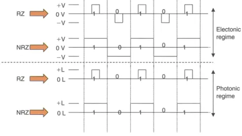
Figure 12.1 illustrates the return-to-zero (RZ) coding and the non-return to zero (NRZ). With either method, the signal alternates between a positive(+V) and a neg-ative (- V) voltage. Logic 1 represents the signal at positive voltage and logic 0 the signal at negative. However, in the NRZ method, transitions from logic 0 to logic 1, and vice versa, directly cross the zero voltage level, whereas in the RZ method, tran-sitions stay temporarily on the zero voltage level.
In optical communications, the terms RZ and NRZ are used differently. Because there is no negative light, NRZ means that a bit of logical value 1 (a pulse of light) changes its value (from light to no-light or vice versa) at the boundaries of the bit pe-riod. Conversely, RZ indicates that the pulse of light is narrower than the bit pepe-riod. 167
168 Part III Coding Optical Information +V -RZ
c=:>
0 V ---+---,+--,--+-,>J- -r--'--'-'t-'--+-~----i---L1-..L...-;'--- V -Electonic regime RZ ~ NRZC=:> +V -NRZ~ 0 V - --+--+---+---1:}----+-+-+-...l.L--+-+- j V j --- --- -l-- --- --t-- -- - --f---- - -~---- -- -+- ---f--- -+L-o
LI
-- -+--+-- -+--B----!- 'l--+---'-'---+--4--- +--~~~~~iC
+L -OLFigure 12.1 RZ and NRZ coding.
In an optical signal, a logic I on for about one-third of the bit period and is off for about two-thirds. A logic 0 remains off for two-thirdsof the bit period.
12.3 UNIPOLAR AND BIPOLAR SIGNALS
A bipolar signal is a three-voltage-level signal that typically swings between a pos -itive and a negative voltage (Figure 12.2). Bipolar signalsmay be RZ or NRZ. In a digital bipolar signal, the ones alternate between the two voltages,positive and neg-ative.This results in a zero-de component on the transmission line.
A unipolarsignal is a two-level signal that typically swings between zero and a positive level. A unipolar signal is considered to be an on-off signal that may be ap-plied to either electrical or optical signals.In electrical transmission, assuming that
+V-Unipolarsignal ,---1\.
~ OV- o
+V Bipolarsignal
q
0 V -VFigure 12.2 Unipolar and bipolar coding.
Chapter 12 Digital Transmission and Coding Techniques 169 statistically there is an equal number of ones and zeros, then there is a de component that may reach half the peak.positive voltage. For transmission over long distances, this de component is undesirable. In optical transmission, a unipolar signal is also known as on-off keying (see Section 12.5).
Another category is the multilevel signal. In this case, several voltage levels (e.g., 8) may be used, each level corresponding to one of eight codes. Although mul-tilevel signals are attractive because of their inherent code compression properties, nevertheless they are not used for transmission in communications networks. In op-tical transmission, multilevel signals do not exist. However, the author has defined methods that use multiwavelength signals.
12.4 48/58, 88/108 CODING
The 4B/5B code translates 4 bits into one of 16 predetermined 5-bit codes. Thus, even if the original 4-bit code is 0000, it is translated to a 5-bit not-all-zero code. This method avoids having all zeros in any code. It may also be designed such that consecutive patterns avoid certain strings of ones. The 4B/5B implies that an initial 1 Gb/s bit rate, after the conversion, has been increased to 1.25 Gb/s because of the added bit. That is, there is 25% overhead bandwidth penalty. Similarly, the 8B/10B code translates 8 bits into one of 256 predetermined 10-bit codes. The bandwidth penalty is also 25%.
12.5 ASK FORMAT
Amplitude-shift keying (ASK) is a technique that uses an electrical bit stream (the modulating frequency) to modulate the intensity of a light beam (the carrier) directly. The carrier has its maximum amplitude for bits having the value "I" and its minimum or zero amplitude for bits having the value "0." This, examined at the unipolar signal case (see Figures 12.1 and 12.2) is also known as on-off
key-ing(OOK).
There are two ASK variations: RZ, by which the signal returns to zero at every symbol (1, 0), and NRZ, by which it does not (see Figure 12.1, photonic regime).
The ASK format can be used in coherent or in IM/DD systems. However, when a semiconductor laser is directly modulated, the signal phase also shifts..In IMIDD detection, phase shift is unimportant. Coherent detection, however, requires constant phase, and thus the amplitude is externally modulated by means of a titanium-diffused LiNb03 waveguide in a Mach-Zehnder configuration (Figure 12.3) or a
semiconductor directional coupler based on electroabsorption multiple quantum well (MQW) properties and structures (Figure 12.4).
170 Part III CodingOpticalInformation
Contact
Mach-Zehnderexternalmodulator Figure 12.3 In coherent detection the amplitude
is externally modulatedbymeansof
a titanium-diffused LiNb03 M
ach-Zehnder waveguide. Contact Fiber P-type MOW N-type Fiber
Semiconductor MOW external modulator
Figure 12.4 In coherent detectiontheamplitudeis externallymodulatedby meansofan MQW directional coupler.
12.6 PSK FORMAT
Phase-shift keying (PSK) is a technique that modulates the phase of a light beam (the carrier) while the frequency and amplitude remain constant during all bits, thus achieving the appearance of a continuous light wave.For binary PSK, the phase is 0°or 180°.For multilevel PSK,the change may be in increments of, for example,45° (8 levels).PSK is a coherent technique.
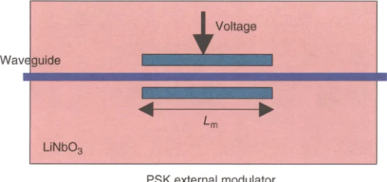
PSK isimplemented externally by passing the light beam through a device known as an electrorefraction modulator; when a voltage is applied to the beam, its refractive index changes. Such devices are made with electro-optic crystals with proper orientation, such as LiNb030 The phase difference is ex-pressed by
Chapter 12 DigitalTransmission and Coding Techniques
Voltage ~, Waveguide
PSK external modulator
Figure 12.5 Anelectrorefraction modulator changes itsrefractiveindex when a voltage isapplied to it. Thus the phase of a light beam passing
through the deviceis changed,aswell.
171
where the index changeBnis proportional to applied voltageVandLmisthe length over which the index changes by the applied voltage (Figure 12.5).
12.7 FSK FORMAT
Frequency-shift keying (FSK) isa technique that modulates the frequency w of a light beam. The frequency of the lightwave changes by !J..f f
+
!J..ffor logic "1," and f - !J..ffor logic "0." FSK is a coherent two-state (on-off) PM technique.Typical frequency changes are about 1 GHz. The total bandwidth of an FSK sig
-nal isapproximated to2!J..f
+
2B, whereB is the bit rate and !J..f the frequency de-viation.• When the deviation is large(!J..f» B),the bandwidth approaches2!J..fThis case is known aswideband FSK.
• When the deviation is narrow(!J..f« B),the bandwidth approaches2B.This caseisknown asnarrowband FSK.
Both cases are distinguished by the frequency modulation index !iflB =
f3
FM
.
Clearly,the frequency modulation index isf3FM
»
1 orf3FM
«
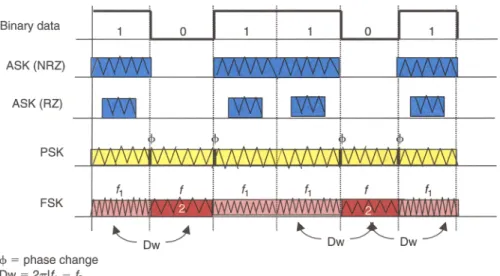
1.The implementation of FSK devices is based on electroacoustic Bragg mod-ulators or on distributed feedback (DFB) semiconductor lasers. Semiconductor lasers exhibit a frequency shift when the operating current changes. A small change in current (-1 rnA) would shift the frequency by -1 GHz. Because the current change is small, the intensity (amplitude) change is small,too.Thus, DFB semiconductor lasers make very good and fastcoherent FSK sources with high modulation efficiency. Figure 12.6 summarizes all the shift-keying modulation methods.
172 Part III Coding Optical Information Binary data
o
ASK (NRZ) ASK (RZ) PSK FSK <p= phase change Dw= 21Tlf1 - f2 ~ !~ DwFigure 12.6 Examples of coding/decodingoptical information.
EXERCISES
1. In optical coherentsystems, what type isthe local oscillator at the receiver? 2. Which parameter(s)may be modulated in digitaltransmission?
3. Consideran on-off modulator.How is thismodulationmethod classified? 4. Which modulation technique(s) would be bettersuited for long-haulapplications? 5. Mention two coherent modulation techniques .
6. What is the difference between an electricalRZsignal and an optical RZ signal? 7. Are bipolarsignals possible in optical transmission?
8. A signal iscoded usingan 8BIl OB coder.If the bit rate before the coder is 2 Gb/s, what is the bit rateon the fiber?