MultiCraft Vol. 3, No. 8, 2011, pp. 297-306
SCIENCE AND TECHNOLOGY
www.ijest-ng.com
©2011 MultiCraft Limited. All rights reserved
Development of a data acquisition and greenhouse control system
based on GSM
A. Rahali
1, M. Guerbaoui
1, A. Ed-dahhak
2*, Y. El Afou
1, A. Tannouche
2, A. Lachhab
2,
B. Bouchikhi
11
Laboratory of Electronics, Automatics and Biotechnology, Faculty of Sciences, Moulay Ismaïl University, Meknes, MOROCCO.
2Team Modeling, Systems Control and Telecommunications, High School of Technology, Moulay Ismaïl University, Meknes, MOROCCO. *Corresponding Author: e-mail: [email protected], Tel +212-5-35 46 70 84, Fax. +212-5-35 46 70 83
Abstract
This paper explains the design and implementation of electronic system based on GSM (Global System for Mobile communication) for controlling the climate parameters by SMS (Short Message Service) in greenhouse. The main purpose of this system conception is the remote control of the climatic parameters that influence the production in greenhouse (Temperature, relative humidity of air and soil moisture). Several sensors and actuators are installed and connected to a management and acquisition card. These sensors provide relevant information that is used to control ventilation, heating and pump by SMS. The procedure used in our system provides the owner with a remote control avoiding the needed to perform the control actions on site. The developed system in this paper is ideally suited for agricultural greenhouses in Morocco. It is simple to be installed and used by farmers who do not have knowledge in computer skills. Besides, most people use their cell phones to communicate and send messages. Thus, in our system, with a simple message, all farmers can control their greenhouses from a distance. They can know the status of their greenhouse climate at any time (temperature, humidity...) and can control actuators to adjust these parameters (fan, heater, vent, drip irrigation...). Thus, we have developed a graphical interface using LabVIEW software for the local acquisition, monitoring with PC and storage of all data through the card PCL812PG.
Keywords: Sensors, Greenhouse, Microcontroller, GSM, Control, Monitoring.
DOI: http://dx.doi.org/10.4314/ijest.v3i8.23
1. Introduction
The greenhouse industry is the fastest growing sector worldwide. The greenhouse separates the crop from the environment, thus providing some way of shelter from the direct influence of the external weather conditions (Tantau, 2003; Ruiz-Garcia, 2009). This enables the production of crops that otherwise could not be produced at that specific location. The greenhouse enclosure permits the manipulation of the crop environment. This asset allows the farmer to steer the cultivation in a desirable direction. It leads to higher crop yield, prolonged production period, better quality, and less use of protective chemicals. The added value per unit area in greenhouse crops is much higher than that in open-field cultivation. In moderate climate zones, energy is needed, whereas in arid zones, the cooling and availability of water is of major concern (Baille et al, 2001; El Fadl et al, 1996). The use of materials and energy as well as crop yield and quality can be influenced by operating the adjustable components of greenhouse, such as heating and cooling inputs, window opening, drip irrigation, screening and CO2 dosage. Hence, it can be expected that the way these controls are operated influences the final economic result (Campagne, 1997; Dussion, 1989; Choukr-allah, 1996; Urban, 1997). To fully exploit the enhanced possibilities for crop and resource management in greenhouse, it is indispensable to adjust and control variables with a remote automatic controlling system via SMS by using the GSM (Adedjouma et al, 2006; Hayat Khiyal et al, 2009; Ramamurthy, 2010). This is because it is almost difficult for human being to manipulate and be present every day near the system. Indeed, remote communication systems are a major component of the policy of modernization and technology
GSM, it comes immediately to mind: i) voice communication; ii) sending and receiving SMS/MMS; and iii) mobile internet. It is obvious to think that in using these services provided by this technology, it is possible to control and monitor systems from a distance using the GSM network (Li et al, 2010; Pawlowski et al, 2009; Romaguera, 2010). Mobile communications are integrated-applications as useful and current as home automation, industrial applications for handling and remote monitoring of complex systems but also in security systems, and protect property and people.
Most physical variables relevant in a greenhouse can be measured by automatic sensors. This holds for temperature, soil moisture, and relative humidity. The most important disturbance factors can be measured with sensors as well, that is, outside temperature, outside relative humidity, wind speed, and solar radiation. Precipitation can also be detected, although it is somewhat less common. All the mentioned physical variables are sampled and stored electronically at regular intervals when something is changing. Also, in principle, the control inputs are known, although it must be said that these important data are not always recorded. Overall, the measurements provide quite a good input-output picture of the physical part of the greenhouse crop system.
We propose a contribution to the development of greenhouse production in Morocco
.
This paper presents the design and development of an electronic system based on a microcontroller that integrates remote control functions rooted in the GSM network (Adedjouma et al, 2006). The system allows the acquisition of different climatic parameters in an agricultural greenhouse. In addition, this electronic system achieves the control and remote monitoring of greenhouse solutions, in particular drip irrigation stations, by sending SMS messages (Lajara et al, 2011; Luthra et al, 1997). The system, also, includes a serial cable, a GSM, conditional sensors card, power interfaces and microcontroller. An active SIM card is required to receive and send messages. We have developed a graphical user interface using LabVIEW software for the acquisition, monitoring with PC and storage of all data through the PCL812PG card. This interface encompasses at the same time reliability, flexibility of use, interactivity and processing capability in real-time of the whole data. Our systems present several advantages: i) user friendly; ii) easily implemented; iii) focus main parameters; iii) use GSM phones because of theirs availability; iv) low cost of SMS in Morocco; and v) network coverage (3 operators existing in Morocco cover all the territory).2. Functional Block Diagram and Description of the System
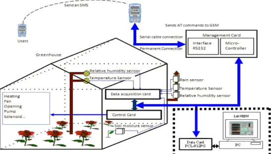
Figure 1 shows the functional block diagram of the entire system. All the major subsystem blocks are shown with their interconnections to each module. The block diagram consists of: i) data acquisition card to acquire the various climatic parameters; ii) control card of the actuators (heating, ventilation, opening, valve,..); iii) management card which contain MAX232 Level converter/inverter and microcontroller; iv) mobile phone (GSM) with integrated modem which enables the system to be remotely controlled and monitored over the whole coverage of the network used; and v) mobile user and personal computer (Benghanem, 2009). Authentication based on the contents of the commands (AT) is routinely performed to ensure safety while allowing the use of any phone. The remote functions are: i) opening / closing of the vent panels; ii) tripping / switching on the irrigation valve; and iii) turning on/ off the ventilation and heating. The SMS sent by the system to the user is in turn used to notify any detection or confirm the recognition of controls. All sensors and actuators are directly connected to the computer system through a data acquisition card PCL812PG (Eddahhak and al, 2007). A Graphical user interfaces (GUI), based on National Instruments LabVIEW 2009, was developed to acquire and monitor various climatic parameters inside and outside the greenhouse. The LabVIEW 2009 full edition license costs $2,699.
3. Hardware
The detailed descriptions of the blocks cards used in the greenhouse system are explained below.
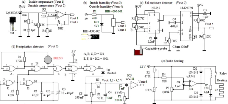
3.1 Measurements card: Figure 2 shows the circuit diagram of the developed entire measurement card. This card performs the
measurement or detection of climatic parameters inside and outside the greenhouse.
Figure 2. Electronics circuit of a measurement card. (a) Temperature sensor and associated circuit conditioner; (b) Relative
humidity sensor; (c) Electronic circuit of the soil moisture detector; (d, e) Precipitation detector and probe heating.
For temperature measurement, our choice was carried out on a sensor LM35DZ with a typical accuracy of 0.4°C at a temperature of 25 °C and a sensitivity of 10mV/°C. When using a long cable (shielded) to connect the sensor with the circuit, a filter R1C1 is connected between the sensor output and ground (R1 = 10 Ω and C1 = 1
μ
F). The conditioning circuit is composed by a filter followed by a no inverting amplifier. The equation of variation of the output voltage of the circuit as a function of temperature is from elated as follows:05
,
2
17
,
11
×
1−
=
V
outT
(1)With: T in degree centigrade and Vout1 in Volt.
The HIH-4000-001 humidity sensor is used to measure the relative humidity. The measuring range of this sensor is from 5% to 95 %. Using the calibration curve of this sensor, the following formula is used (Honeywell sensors):
)
16
,
0
(
62
10
supply 3 4−
=
V
V
RH
out (2)With: RH in %, Vout2 in Volt and Vsupply = 5 V.
Soil moisture can be detected by an electronic circuit based on a capacitive probe. The principle of this capacitive probe is thus based on the variation of the capacity via its permittivity. The circuit conditioner consists of an NE555 astable multivibrator followed by a LM2907N frequency-voltage converter (Vout5 = fIN x VCC x P2 x C4). It is sufficient to measure the output voltage of the circuit conditioner to estimate the amount of watering) (Bouchikhi et al, 2004). Depending on the ground hydrous state, a solenoid of the irrigation station is opened by SMS when the Vout5 voltage exceeds 4 V (dry soil) and is closed also by SMS when Vout5 reaches 2 V (wet soil).
The rain sensor used, IBR273 (lextronic), is based on the capacitive principle. The capacity of the sensitive element of the sensor depends on the wetted surface by drops of water (100 pF with humidity from 10 %). It’s the most appropriate sensor for this
purpose because it allows a fast response. Heated rain grids enable snow sensing and differentiation between dew and rain. The sensor is insensitive to humidity through a heating resistor of 42 Ω. A temperature sensor type NTC with a specific value of 1 kΩ
at 25 °C. The capacitive probe is associated with a variable frequency oscillator (NOR gates A and B). A second oscillator (NOR gates C and D) generates a square wave frequency 10 kHz and 50 % duty cycle. The combination of the two oscillators is designed to generate a modulated signal of the pulse width formed by NOR gates E, F and G. It converts the variable frequency voltage (C3, R3, C4 and P1). We used a comparator to obtain a logical signal (0 V: raining, 5 V: absence of precipitation) whose threshold is adjustable by the potentiometer P2. This device is mounted on the outdoor weather stations to detect precipitation. Simple rain “grids” indicate either the presence or absence of precipitation but not the volume. This simple sensor is commonly used to close or limit roof vents or retractable roofs when it is raining. The developed precipitation detector is able to inform the microcontroller after receiving a few drops on his sensing face.
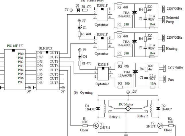
3.2 Control card: The electronic circuit of the control card is shown in Figure 3. It’s developed for controlling greenhouse equipment (solenoid, pump, heating, fan and DC motor). The outputs of the PIC16F877 control of static relays based on triac TBA16A/600B through the integrated circuit ULN2803. The ULN2803A contain eight darlington transistors with common emitters and integral suppression diodes for inductive loads. The K3021P consists of a phototriac optically coupled to a gallium arsenide infrared-emitting diode in a 6-lead plastic dual inline package. The k3021 provides galvanic isolation between the ULN2803 and the triac. The LED D1 displays the state of output signals of the microcontroller. Figure 3.b shows the electronic
interface for controlling a DC motor ensuring the opening and closing of the roof. The reversal of motor rotation is provided by two relays and two switching transistors 2N1711.
Figure 3. Electronic circuits of the control card; (a) Static relay; (b) Electronic interface for a DC motor.
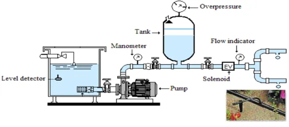
3.3 Drip irrigation station: The drip irrigation station (Figure 4) includes an electric pump, a system of filtration, a flow indicator,
a bladder tank, a governor with automatically-controlled valves, a solenoid and a drain pipes. The pumping station is used to pump water from a well into a tank. The pump is selected according to the requirements in liters per minute and the pressure required to pipes. The operation of the pump is dependent on the water level in the tank. The overpressure will ensure adequate pressure for the distribution of water in the pipes. The manometer measures the water pressure in the irrigation system.
The drip irrigation station is installed at the Faculty of Sciences (Meknes, Morocco). A typical application is a remote pump that is commonly used by water supply and irrigation systems. Via SMS irrigation control, using SMS text instruction can be stopped, started or run pump and solenoids, (Dae-Heon et al, 2011; Jiang et al, 2009; Ozdogan et al, 2010).
Figure 4. Drip irrigation station.
3.4 Management card: The management card is shown in Figure 5. The data collected by the PIC16F877 microcontroller are
transmitted to a GSM with an RS232 serial interface. Since the RS232 is not compatible with today’s Microcontrollers, we need a line drive or voltage converter to convert RS232 signals to TTL voltage levels. One example of such a converter is MAX232 from Maxim corp. The MAX232 converter converts RS232 voltage levels to TTL voltage levels and vice versa. One advantage of the MAX232 chip is that it uses a +5 V power source, which is the same as the source voltage for the microcontroller. In other words with a single +5 V power supply we can power both the MAX232 and microcontroller, with no need for the dual power supplies that are common in many older systems. The MAX232 has two sets of line drivers for transferring and receiving data. In the proposed system we have used a standard GSM mobile phone with integrated modem and the appropriate cable to connect to a serial interface on PIC. Any phone that supports the "extended AT command set" for sending/receiving SMS messages, as defined in the ETSI GSM 07.05 specification can be supported by the Now SMS/MMS Gateway.
Figure 5. Management card.
3.5 Multi-function card PCL812PG: Its main features are 16 single-ended analog input channels with 12 bits resolution, 16 digit
I/O channels, 2 analog output channels and an Intel programmable timer/counter (Advantech, 1994). Some other experimental sensors and actuators are directly connected to the computer system through a PCL812PG.We have collected data from different sensors installed both inside and outside the greenhouse.
4. Software
4.1 Implementation of the remote control and communication by SMS: Some simple command <<AT>> line programs to access a
GSM mobile phone via GSM modem. Reading, writing, sending and receiving SMS messages using the GSM standards ETSI GSM 07.07, ETSI GSM 07.05, and others. The communication between the microcontroller and the GSM terminal integrated in the system is realized through an asynchronous serial link RS232 (Adedjouma and al, 2006; Benghanem, 2009). The command AT + CNMI = 1, 1 configures the GSM module to a microcontroller systematic indication of the arrival of a new text by the response frame <CR> <LF> + CMTI: <mem>, <index> <CR> <LF>. The SMS is <<read>> with the command AT + CMGR = <index> <CR>, to which the terminal responds with: <CR><LF>+CMGR: "REC READ", "sender number", "AA/MM/JJ, hh:mm:ss±zz"<CR><LF>message body <CR> <LF> <CR> <LF>OK<CR><LF>. (zz =time zone).
yes
We just need to extract from the entire received frame, useful information to our application. The identification of the instruction received by SMS precedes a test of character mapping of the message.
4.2 The flowchart for remote control process: Figure 6 illustrates the flowchart of the global remote control process. The
management card is made to two tasks that are essential to command and remote control via GSM network. For this, two controls were developed following a very specific syntax in order to distinguished from the usual content of a message can be received by the GSM. This reduces the risk of unsafe operation after receiving an SMS undesirable "spam", such as SMS publicity.
Figure 6. The flowchart for remote control process.
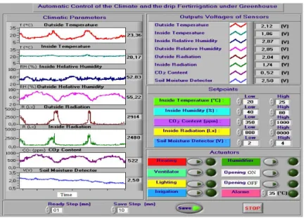
4.3 Virtual Instrument: In this section, the user is able to locally monitor the plant in a very user friendly manner where details are
represented in dynamic graphical interfaces in personal computer. We have developed a Virtual Instrument (VI), using labVIEW software, regrouping the following functionalities (Eddahhak, 2009): i) acquirement and data logging; ii) display and treatment of information in real-time; and iii) command of actuators. The dashboard of this VI is shown in Figure 7. The driving software enables us to fix two temperature thresholds, in our example and according to climatic needs of the plants, we chose as temperature thresholds: Tlow = 20°C and Thigh = 25°C. Consequently, the heating system engages when the temperature becomes lower than 20°C. On the other hand, the ventilation system starts to function operate when the temperature goes higher than 25°C. The climatic parameters were measured every minute and stored every 10 minutes. All data were collected in a greenhouse between 22-26 November 2010.
No
Start Initialize PIC16F877 microcontroller Initialize ADC and Serial port of microcontroller
-Enter the number of messaging on the mobile phone operator chosen
-Set the maximum validity period of SMS -Define the type of message text
Clear the output ports
Read the input signal from sensors Start A/D conversion
Load the values in the registers
GSM sends signal to the microcontroller through UART
Message is decoded in the microcontroller
If the decoded message is a proper device control
command?
SMS is shot back to user mobile phone constraining the status in the requested forms
Device switching ON/OFF actions is performed
GSM sends an acknowledgment to the user
END If user sends SMS to GSM? Yes No Yes
Figure 7: The dashboard of the virtual instrument. 5. Results and Discussions
5.1 Remote control system with SMS text message: the Table 1 summarizes the results of remote control system with SMS text
message notification direct to mobile phone.
Table 1: Monitoring and remote control system with SMS text message
SMS command Acknowledgment Comments
State of input-output #*****#
Tin=26.5’°C’, Tout=28’°C’ Hin=50’%’ , Hout=60’%’ Hsoil=1.23’v’, Rain=0; Irri=0, Heat=0, Fan=0, Open=0, Close=0
Analogue inputs: Tin: Inside temperature Tout: Outside temperature Hin: Inside Humidity Hout: Outside Humidity Hsoil: Soil moisture
Digital inputs: Rain: Rain detector Digital outputs:
Irri: Command drip irrigation (Irri=0 OFF, Irri=1 ON)
Heat: Command heater Fan: Command fan
Open: Command the opening of the roof Close: Command the closing of the roof Start irrigation #10000#
Tin=26.5’°C’, Tout=28’°C’ Hin=50’%’ , Hout=60’%’ Hsoil=1.23’v’, Rain=0; Irri=1, Heat=0, Fan=0, Open=0, Close=0
To start the irrigation, the command: #1000# is sent via SMS to mobile phone number linked to the management card.
The system confirms the execution of this command by sending an acknowledgment.
Stop irrigation #00000#
Tin=24.5’°C’, Tout=28’°C’ Hin=55’%’ , Hout=60’%’ Hsoil=2.23’v’, Rain=0; Irri=0, Heat=0, Fan=0, Open=0, Close=0
The system replies by sending another acknowledgment to the sender to confirm the execution of the new command.
Start Fan and
close the roof #00101#
Tin=24.5’°C’, Tout=28’°C’ Hin=55’%’ , Hout=60’%’ Hsoil=2.23’v’, Rain=0; Irri=0, Heat=0, Fan=1, Open=0, Close=1
It is noted on the acknowledgment received confirmation of the start of fan and close the roof by switching to "1" the outputs “Fan” and “Close”.
We may, at any time, query the system to know the current status of its inputs and outputs or to find the temperature, humidity ... and those without affecting the output status by sending the following command: #****#.
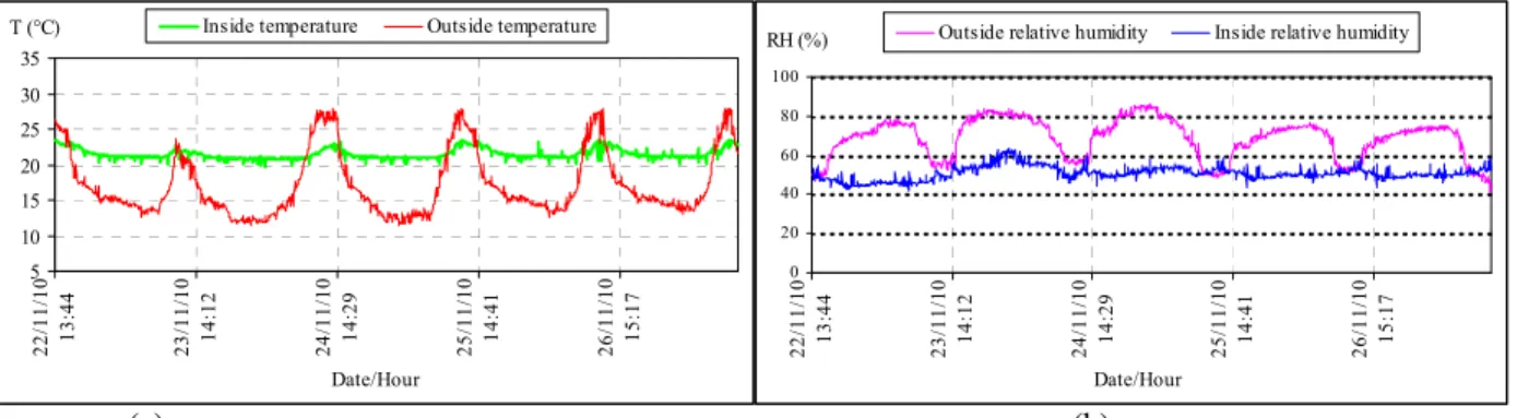
5.2 Local control. We present the evolution of the external temperature and the controlled internal temperature in Figure 8(a). The
value of the outside temperature is in the interval [12 °C, 27 °C]. We note that the temperature under greenhouse is maintained in the desired range (21 °C at night and 23 °C in the day). Moreover, we notice that the evolution of internal temperature is influenced by the evolution of external temperature. Indeed, these two parameters display their minimum and maximum values at the same moments of the day. The experimental result shows that the optimum of the internal temperature for the photosynthesis can be maintained constant for a relatively long time.
We can make the same remarks with regard to the evolution of external humidity (Figure 8 (b)), which varies within the range of [50 %, 85 %]. It can be seen that the relative humidity under greenhouse is influenced by the inside temperature and varies in the interval of [45 %, 62 %] (Eddahhak et al, 2007; El Harzli, 2009).
5 10 15 20 25 30 35 22 /11/ 10 13 :4 4 23 /11/ 10 14 :1 2 24 /11/ 10 14 :2 9 25 /11/ 10 14 :4 1 26 /11/ 10 15 :1 7 Date/Hour
T (°C) Inside temperature Outside temperature
0 20 40 60 80 100 22 /11/ 10 13 :4 4 23 /11/ 10 14 :1 2 24 /11/ 10 14 :2 9 25 /11/ 10 14 :4 1 26 /11/ 10 15 :1 7 Date/Hour
RH (%) Outside relative humidity Inside relative humidity
(a) (b)
Figure 8: Temperature and relative humidity curves. 6. Conclusion
The system is designed for controlling and monitoring any remote equipment in greenhouse by a simple SMS from anywhere in the world via the GSM network. The developed system can be a very profitable investment because it will be able to optimize the use of the resources used in greenhouse. The GSM network operating in the design of this system has allowed us to make our greenhouse more autonomous and, thus, to adapt it to the constraints and Moroccan socio-economic realities that do not necessarily match with the technological and economic development of Western countries that are real consumer societies. Our work has consisted mainly of optimizing simple ways (using SMS) to realize real tools for remote monitoring of climate parameters and of drip irrigation in greenhouses in Morocco by strengthening the capacity and coverage action of farmers who are often uneducated. Using this system and with a simple SMS, we can start and stop different actuators as well as know the climate under greenhouse via the GSM network from anywhere. In addition, the project is essentially a multidisciplinary educational support as well as part of a student training and research.
Acknowledgements
This work was supported by the “Centre National de Coordination et de Planification de la Recherche Scientifique et Technique” (CNCPRST) under project PROTAS III n°D43/07 and by the “Moulay Ismaïl University ” under project: “Appui à la recherche”. References
Adedjouma A.S., Adjovi G., Agaï L. and Degbo B., 2006. A system of remote control car lock with a GSM based geo-location by GPS and GSM.African Journal of Research in Computer Science and Applied Mathematics, Vol. 1, pp. 1-8.
Advantech Co., 1994. PC-LabCard Software Driver User’s Manual for PCL-812PG.
Baille A., Kittas C. et Katsoulas N., 2001. Influence of whitening on greenhouse microclimate and crop energy partitioning. Journal of Agricultural and Forest Meteorology, Vol. 107, pp. 293-306.
Benghanem M., 2009. Measurement of meteorological data based on wireless data acquisition system monitoring. Journal of
Applied Energy, Vol. 86, pp. 2651-2660.
Bouchikhi B., Eddahhak A., El Harzli M. et El Bari N., 2004. The sensors and their role in the measurement of climatic parameters for the management of irrigation water in greenhouse agriculture. International days of Science and Technologies, Cadiz,Tangier
Bouchikhi B., El Harzli M., 2005. Design and realization of acquisition system and climatic parameters control under the greenhouse. Phys & Chem. News, Vol. 22, pp. 45-54.
Campagne P., 1997. The modernization of agriculture: some economic issues. Bourakis G. (ed.). Notebooks Options Mediterranean, Vol. 29, pp. 47-56.
Choukr-allah R., 1996. “Protected culture in Morocco”.
Choukr-Allah R. (ed.).
Protected cultivation in the Mediterranean region. Notebooks Options Mediterranean, Vol. 31, pp.9-15.Dae-Heon P. and Jang-Woo P., 2011. Wireless sensor network-based greenhouse environment monitoring and automatic control system for dew condensation prevention. Journal of Sensors, Vol. 11, pp. 3640-3651.
Dussion M. F., 1989. Greenhouse and energy. French Agency for Energy Management, p. 96.
Eddahhak A., 2009. Development of a system for monitoring the climate and managing the drip fertilizing irrigation in greenhouse by using LabVIEW software. National PhD, Faculty of Sciences, Meknes, Moulay Ismail University, Morocco
Eddahhak A., Lachhab A., Ezzine L. and Bouchikhi B., 2007. Performance evaluation of a developing greenhouse climate control with a computer system. AMSE Journal Modelling C, Vol. 68, No. 1, pp. 53-64.
El-Fadl A., El Kherrak H., Claustriaux J. et Mounhim H., 1996. Computer aided management of greenhouse climate and influence on the culture of melon in the region of Souss. Choukr-Allah R. (ed.). Protected cultivation in the Mediterranean region. Notebooks Options Mediterranean Vol. 31, pp. 99-108.
El Harzli M., 2009. Study and realization of a multifunctional sensor, heat flux, temperature and humidity. Application to the greenhouse control. National PhD , Faculty of Sciences, Meknes, Moulay Ismail University, Morocco
Hayat Khiyal M. S., Khan A. and Shehzadi E., 2009. SMS Based Wireless Home Appliance Control System (HACS) for Automating Appliances and Security. Issues in Informing Science and Information Technology, Vol. 6, pp. 887-894.
Jiang P., Xia H., Zhiye He Z. and Wang Z., 2009. Design of a water Environment monitoring system based on wireless sensor networks. Journal of Sensors Vol. 9, pp. 6411-6434.
Lajara R., Alberola J. and Pelegrí-Sebastiá J., 2011. A Solar Energy Powered Autonomous Wireless Actuator Node for Irrigation Systems. Journal of Sensors. Vol. 11, pp. 329-340.
Li X. H., Cheng X., Yan K. and Gong P., 2010. A monitoring system for vegetable greenhouses based on a wireless sensor network. Journal of Sensors, Vol. 10, pp. 8963-8980.
Luthra S. K., Kaledhonkar M. J., Singh O. P. et Tyagi N. K., 1997. Design and development of an auto irrigation system Agricultural Water Management, Vol. 33, pp. 169-181.
Oguic P., 2000. Measures and PC, ETSF, 2nd edition, Dunod, pp. 254.
Ozdogan M., Yang Y., Allez G. and Cervantes C., 2010. Remote sensing of irrigated agriculture: Opportunities and challenges. Journal of Remote Sensing, Vol. 2, pp. 2274-2304.
Pawlowski A., Guzman J. L., Rodríguez F., Berenguel M., Sánchez J. and Dormido S, 2009. Simulation of greenhouse climate monitoring and control with wireless sensor network and event-based control. Journal of Sensors, Vol. 9, pp. 232-252.
Ramamurthy B., Bhargavi S., ShashiKumar R., 2010. Development of a low-cost GSM SMS-based humidity remote monitoring and control system for industrial applications. International Journal of Advanced Computer Science and Applications
(IJACSA), Vol. 1, No. 4.
Romaguera M., Hoekstra A. Y., Su Z., Maarten S. K. and Suhyb Salama M., 2010. Potential of using remote sensing techniques for global assessment of water footprint of crops. Journal of Remote Sensing, Vol. 2, pp. 1177-1196.
Ruiz-Garcia L., Lunadei L., Barreiro P. and Ignacio Robla J., 2009. A Review of Wireless Sensor Technologies and Applications in Agriculture and Food Industry: State of the Art and Current Trends. Journal of Sensors, Vol. 9, pp. 4728-4750.
Tantau H.J. and Lange D., 2003. Greenhouse climate control: an approach for integrated pest management. Computers and
Electronics in Agriculture, Vol.40, pp. 141-152.
Urban L., 1997. Introduction to greenhouse production. Management of the climate. Lavoisier Publishing, Technology & Documentation, Vol 1, p. 306.
Urban L., 1997. Introduction to greenhouse production. The fertigation in soilless culture Lavoisier Publishing, Technology & Documentation, Vol 2, p. 210.
Biographical notes
A. Rahali is a Professor in the Department of Physics, Faculty of Sciences, Moulay Ismaïl University, Meknes, Morocco. Member of Laboratory of Electronics, Automatics and Biotechnology. His research interests include industrial process control.
M. Guerbaoui is a teacher at High School in Engineering Science since 1996, and currently a PhD student at the Electronics Automatic and Biotechnology
Laboratory, Moulay Ismaïl University, Faculty of Sciences in Meknes, Morocco. His research interests include regulating parameters under greenhouse by Fuzzy logic and use of solar energy equipment in the greenhouse.
A. Ed-dahhak received Ph.D from Faculty of Sciences Meknes in 2009. He is a Professor in the Department of Electrical Engineering, High School of Technology Meknes, Moulay Ismaïl University, Morocco. Abdelali Ed-dahhak is a member of Laboratory of Electronics, Automatics and Biotechnology of the Faculty of Sciences, Meknes. His current area of research includes electronics, development of a system for monitoring the climate and managing the drip fertilizing irrigation in greenhouse.
Y. EL Afou is currently a Ph.D student at the Electronics Automatic and Biotechnology Laboratory, University Moulay Ismaïl, Faculty of Sciences of Meknes, Morocco and Automatic informatics engineering and Signal laboratory, University of Sciences and Technology of Lille1. His research interests include regulating parameters under greenhouse by control free model.
A.Tannouche is currently a PhD student at the Electronics Automatic and Biotechnology Laboratory, Moulay Ismaïl University, Faculty of Sciences in Meknes,
Morocco. His research interests include conception and implementation of a bio-inspired vision system
A. Lachhab received Ph.D from Faculty of Sciences in Rabat in 2000. He is a Professor in the Department of Electrical Engineering, High School of Technology Meknes, Moulay Ismaïl University, Morocco. Member of Laboratory of Electronics, Automatics and Biotechnology in Faculty of Sciences in Meknes.. His current area of research includes Automatic.
B. Bouchikhi received the Ph.D. degree from the Université de droit, d’Economie et des Sciences d’Aix Marseille III, in 1982. Benachir Bouchikhi was awarded a Doctor of Sciences degree in 1988 from the University of Nancy I. Dr. Bouchikhi got a position of titular professor at the University of Moulay Ismaïl, Faculty of Sciences in Meknes, Morocco since 1993. He is the director of the Laboratory of Electronics, Automatic and Biotechnology. His current research interests involve metal oxide sensors for electronic noses and their application to food analysis and the control of the climate and drip fertirrigation under greenhouse. He is author and co-author of over 42 papers, published on international journals. During the last 10 years he has coordinated a dozen national and international projects, in the area of food safety, the control of the climate and drip fertirrigation under greenhouse. He is a member of the Editorial Board of Journal of Sensors.
Received October 2011 Accepted May 2012