Contents
1 Rendering Reference 6 1.1 Render Type . . . 6 1.2 Sampling . . . 7 1.2.1 Anti-Aliasing . . . 7 1.2.2 Prepass . . . 8 1.2.3 Ray Tracing . . . 8 1.3 Global Illumination . . . 9 1.3.1 Color Balance . . . 10 1.3.2 Final Gather . . . 12 1.3.3 Path Tracer . . . 17 1.3.4 Monte Carlo . . . 201.3.5 Global Photon Map . . . 21
1.3.6 Dynamic Photon Map . . . 23
1.3.7 Caustics Photon Map . . . 25
1.3.8 Advanced Settings . . . 26
1.4 Environment . . . 27
1.4.1 Sky Light . . . 28
1.4.2 Image Based Lighting (IBL) . . . 28
1.5 Options . . . 31
1.5.1 Memory and Performance . . . 31
1.5.2 Frame Buffer . . . 34
1.5.3 Overrides . . . 36
1.5.4 Output Verbosity . . . 38
1.6 Turtle settings on Maya nodes . . . 39
1.7 Geometry Object Settings . . . 39
1.7.1 Subdivision Settings . . . 39
1.7.2 Renderstats . . . 40
1.7.3 Global Illumination Settings . . . 42
1.7.4 Bake Resolution Override . . . 43
1.8 Light Settings . . . 43
1.8.1 Intensity Settings . . . 43
1.8.2 Decay Settings . . . 45
1.8.3 Shadow Settings . . . 45
1.8.4 Global Illumination Settings . . . 47
1.8.5 IES Settings . . . 47
1.9 Camera Settings . . . 47
1.10 Material Settings . . . 48
1.10.2 Global Illumination . . . 50
1.11 Displacement Mapping . . . 51
1.11.1 Common Displacement Settings . . . 51
1.11.2 Rendertime Micro Triangles . . . 51
1.11.3 Pre-Tesselation . . . 53
1.11.4 Displacement Bounds . . . 54
1.12 File Texture Settings . . . 55
1.13 Shading Engine Settings . . . 55
1.14 Render Layer Settings . . . 57
1.15 Nurbs Tessellation . . . 57
1.16 IBL Light Rig Editor . . . 57
1.16.1 IBL Light Rig Editor Options . . . 57
1.17 Programmable Shading . . . 59
1.17.1 The Lua Node . . . 60
1.17.2 Turtle extensions to Lua . . . 60
1.17.3 A note on using the Lua node as an Output Shader . . . 62
1.17.4 Examples on Lua shaders . . . 63
2 Baking Reference 66 2.1 Bake Layers . . . 66
2.1.1 Bake Layer Editor . . . 68
2.2 Bake Layer Settings . . . 70
2.2.1 Targets . . . 70
2.2.2 Common Settings . . . 74
2.2.3 Texture Bake Settings . . . 74
2.2.4 Vertex Bake Settings . . . 78
2.2.5 Outputs . . . 82
2.3 Advanced Baking . . . 84
2.3.1 Radiosity Normal Maps . . . 84
2.3.2 Directional Occlusion . . . 85
2.3.3 Polynomial Texture Maps . . . 85
2.3.4 Spherical Harmonics . . . 86
2.4 Programmable Baking . . . 86
2.4.1 The Lua bake script . . . 86
2.4.2 Setup function . . . 86
2.4.3 Basis function . . . 88
2.4.4 Bake function . . . 89
2.4.5 Using the Radiance Cache with Lua . . . 90
2.5 Point Cloud Baking . . . 90
2.5.1 Create Dough Point Cloud . . . 91
2.5.2 Bake Point Cloud . . . 91
2.5.3 Point cloud files . . . 92
2.6 Texture Resampling . . . 92
3 Batch Rendering Reference 95 3.1 Command Line Frame Rendering . . . 95
4 Turtle Nodes Reference 101
4.1 Surface Shader Nodes . . . 101
4.1.1 ilrOccSampler . . . 101
4.1.2 ilrBssrdfShader, Subsurface Scattering . . . 105
4.1.3 ilrOrenNayar Shader . . . 107
4.1.4 ilrAshikiminShader . . . 109
4.1.5 ilrDielectricShader . . . 112
4.2 Photon Shader Nodes . . . 113
4.2.1 ilrBasicPhotonShader . . . 113 4.2.2 ilrPhysicPhotonShader . . . 114 4.2.3 ilrDielectricPhotonShader . . . 115 4.3 Utility Nodes . . . 115 4.3.1 ilrOutputShaderBackendNode . . . 115 4.3.2 ilrUVMappingVisualizer . . . 115 4.3.3 ilrOccData . . . 117 4.3.4 ilrRaySampler . . . 118 4.3.5 ilrNormalMap . . . 121 4.3.6 ilrSurfaceThickness . . . 122 4.3.7 ilrShadowMask . . . 123 4.3.8 ilrLuaNode . . . 124 4.3.9 ilrHwBakeVisualizer . . . 124 4.3.10 ilrPolyColorPerVertex . . . 126 4.4 Geometry Nodes . . . 126 4.4.1 ilrPointCloudShape . . . 126
5 Turtle Commands Reference 129 5.1 Render Commands . . . 129 5.1.1 ilrRenderCmd . . . 129 5.1.2 ilrBatchRenderCmd . . . 129 5.2 Bake Commands . . . 130 5.2.1 ilrTextureBakeCmd . . . 130 5.2.2 ilrVertexBakeCmd . . . 131 5.2.3 ilrImportVertexColorsCmd . . . 132 5.2.4 ilrPointCloudCmd . . . 133 5.2.5 ilrUVSACmd . . . 134 5.2.6 ilrCreateSharedUVCmd . . . 134 5.3 Other Commands . . . 134 5.3.1 ilrDisplacementToPolyCmd . . . 134 5.3.2 ilrIBLCmd . . . 134 5.3.3 ilrGetFileLayersCmd . . . 135 6 Turtle Administration 136 6.1 Removing Turtle dependencies from a scene . . . 136
7 Appendix A: Copyrights 137 7.1 OpenEXR . . . 137
7.2 The Radiance Software License, Version 1.0 . . . 138
7.3 libJPEG . . . 139
7.4 libtiff . . . 140
7.6 libXML 2 . . . 141
7.7 libpng . . . 142
7.8 zlib . . . 143
7.9 GLFW . . . 144
c
2011 Autodesk, Inc. All rights reserved.
Chapter 1
Rendering Reference
All global render settings in Turtle can be found in Maya’s Render Settings window when Turtle is set as the current renderer. Common render settings, e.g for animation and image output, are located under theCommontab. Turtle specific settings can be found under the
Turtletab. The first control to set is the Render Type, which controls what type of rendering Turtle should do. Then there are five different categories of settings; Sampling, Global Illumination,Environment,OptionsandBaking.
Figure 1.1: Render Settings Window
1.1
Render Type
With theRender Typecontrol you select what type of rendering Turtle should do when a rendering is started in Maya. IfRenderingis selected Turtle will do ordinary frame render-ings from the current camera. A batch rendering in this mode will render all frames from
all renderable cameras according to the current animation settings. IfBakingis selected Turtle will instead perform baking to texture maps or vertex colors. The current bake layer controls which objects and what type of lighting/shading to bake. A batch rendering in this mode will bake out all bake layers that is set to renderable. For more information on baking, see section 2.
1.2
Sampling
The Sampling tab holds controls for Anti-Aliasing as well as controls for Ray Tracing.
1.2.1
Anti-Aliasing
Min/Max Sample Rate
Turtle uses an adaptive sampling scheme that can perform both undersampling (less than one sample per pixel) and oversampling (multiple samples per pixel). A sampling rate from one sample per 256 pixels and up to 256 samples per pixel can be used. The minimum and maximum sample rate Turtle should use. The min to max number of samples taken are printed in text in the GUI.
Contrast threshold
If the contrast differs less than this threshold Turtle will consider the sampling good enough. Diagnose Sample Rate
Enable this to diagnose the density of the sampling. The brighter a pixel is, the more samples were taken at that position.
Clamp Values
To work efficiently, the sampling algorithm can clamp the intensity of the image to the [0..1] range. When rendering to OpenEXR this is not desired. Clamp values should then be unchecked.
Filter Type
The available filter kernels are: • Box • Triangle • Cubic • Gauss • Catmull-Rom • Lanczos • Mitchell
Filter Width
The width of the filter kernel in pixels. Range from 1.0 to 3.0. Filter Height
The height of the filter kernel in pixels. Range from 1.0 to 3.0.
1.2.2
Prepass
Sets the sample rate used during the GI precalculation pass. The prepass is progressive, rendering from a low resolution up to a high resolution in multiple passes.
Min/Max Sample Rate
TheMin Sample Rate sets the initial resolution, where a negative value means a lower resolution than the original image (in powers of two), e.g. -4 gives the original resolution divided by 16. TheMax Sample Ratesets the resolution of the final prepass, e.g 0 giving the same resolution as the original resolution. These controls should normally be left at default values -4/0, however by decreasing them you can render very fast GI preview renderings.
1.2.3
Ray Tracing
Figure 1.2 shows theRay Tracinginterface in the Maya Render Settings window.
Figure 1.2: Ray tracing settings
Max Ray Depth
The maximum number of ”bounces” a ray can take before being truncated. A bounce can be a reflection or refraction.
Reflections
The maximum number of reflections a ray can take before being truncated. This limits the value set in each material.
Refractions
The maximum number of refractions a ray can take before being truncated. This limits the value set in each material.
Shadows
Controls at what depth a ray can spawn shadow rays. If set to 1, only primary rays will spawn shadow rays. If set to 2, the first bounce will spawn shadow rays as well. This limits the value set in each material.
GI Transparency
The maximum number of transparent surfaces a GI ray can go through, before being trun-cated. This is used by all gathering light integrators, e.g. Final Gather, Monte Carlo, Occlu-sion and LUA samplings.
Bias
An error threshold to avoid self intersections. For example, a shadow ray should not inter-sect the same triangle as the primary ray did, but because of limited numerical precision, this can happen. The bias value moves the intersection point to eliminate this problem. If set to zero this value is computed automatically depending on the scene size.
1.3
Global Illumination
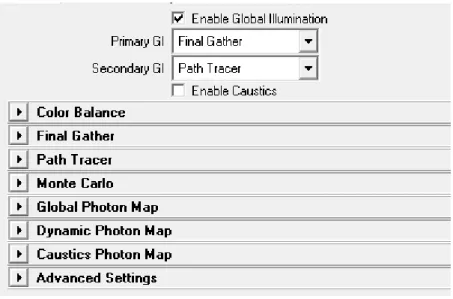
All settings for the global illumination algorithms are found under the Global Illumination tab. This is where you find caustics, photon map, path tracer, final gather and monte carlo settings. Figure 1.3 shows theGlobal Illuminationinterface in the Maya Render Settings window. TheEnable GIandEnable Causticsswitches are master controls for enabling the Global Illumination or Caustics.
Primary and Secondary GI
The Global Illumination system allows you to use two separate algorithms to calculate in-direct lighting. You can for instance calculate multiple light bounces with a fast algorithm like thePath Tracer, and still calculate the final bounce withFinal Gatherto get a fast high-quality global illumination render. Both subsystems have individual control ofIntensity
andSaturationto boost the effects if necessary. Available algorithms include • Photon Map
• Dynamic Photon Map(for advanced baking) • Path Tracer
• Final Gather
Figure 1.3: Global Illumination settings
There is also the option to useNoneboth as primary and secondary GI. For secondary GI, useNonewhen you don’t need deeper indirect light or if you have a primary GI that cannot use secondary GI. UsingNonefor primary GI should be done when baking advanced passes that perform their own gather, e.g. RNM (when not using radiance cache) and the Lua pass. When these passes perform their own gather, only the secondary GI will be sampled, making any primary GI useless.
Caustics
Enables caustics, using caustics photon mapping.
1.3.1
Color Balance
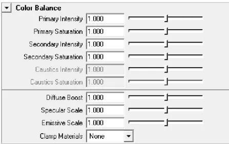
Figure 1.4 shows theColor Balanceinterface for GI.
Primary Intensity
Scales the intensity of the first GI bounce. Primary Saturation
Scales the saturation of the first GI bounce. Secondary Intensity
Scales the intensity of secondary GI bounces. Secondary Saturation
Figure 1.4: Color Balance Settings
Caustics Intensity
Scales the intensity of the caustics photon map. Caustics Saturation
Scales the saturation of the caustics photon map. Diffuse Boost
A gain for boosting the diffuse material components when used by GI. Can be used to adjust the amount of indirect diffuse lighting. For example, a scene with very dark textures will not get much indirect lighting, but when boosting all diffuse components the indirect effects are increased.
Specular Scale
Scales the specular material components when used by GI. Can be used to adjust the amount of indirect lighting from specular effects.
Emissive Scale
Scales the emissive material components when used by GI. Can be used to adjust the amount of indirect lighting from emissive materials.
Clamp Materials
Controls if materials should be clamped to preserve physical correctness when used by GI. • None: Disables material clamping.
• Intensity: Clamp the intensity (HSV Value).
1.3.2
Final Gather
Figure 1.5 shows theFinal Gatherinterface in the Maya Render Settings window.
Use Cache
Selects what caching method to use for final gathering.
• Off (Brute Force): disables caching and performs a new final gathering for every shad-ing point. Gives very accurate results but long render times. Can e.g. be used for reference images.
• Irradiance: caches the irradiance at selected points in the scene and uses interpolation in between the points. This is the default method.
• Radiance SH: caches radiance SH functions at selected points in the scene and uses in-terpolation in between the points. The radiance cache is useful in some advanced bak-ing passes (e.g. Radiosity Normal Maps), when directional indirect lightbak-ing is needed. Rays
Sets the maximum number of rays to use for each final gather sample point. A higher number gives higher quality, but longer rendering time.
Depth
Sets the number of indirect light bounces calculated by final gather. A value higher than 1 will produce more global illumination effects, but note that it can be quite slow since the number of rays will increase exponentially with the depth. It’s often better to use a fast method for secondary GI. If a secondary GI is used the number of set final gather bounces will be calculated first, before the secondary GI is called. So in most cases the depth should be set to 1 if a secondary GI is used.
Contrast Threshold
Controls how sensitive the final gather should be for contrast differences between the points during precalculation. If the contrast difference is above this threshold for neighbouring points, more points will be created in that area. This tells the algorithm to place points where they are really needed, e.g. at shadow boundaries or in areas where the indirect light changes quickly. Hence this threshold controls the number of points created in the scene adaptively. Note that if a low number of final gather rays are used, the points will have high variance and hence a high contrast difference, so in that case you might need to increase the contrast threshold to prevent points from clumping together.
Interpolation Points
Sets the number of final gather points to interpolate between. A higher value will give a smoother result, but can also smooth out details. If light leakage is introduced through walls when this value is increased, checking the sample visibility solves that problem, see Check Sample Visibility below.
Preview Calculation Pass
Turn this on to visualize the final gather prepass. Using the Preview Calculation Pass en-ables a quick preview of the final image lighting, reducing lighting setup time.
Use FG Map File
Controls usage of final gather map files. By saving the solution to a file, it can be reused for successive renderings. The file will be placed underturtle/fgMapsin the current project directory. Note that if lights or geometry are moved, recalculation is necessary.
• Off: Disables file usage.
• Overwrite: Creates a new map file, overwriting any existing file. • Reuse: Loads the map from a previously created file.
• Reuse and append: Loads the map from a file, but also writes back any new samples created during rendering.
• Precalc. for animation: Same as Reause and append, but only the FG pre-pass is rendered. This can be used to generate an FG Map file for an animation sequence. First render the animation in this mode, creating the map file, then switch to Reuse before final rendering of the animation. Note that the animation frame step can be set higher than 1 during the precalculation to save time. For instance rendering every other frame, or even as sparse as every 10th frame.
Note that different cache methods (Irradiance / Radiance SH) cannot share the same map file. To solve this problem irradiance cache files will be appended with ”.irradiance”. If Radiance SH is used with a depth higher than 1, irradiance caching is used for all sec-ondary bounces. So in that case two files will be saved, one Radiance SH cache file named “filename” and one Irradiance cache file named “filename.irradiance”.
File Name
Sets the file name of the final gather map file. Visualize in Model View
Visualize the stored samples as a point cloud in the Maya viewport. You can change point size and color in the attributes of the generated point cloud.
Use Legacy Settings
Enables the older final gather method. With this method points are placed according to the geometry in the scene. More samples are placed near walls and corners of the geometry. The contrast difference of the samples are not considered.
Accuracy (legacy)
Controls the sample point density. Higher accuracy generates more points and a better result at the expense of longer rendering time.
Smooth (legacy)
Applies a filter that reduces noise in the final gather solution. This is much faster than increasing accuracy or sending more rays. 1.0 is the default value. Values below 1.0 gives a sharper and noisier look, values above 1.0 gives a smoother look with less details preserved. Disable Min Radius (legacy)
When enabled more points will be created in corners of the geometry, which can reduce artifacts. However don’t enable this unless you need to, since it will increase the render time.
Ambient Occlusion - Influence
Controls a scaling of Final Gather with Ambient Occlusion which can be used to boost shad-owing and get more contrast in you lighting. The value controls how much Ambient Occlu-sion to blend into the Final Gather solution.
Ambient Occlusion - Max Distance
Max distance for occlusion. Beyond this distance a ray is considered to be unoccluded. Can be used to avoid full occlusion for closed scenes.
Ambient Occlusion - Contrast
Can be used to adjust the contrast for ambient occlusion. Increase this value to make bright surfaces brighter and dark surfaces darker.
Ambient Occlusion - Scale
A scaling of the occlusion values. Can be used to increase or decrease the shadowing effect. Ambient Occlusion - Visualize Occlusion
When this is enabled a single Ambient Occlusion pass will be rendered, to visualize the AO effect. All other render passes are ignored. This can be usefull while tuning your AO settings.
Attenuation Start
The distance where attenuation is started. There is full intensity before this distance. Note that Attenuation Stop must be set to non-zero to enable attenuation.
Attenuation Stop
By setting this value higher then 0.0, attenuation is enabled. The value controls the distance where intensity goes to zero. Rays that are traced beyond this distance don’t contribute to the lighting.
Falloff Exponent
Controls the rate by which lighting falls off by distance. The exponent controls the shape of the function that goes from full intensity (at Attenuation Start) to zero intensity (at Attenu-ation Stop).
Estimate Points
Sets the minimum number of points that should be used when estimating final gather in the precalculation pass. The impact is that a higher value will create more points all over the scene. The default value 15 rarely needs to be adjusted.
Normal Threshold
Controls how sensitive the final gather should be for differences in the points normals. A lower value will give more points in areas of high curvature.
Gradient Threshold
Controls how the irradiance gradient is used in the interpolation. Each point stores it’s irradiance gradient which can be used to improve the interpolation. However in some situ-ations using the gradient can result in white ”halos” and other artifacts. This threshold can be used to reduce those artifacts.
Max Ray Length
The max distance a ray can be traced before it’s considered to be a “miss”. This can improve performance in very large scenes. If the value is set to 0.0 the entire scene will be used. The distance is measured in Maya units.
Cache Direct Light
When this is enabled final gather will also cache lighting from light sources. This increases performance since fewer direct light calculations are needed. It gives an approximate result, and hence can affect the quality of the lighting. For instance indirect light bounces from specular highlights might be lost. However this caching is only done for depths higher than 1, so the quality of direct light and shadows in the light map will not be reduced.
Clamp Radiance
Turn this on to clamp the sampled values to [0, 1]. This will reduce low frequency noise when Final Gather is used together with other Global Illumination algorithms.
Check Sample Visibility
Turn this on to reduce light leakage through walls. When points are collected to interpolate between, some of them can be located on the other side of geometry. As a result light will bleed through the geometry. So to prevent this Turtle can reject points that are not visible.
Visibility Depth
Controls for how many bounces the visibility checks should be performed. Since the visi-bility checks are expensive and increases render time, the default mode is to just check vis-ibility for the first light bounce, Depth = 1. However if you get light leakage in your scene from deeper light bounces, you can increase this value to make sure visibility is checked for deeper bounces as well. Note that this will increase the render time.
Light Leak Reduction
This setting can be used to reduce light leakage through walls when using final gather as primary GI and photon mapping or path tracing as secondary GI. Leakage, which can hap-pen when e.g. the path tracer filters in values on the other side of a wall, is reduced by using final gather as a secondary GI fallback when sampling close to walls or corners. When this is enabled a final gather depth of 3 will be used automatically, but the higher depths will only be used close to walls or corners. Note that this is only useable when photon mapping or path tracing is used as secondary GI.
Light Leak Radius
Controls how far away from walls the final gather will be called again, instead of the sec-ondary GI. If 0.0 is used a value will be calculated by Turtle depending on the secsec-ondary GI used. The calculated value is printed in the output window. If you still get leakage you can adjust this by manually typing in a higher value.
Exploit Frame Coherence
When enabled Turtle will save and reuse samples that are far away from animated objects.
Note: If Exploit Frame Coherence is used the points loaded from file will be considered as static (valid throughout the entire animation).
Max Movement
Controls how many final gather points will be saved and how many frames they will be used when ”Exploit Frame Coherence” is enabled. A higher value will lower the amount of points saved and lower the number of frames they are used in. A small value will increase the number of points saved and increase the number off frames they are used in.
Note: If the value is set to low you will get artifacts like the “Lucky Luke effect” (objects being faster than their own shadows).
1.3.3
Path Tracer
The Path Tracer algorithm calculates indirect lighting by tracing a (high) number of rays from the camera into the scene. These rays are bounced and traced further into the scene, depending on the properties of the surfaces they hit. Surfaces with a high diffuse reflectance will have a higher probability to continue the ray paths, hence giving more color bleeding
to other surfaces. The path is only terminated when the probability for absorption is high enough.
Illumination from the ray bounces are stored at selected points in the scene, resulting in a set of cache points. A parameter, Cache Point Spacing, is used to set the distance between the cached points. A smaller distance will generate more cache points, and enable better capturing of details, but also higher memory usage and longer rendering time.
Once the pre-render pass completes, the path tracer cache holds an approximation of the indirect light. The quality of the solution depends on the number of paths used and the density of the cache. If the path tracer solution is used as Secondary GI, with Final Gather or Radiance Cache as Primary GI, the settings can be set quite low and still produce good quality.
The cache points can be saved to a map file and reused for successive renderings. Note that the file option Reuse and Refine will load the map from file and then refine the solution by adding the paths from a new pre-render pass to the cache. By doing this the solution will be better and better for each rendering.
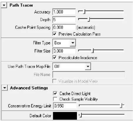
Figure 1.6 shows thePath Tracerinterface in the Maya Render Settings window.
Accuracy
Sets the number of paths that are traced for each sample element (pixel, texel or vertex). For preview renderings, you can use a low value like 0.5 or 0.1, which means that half of the pixels or 1/10 of the pixels will generate a path. For production renderings you can use values above 1.0 if needed to get good quality.
Depth
Sets the average number of bounces in the Path Tracer solution. The maximum depth is 40. A lower Depth will result in a faster but noisier solution, but the overall intensities will be the same. How far light actually bounces is much dependent on your materials, brighter materials lets light spread further than dark materials.
Cache Point Spacing
Sets the maximum distance between the points in the path tracer cache. If set to 0.0 a value will be calculated automatically based on the size of the scene. The automatic value will be printed out during rendering, which is a good starting value if the point spacing needs to be adjusted.
Preview Calculation Pass
If enabled the pre-render pass will be visible in the render view. Filter Type
Selects the filter to use when querying the cache during rendering. None will return the closest cache point (unfiltered).
Filter Size
Sets the size of the filter as a multiplier of the Cache Point Spacing value. For example; a value of 3.0 will use a filter that is three times larges then the cache point spacing. If this value is below 1.0 there is no guarantee that any cache point is found. If no cache point is found the Default Color will be returned instead for that query.
Precalculate Irradiance
Prefilter the cache points before the final pass starts. This can increase the performace using the final render pass and is especially useful whenCheck Sample Visibilityis enabled, or the filter kernel is large.
Use Path Tracer Map File
Selects how the cache points are saved or loaded from file. Overwrite will create a new map file. Reuse will load the cache points from the map file and skip the pre-render pass. Reuse and Refine will load the cache points from file but refine the solution by running the pre-render pass again.
File Name
Sets the name of the cache map file. The map file is saved inturtle/ptMapsin the current project directory.
Visualize in Model View
If enabled the cache points saved to file will be displayed in Maya’s model view after the rendering.
Cache Direct Light
When this is enabled the path tracer will also cache lighting from light sources. This in-creases performance since fewer direct light calculations are needed. It gives an approx-imate result, and hence can affect the quality of the lighting. For instance indirect light bounces from specular highlights might be lost.
Check Sample Visibility
Turn this on to reduce light leakage through walls. When points are collected to interpolate between, some of them can be located on the other side of geometry. As a result light will bleed through the geometry. So to prevent this Turtle can reject points that are not visible. Conservative Energy Limit
The Path Tracer needs to clamp the Maya materials so that they act in a physically accurate way. The Conservative Energy Limit parameter lets you set how tight the clamp is, where 1.0 would mean that a material is allowed to be exactly on the border of being non-physical. The default is 0.95, which means that the material is at most 5% below the critical limit. Default Color
Sets the color to be returned if no valid cache point is found during a cache query. If no points are found the Filter Kernel needs to be increased. By setting the color to e.g. bright red or green, you can easily see if a larger filter kernel is needed.
1.3.4
Monte Carlo
This is a brute force GI method that calculates GI by sending rays in a hemisphere around the shading points. No caching is used so a new calculation is done for each shading point. An importance sampling method is used for secondary bounces, so a high num-ber of bounces can be used without exploding the render time. This Monte Carlo method is unbiased and can be used for reference images when used as primary GI. It can also be used as secondary GI together with final gather to produce a multi-bounce high quality result without light leakage.
Figure 1.7: Monte Carlo settings
Rays
Sets the number of rays to use for each calculation. A higher number gives higher quality, but longer rendering time.
Depth
Sets the average number of indirect light bounces calculated by monte carlo. A lower num-ber means a noisier but faster solution, although the overall intensities will be the same. Max Ray Length
The max distance a ray can be traced before it’s considered to be a “miss”. This can improve performance in very large scenes. If the value is set to 0.0 the entire scene will be used. The distance is measured in Maya units.
1.3.5
Global Photon Map
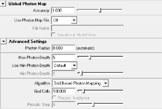
Figure 1.8 shows theGlobal Photon Mapinterface in the Maya Render Settings window.
Accuracy
Sets the number of photons to use when calculating global illumination effects. A higher number gives higher quality but takes a longer time to calculate.
Use Photon Map File
Enables usage of photon map files. By saving the photon map to a file, it can be reused in successive renderings. The file will be placed underturtle/photonMapsin the current project directory. Note that if lights or geometry is moved, recalculation is necessary. Off disables file usage. Overwrite creates a new photon map file, overwriting any existing file. Reuse loads the photon map from a previously created file.
File Name
Sets the filename of the global photon map file. Visualize in Model View
Visualize the stored photons as a point cloud in the Maya viewport. You can change point size and color in the attributes of the generated point cloud.
Figure 1.8: Global Photon Map settings
Photon Radius
Sets the maximum search radius to use when searching for photons during lighting calcula-tions for global illumination effects. If the Photon Radius is set to r, photons within a sphere of radius r around the sample point will be used to calculate the light. The radius is given in Maya units. If the Photon Radius is set to 0.0 a value will be calculated automatically based on the size of the scene. The automatic value will be printed out during rendering, which is a good starting value if the point spacing needs to be adjusted.
Max Photon Depth
Sets the maximum number of bounces a global photon can take before it is absorbed. Use Min Photon Depth
When set to Specified the user can specify a minimum number of bounces a global pho-ton must take before it is stored in the phopho-ton map. This can be used to alter the default global photon behavior, which is to store all photons when final gather is used and store all secondary photons when final gather is not used.
Min Photon Depth
Sets the minimum number of bounces a global photon must take before it can be stored in the photon map.
Algorithm
Selects which algorithm to use when calculating global illumination effects. Standard Pho-ton Mapping is more accurate but Grid Based PhoPho-ton Mapping is much faster.
Grid Cells
Sets the number of grid cells when Grid Based Photon Mapping is used. A higher number gives higher accuracy but longer rendering time. If the scene is very complex, a higher value may be necessary.
Precalc. Irradiance
When enabled, the irradiance will be precalculated at the photon positions before the ren-dering starts. This gives a much faster renren-dering at the cost of lower accuracy. If standard photon mapping is used with final gather, it is recommended to enable this feature.
Precalc. Step
Controls how often the precalculation is applied in the photon map. If set to 1 precalcula-tion will be done at all photon posiprecalcula-tions, if set to 2 at half of the posiprecalcula-tions, if set to 4 at one quarter of the position, etc. Hence a higher value gives faster rendering but less accuracy.
Note: By excluding the first one or two bounces from being stored in the photon map (using
Min Photon Depth) one can remove very bright areas, e.g., caused by sunlight through a window.
1.3.6
Dynamic Photon Map
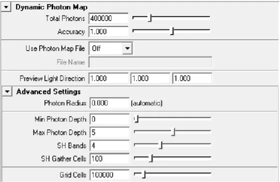
Dynamic Photon Maps are used for specific baking tasks, where light from any possible di-rection has to be considered. Photons will be emitted towards the scene from every possible direction, and stored using spherical harmonics in a grid structure. Figure 1.9 shows the
Dynamic Photon Mapinterface in the Maya Render Settings window.
Total Photons
Number of photons to be emitted into the scene. Accuracy
Sets the number of photons to use when calculating global illumination effects. A higher number gives higher quality but takes a longer time to calculate.
Use Photon Map File
Enables usage of photon map files. By saving the photon map to a file, it can be reused in successive renderings. The file will be placed underturtle/photonMapsin the current project directory. Note that if lights or geometry is moved, recalculation is necessary. Off disables
Figure 1.9: Dynamic Photon Map settings
file usage. Overwrite creates a new photon map file, overwriting any existing file. Reuse loads the photon map from a previously created file.
File Name
Sets the filename of the dynamic photon map file. Preview Light Direction
The preview of the Dynamic Photon Map is only meant to be used to fine tune the intensity of the indirect dynamic light for a baking pass, and will not produce any quality results. In a typical case, you turn off any other lights in the scene, giving you a rough picture of the influence you’ll get from the photon map (e.g. when baking color bleeding to a PTM). The Dynamic Photon Map contains photons from any possible direction; the Preview Light Direction specifies one such direction for evaluation of the map.
Photon Radius
Sets the maximum search radius to use when searching for photons during lighting calcula-tions for global illumination effects. If the Photon Radius is set to r, photons within a sphere of radius r around the sample point will be used to calculate the light. The radius is given in Maya units. If the radius is set to 0.0, an automatic value will be used.
Min Photon Depth
Sets the minimum number of bounces a global photon must take before it can be stored in the photon map.
Max Photon Depth
Sets the maximum number of bounces a global photon can take before it is absorbed. SH Bands
Number of bands to use for the spherical harmonics function in each grid cell. A higher number of bands will allow for more high frequent illumination data.
SH Gather Cells
Incoming photons are stored on their emit direction. This setting determines the number of buckets (each associated with a direction) that will be used for photon collection. Again, a higher number allow for information of higher frequency.
Grid Cells
Sets the number of grid cells when for the Dynamic Photon Map data structure. A higher number gives higher accuracy but longer rendering time. If the scene is very complex, a higher value may be necessary.
1.3.7
Caustics Photon Map
Caustics effects are handled with a special photon map in Turtle. You must explicitly emit caustics photons from light sources. Figure 1.10 shows theCaustics Photon Mapinterface in the Maya Render Settings window.
Figure 1.10: Caustics Photon Map settings
Accuracy
Influences the number of photons to use when calculating caustics effects, a higher number take more photons into account. Default value is 1.0.
Use Photon Map File
Enables usage of photon map files. By saving the photon map to a file, it can be reused in successive renderings. The file will be placed underturtle/photonMapsin the current project directory. Note that if lights or geometry is moved, recalculation is necessary.
• Off: Disables file usage.
• Overwrite: Creates a new photon map file, overwriting any existing file. • Reuse: Loads the photon map from a previously created file.
File Name
Sets the filename of the caustics photon map file. Visualize in Model View
Visualize the stored caustic photons as a point cloud in the Maya viewport. You can change point size and color in the attributes of the generated point cloud.
Photon Radius
Sets the maximum search radius to use when searching for photons during lighting calcu-lations for caustics effects. If the Photon Radius is set to r, photons within a sphere of radius raround the sample point will be used to calculate the light. The radius is given in Maya units.
Max Photon Depth
Sets the maximum number of bounces a caustics photon can take before it is absorbed.
1.3.8
Advanced Settings
Advanced GI Settings are controlled from here. Figure 1.11 shows what the interface looks like.
Ray Selection
Here you can set which GI solution each ray type should see. This can be used for optimiza-tion on ray type. For instance Glossy reflecoptimiza-tions generally does well with using the photon map directly instead of final gather.
Render Prepass Only
When enabling this, the rendering terminates after the GI prepass is done. This is useful if you want to distribute renderings between different computers. Typically you run through an animation perhaps, each 10th frame, on one computer with ”Reuse and append” file mode for the GI. You can then distribute this GI solution to a cluster of render nodes to avoid flickering GI in the animation. It can also be used to avoid seams between tiles when using many computers to render one frame.
1.4
Environment
The environment tab collects all the details for specifying the surrounding environment of your scene. You can set a specific environment for Global Illumination calculations, specify an environment for reflective or refractive objects and the background itself.
The Environment can be set to • None- Black
• Camera Background- Use the environment from the current camera • Sky Light- Use a specified color/texture for the entire environment • Image Based Lighting- Use a specified LDR/HDR image as environment Figure 1.12 shows theEnvironmentinterface in the Maya Render Settings window.
Intensity
Control the intensity of the specified environment. Visible in Background
Show the environment in the background of rendered frames. The alpha channel will still store transparent in areas with no geometry coverage.
Visible in Reflections
Show the environment in reflective surfaces. Visible in Refractions
Show the environment in refractive surfaces.
1.4.1
Sky Light
Sky Color
Specify a color for the Sky Light environment. Suitable to select a constant sky color, or plug-in a procedural sky like a ramp or a more complex shader network.
1.4.2
Image Based Lighting (IBL)
Image Based Lighting is both an algorithm to light a scene with a LDR/HDR image, and a simple environment for images. The IBL is by default set to act as a simple environment. Figure 1.13 shows theIBLinterface in the Maya Render Settings window.
Image File
The image file to be used. You can use most image types, but you should of course use an HDRI image if you can, like EXR or HDR.
Turn Light Dome
The sphere that the image is projected on can be rotated around the up axis. The amount of rotation is given in degrees.
Swap Y,Z
Swap the up axis. By default Y is up. Visualize
The HDR image will be visualized for reference as a sphere inside the Maya viewport. This sphere can only be turned around the up axis and is connected to theTurn Light Dome
Blur for GI
Pblur the environment image for Global Illumination calculations. Can help a lot to re-duce noise and flicker in images rendered with Final Gather. May increase render time as it is blurred at render time. It is always cheaper to pre-blur the image itself in an external application before loading it into Turtle.
Emit Light
Emit direct light from the environment by creating a number of virtual directional lights simulating the environment image. An alternative to this, which often is faster, is to use Final Gather instead so that the final gather rays extract light from the environment map. Emit Diffuse
To remove diffuse lighting from IBL, disable this check box. Emit Specular
To remove specular highlights from IBL, disable this check box. Samples
Sets the number of virtual directional lights created if Emit Light is enabled. This will affect how soft the shadows will be, as well as the general lighting. A higher number of samples, gives better shadows and lighting but increases the render time.
Intensity
Set the intensity of the lighting. Specular Boost
Further tweak the intensity by boosting the specular component. Enable Shadows
To create shadows, use this checkbox (also dependent onRay Tracing→Shadows).
Banding Vs Noise
Control the appearance of the shadows, banded shadows look more aliased, but noisy shad-ows flicker more in animations.
Emit Photons
Enables photon emission from the environment map. Caustics Photons
Global Photons
Number of global photons to be emitted into the scene. Photon Energy
The total photon energy.
1.5
Options
TheOptionstab hold render settings that you don’t need to adjust so often, e.g. settings for memory and performance, framebuffer settings and various overrides.
1.5.1
Memory and Performance
Figure 1.14 shows the Memory and Performanceinterface in the Maya Render Settings window.
Tile Scheme
Different ways for Turtle to distribute tiles over the image plane.
• Hilbert: A way for Turtle to achieve maximum coherence, e.g. the fastest rendering time possible.
• Left to Right: Render from left to right.
• Concentric: Starts in the middle and renders outward in a spiral.
• Random: A good way to get an early feel for the whole picture without rendering everything.
Tile Size
A smaller tile gives better ray tracing coherence but more inefficient shading. There is no “best setting” for all scenes.
Use one thread per CPU
Let Turtle automatically detect the number of available processors. Rendering Threads
Manually set the number of rendering threads. Use SSE
Turtle uses specialized vector instructions to speed up the rendering. The cost is higher memory usage. Turn off SSE/AltiVec if Turtle starts swapping memory.
Use Instancing
Enables use of instanced geometry, which saves memory. If disabled all instanced shapes will get a separate copy of the geometry, which might decrease render time, but increases memory usage.
Vertex Merge Threshold
Sets the threshold used for merging multiple face vertices into single vertices when loading scene geometry. If the difference of vertices is smaller that this threshold they are merged. This is used to optimize meshes data and decrease memory usage. The default value 0.001 should rarely be altered. Can be set to 0.0 to disable mesh optimization.
Enable Texture Cache
Selects whether the texture cache should be used or not. The texture cache works by stor-ing textures in a format supportstor-ing random access makstor-ing it possible to load them more efficiently. In scenes using large textures this will make the memory footprint of textures smaller and the texture loading faster. If disk space is an issue, the texture cache may be a problem since it stores copies of all textures.
Read Only Cache
If this box is checked, textures already in the cache will be used, but modified or added files won’t be cached.
Texture Tile Size
Sets the size of tiles in the textures. Smaller tiles will make the cache more memory efficient, but somewhat slower.
Texture Cache Size
Sets the maximum memory usage for the texture cache. Note it’s the memory used by the renderer, not physically on the disk.
Minimum Texture Size
Sets the minimum memory usage for a texture for it to be cached. It may be unnecessary to cache small textures that won’t use very much memory anyway.
Texture Compression Type
Sets what compression to use for textures stored on disk. The different compression types has different properties:
• None: no compression, gives high performance and large disk usage.
• RLE: Run Length Encoding. Gives good compression on images with large single colored areas.
• PIZ: a good compression type if using large tiles.
• ZIP: a versatile compression giving good results for texture maps in general. To learn more about the different compression methods, visit the open exr homepage (http://www.openexr.com)
Texture Cache Directory
Sets the directory in which the textures will be stored. A directory starting with “//” will refer to a directory in the project path.
Delete Cache
Pressing this button will delete all files in the texture cache. Recursion Depth
Recursion Threshold
Decides how many triangles that can reside in a leaf before it is split up. The Recursion Depth has precedence over the threshold. A leaf at max depth will never be split. The Recursion Depth and Recursion Threshold are advanced settings that shouldn’t be altered unless Acceleration Data Structures are second nature to you.
1.5.2
Frame Buffer
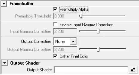
Figure 1.15 shows theFramebufferinterface in the Maya Render Settings window.
Figure 1.15: Framebuffer Settings
Premultiply Alpha
If this box is checked the alpha channel value is premultiplied into the color channel of the pixel. Note that disabling premultiply alpha gives poor result if used with environment maps and other non constant camera backgrounds. Disabling premultiply alpha can be convenient when compositing images in post.
Premultiply Threshold
This is the alpha threshold for pixels to be considered opaque enough to be “unmultiplied” when using premultiply alpha.
Enable Input Gamma Correction
Turtle renders everything in linear intensity space (not gamma corrected). This means Tur-tle assumes that all colors selected as inputs on Maya shaders are treated as linear, the same applies to all file textures. The output image produced by Turtle is also in linear space. If this is not desired Gamma Correction can be automatically applied to the input colors and textures, and to the output image. Example, the file textures are in gamma 2.2 and the re-sulting image should be in gamma 2.0. Setting input gamma to 2.2 will transform the input textures from 2.2 to 1.0 (linear space). Setting output gamma to 2.0 will transform the ren-dered image from gamma 1.0 (linear) to 2.0.
If some file textures are in linear space then input gamma correction can be individually disabled on the file texture nodes. HDRI file formats such as OpenEXR and Radiance HDR are always treated as linear.
Gamma correction, both input and output, applies to all render modes including Vertex Baking. The exception is Point Cloud Baking where the output file format is always consid-ered linear, and will thus ignore any specified output gamma correction.
Gamma correction is designed to correct colors with intensities between 0.0 and 1.0 between different display devices. Maya allows you to set color values with any possible brightness, but this will lead to very unpredictable results as a relatively limited color value might still be boosted to huge values by the gamma correction. You should always try to keep your col-ors limited, and useIntensitysliders where available, as scalar values will never be gamma corrected. This ensures that the color you see on your monitor will be transferred correctly to linear color space, and still have the boost in intensity that you want.
Input Gamma Correction
Selects the gamma space that input colors are assumed to be in.
Note: HDRI images are always considered linear.
Output Correction
This dropdown selects what kind of correction will be done to the output colors. • NONE Writes the linear colors directly
• Gamma Takes the linear colors to the gamma specified in Output Gamma Correction • SRGB Converts the colors to SRGB when showing them. This is similar, but not
iden-tical to gamma 2.2 Output Gamma Correction
Selects the gamma space the rendered image is transformed to. This is only considered when Output Correction is set to ”Gamma”.
Note: Point Cloud files are always written out with linear color space.
Dither Final Color
Check this checkbox if you want your images to be dithered when converting them from high dynamic range float to low dynamic range integer colors.
Output Shader
The image rendered can be post processed by applying an output shader. It can only op-erate on single pixels, one at a time and thus cannot do any advanced operations such as blurring or multi-pixel filtering. It is primarily used for gamma correction or color channel swapping.
To use, just apply a simple color utility to the shading box. When the shading network is finished, the nodeilrOutputShaderBackendNodemust be applied to tell where the shad-ing network should get its color information from. TheilrOutputShaderBackendNodeis described in section 4.3.1.
A simple example of an output shader could be:
• Connect a gammaCorrectNode to the Output Shader in the Render Globals. • Connect a ilrOutputShaderBackendNode to the Value of the gammaCorrect. • Set up the gammaCorrectNode accordingly.
• Render and enjoy your gamma corrected image.
Note: TheilrOutputShaderBackendNodemust be assigned in the shading network, oth-erwise Turtle does not insert the original image color correctly. Failure to do so will result in a black image.
1.5.3
Overrides
This section contains settings to globally override local settings. Figure 1.16 shows the Over-ridesinterface in the Maya Render Settings window.
Ignore Light Links
Sometimes Turtle will have troubles with light links. This will occur when there is a lot of geometry and a lot of lights and no light links available. Check this box to force Turtle to ignore light links.
Enable Quality Limits
Soft ray traced shadows and glossy reflections tend to increase render times and generally needs a lot of tuning to get a good result at a reasonable render time. Checking this box limits the number of rays for all light sources and glossy shaders in the scene disregarding the actual values on the shaders. This is useful when rendering previews of scenes to see the overall look before starting the final render.
Figure 1.16: Overrides Settings
Note: The Max Shadow Rays setting cannot be used to raise the number of shadow rays above the number set in the Shadow Rays setting for any light source, only to lower the limit. For example if Max Shadow Rays is set to 60 and Shadow Rays for a light source is set to 30, there will not be more than 30 rays per point for that light source. If Max Shadow Rays is set to 15 and Shadow Rays is set to 30, no more than 15 rays will be sent.
Min Shadow Rays
Use this value to ensure that you get enough quality in soft shadows at the price of render times. The setting sets a lower limit on the number of rays sent to determine whether a point is lit by a light source or not. This will raise the minimum number of rays sent for any light sources that have a Min Shadow Rays setting lower than this value.
Note: This setting cannot be used to lower the number if Min Shadow Rays for the light source is set to a higher value. For example if Min Shadow Rays for a light source is set to 10 and this setting is set to 5, there will be at least 10 rays sent, provided that the maximum limit of rays is not reached before that. Setting this to a value higher than Max Shadow Rays under Quality Limits or Shadow Rays for the light source will not send more rays than the minimum value of those two settings for that light source.
Flip for odd UV winding direction
Using this setting will force Turtle to mirror tangent and binormal when UV has odd wind-ing direction.
Vertex Level Orthogonalization
Orthogonalize tangent space basis vectors (tangent, binormal and normal) at every vertex. Vertex Level Normalization
Normalize tangent space basis vectors (tangent, binormal and normal) at every vertex. Intersection Level Orthogonalization
Orthogonalize tangent space basis vectors (tangent, binormal and normal) at every intersec-tion point.
Intersection Level Normalization
Normalize tangent space basis vectors (tangent, binormal and normal) at every intersection point.
1.5.4
Output Verbosity
Figure 1.17 shows theOutput Verbosityinterface in the Maya Render Settings window.
Figure 1.17: Output Verbosity Settings
Error
Prints error messages. Warning
Prints warning messages. Benchmark
Prints benchmark information. Progress
Info
Prints info messages. Verbose
Prints verbose information. Debug
Prints debug information. Used for development purposes. Save output to file
If enabled all output will be saved to the fileMAYA PROJECT PATH\Turtle\temp\debug.out.
1.6
Turtle settings on Maya nodes
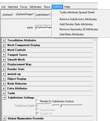
Turtle can render most standard Maya nodes using their native settings. In many cases those settings are sufficient but for a couple of Maya nodes Turtle also provide the opportunity to add extra settings to further affect their behavior. The nodes that can be complemented with extra Turtle attributes are geometry objects, lights, cameras, surface shaders, displacement shaders, file textures, shading engines and render layers. To add or remove extra Turtle attributes on these nodes simply open up the attribute editor for the selected node. From the menuTURTLEselect what to add or remove. The extra Turtle settings can then be found in the separate Turtle rollout in attribute editor. See figure 1.18
ATurtle attribute spread sheetis also available from theTURTLEmenu. The spreadsheet lists Turtle attributes for all objects in the current selection. This lets you edit the values of many attributes on many nodes at the same time.
1.7
Geometry Object Settings
See figure 1.19.1.7.1
Subdivision Settings
To use subdivision, check the Render as subdivision surface box located in the Turtle rollout in the shape attributes on your polygon object.
Turtle supports polygons with a maximum of 5 edges. Subdivision Depth
Controls the amount of subdivision that occurs. A higher value produces more polygons and a better result, but will also use more memory and increase render times.
Sharp Corners
Do not smooth the corners of an open mesh. A sphere is a closed mesh, a plane is an open mesh.
Figure 1.18: Turtle settings in attribute editor
Smooth UV
Checkbox for controlling UV-smoothing. This is enabled per default.
1.7.2
Renderstats
This section sets general parameters for the objects interaction with light. Smooth Normals
The normals of a mesh can be smoothed at render time. The normals are then calculated as the average of all vertex normals at the same vertex. A threshold can be used to only include normals which have a similar direction. The threshold is given as the maximum angle in degrees, between two normals, under which they will be averaged. This feature is useful in a variety of situations, including:
• When using Pre-Tesselated displacement you often need a very high tesselation set-ting to get a smooth looking surface. By smoothing the normals on faces that doesn’t have too sharp edges, you can get a smooth looking surface with much lower tessela-tion settings, hence saving both memory and render time.
• When calculating surface transfer from a mesh with face normals you will not get a continuous sampling since the sampling is performed along the normals of the mesh. So by using the Smooth Normals feature you can get a continuous sampling without having to alter the actual normals on the model.
Visible In Final Gather
Let the object affect final gather calculations. Static Final Gather
If enabled, the object will keep its final gather samples in RAM-memory between successive frames in an animation.
Smooth Final Gather
If enabled, the final gather solution will be smoothed for this object. If unchecked, the final gather smoothing will be disabled, which might save render time in some situations. Cast Global Illumination
If enabled, the object will reflect indirect light. Receive Global Illumination
If enabled, the object will receive indirect light. Cast Occlusion
If disabled, the object will be invisible for occlusion rays. Therefore, it will not cast any occlusion on other objects when the ilrOccSampler is used.
Receive Occlusion
If disabled, the object will not receive any occlusion from other objects when the ilrOccSam-pler is used.
Bias Shadow Rays
Enable Bias Shadow Rays to reduce shadow line artifacts on low-resolution geometry, see figure 1.20.
1.7.3
Global Illumination Settings
This section contains override settings for global illumination. Global Illumination Override
Checking this box allows you to override the settings of the Global Photon Map attributes
Photon Accuracy,Photon Radius,SaturationandIntensity for a particular object. For a complete explanation of these attributes seeGlobal Photon Map, section 1.3.5.
Final Gather Override
Checking this box allows you to override the settings of the final gather attributesGathering Rays,Accuracy,Smooth,SaturationandIntensityfor a particular object. For a complete explanation of these attributes seeFinal Gather, section 1.3.2.
Figure 1.20: Ray-traced shadows without and with Bias Shadow Rays
Caustics Override
Checking this box allows you to override the settings of the caustics attributesPhoton Ac-curacy,Photon Radius,Saturation and Intensity for a particular object. For a complete explanation of these attributes seeCaustics, section 1.3.6.
1.7.4
Bake Resolution Override
Checking this box allows you to override the settings of the texture baking attributesBake Res X,Bake Res YandBake Set Scalefor a particular object. For a complete explanation of these attributes seeBaking Reference, chapter 2.
1.8
Light Settings
1.8.1
Intensity Settings
Primary IntensityScales the light intensity for primary rays. Can be used to adjust or turn on/off the amount of light this light source emits on surfaces visible from the camera.
Reflection Intensity
Scales the light intensity for reflection rays. Can be used to adjust or turn on/off the amount of light this light source emits on surfaces visible in reflection.
Refraction Intensity
Scales the light intensity for refraction rays. Can be used to adjust or turn on/off the amount of light this light source emits on surfaces visible in refractions.
Indirect Intensity
Scales the light intensity for final gather rays. Can be used to adjust or turn on/off the amount of indirect light this light source emits.
Use Indirect Light
Any light source can now be turned into an indirect light. Behaves like a normal light, but instead of the standard light shader it uses the indirect (GI) solution as light shader. This way you can light link the GI, saturate the GI color, shape the GI in form of a spotlight e.t.c. Basically all controls you have on the direct light sources can be used to control the GI solution.
1.8.2
Decay Settings
Radius Of InfluenceSets a radius of influence for this light source. Inside the sphere spanned by the radius light is emitted as usual, but outside the sphere no light is emitted. This will also optimize shadow calculations since no shadow rays will be cast from surfaces outside the sphere. Use Custom Decay
Enable this if you want a light decay that is a function of the radius of influence. The fol-lowing formula will then be used to calculate the illumination:
illumination=color∗intensity∗[1.0−(distance/radius)d]f Distance Exponent
Controls thedexponent in the formula above. Can be used to adjust the shape of the light attenuation.
Falloff Exponent
Controls thefexponent in the decay formula above. Can be used to adjust the shape of the light attenuation.
1.8.3
Shadow Settings
Min Shadow RaysSets the minimum number of shadow rays used to determine the influence of this light source a any point. Use this setting to ensure that you get enough quality in the soft shadows for this light source at the price of render times. If this is set to zero, Turtle determines a good value for this setting, otherwise the number specified is used. Regardless of the value specified, there will never be more rays sent than specified in the Shadow Rays setting for
the light source or more than the Max Shadow Rays setting specified in the Overrides section of the Render Settings for Turtle.
Use Depth Map Shadows
Enables Turtles Depth Map Shadows. When this checkbox is enabled, Turtle will use the settings below for shadow calculation. If this checkbox is disabled and Maya’s Depth Map Shadows are enabled, Turtle will calculate shadows based on Maya’s Depth Map Shadows settings.
Resolution
Sets the resolution of the depth map used for calculating shadows. A higher resolution will give less aliasing but consume more memory. If a very soft shadow is desired, set a low resolution and use a large filter size.
Filter Size
The size of the blur filter kernel. A larger value will give a softer shadow. If a low resolution is set, a larger filter size is needed to reduce aliasing.
Samples
Sets the number of samples to use then applying the filter to get soft shadows. A higher value will give less noise but longer rendering time.
Bias
The bias used to reduce self-shadowing artifacts. If Mid Distance is used, this value can often be ignored.
Use Mid Distance
This is used to reduce self-shadowing artifacts. When this is enabled the average distance between the first and the second intersection will be stored in the depth map.
Use Depth Map File
Controls the usage of depth map files. By saving the depth map to a file it can be reused in successive renderings. Note that if the light or shadow casting objects are moved recal-culation is necessary. The file is written to the folderturtle\depthMapsin the current Maya project directory.
• Off: Disables file usage.
• Overwrite: Creates a new depth map file, overwriting any existing file. Reuse loads the depth map from a previously created file.
• Reuse and append: Loads the depth map from a file, but also writes back new depth map tiles generated during rendering.
Depth Map File
Sets the file name for the depth map file.
1.8.4
Global Illumination Settings
Contains settings for emitting photons. Emit PhotonsControls whether the light is a photon emitter or not. Photon Energy
The amount of photon energy emitted from the light. Caustics Photons
Number of caustic photons emitted from the light. Global Photons
Number of Global Illumination photons emitted from the light.
1.8.5
IES Settings
Turtle has support for light profiles on Maya point lights. With light profiles, you can eas-ily add real-life lights to your scene for greater realism. A light profile is a light intensity distribution specified by a texture map.
File Name
The file name of the IES Light profile to use. Turtle can read so called IES-files. Many manufacturers of lighting fixtures record photometric light intensity measurements of their products in IES-files and provide these for visualization purposes on their websites. Thus, there is a large number of interesting lights readily available on the internet. Some examples of IESfiles can be found at http://www.daybrite.com/day-brite/photometry.cfm.
IES Counter Clockwise
Enable this to reverse the horizontal angle of the light profile.
1.9
Camera Settings
Environment Camera
Under the Turtle tab on the camera there is an option to make the camera an ’Environment Camera’. When enabled the camera will render an environment map instead of the usual camera view. The environment will be rendered with the camera looking in the positive Z direction. The environment map will be created around the Camera Origin. The ’Type’ list box selects one of the following environment map types:
• Cube Map: The cube map rendered with Turtle is in ’Vertical Cross’ format. It is at the moment not compatible with the Maya ’Env Cube’ node since Maya uses six different textures for the sides of the cube map.
• Ball Map: The ball map is in the same format as the Maya ’Env Ball’ node expects. The ball map is not a very good format for environment maps, since the distribution of samples is very irregular.
• Spherical Map (LatLong): The spherical map (also called Latitude Longitude map) is in the same format as the Maya ’Env Sphere’ expects. This is the preferred format for creating and using environment maps with Turtle.
1.10
Material Settings
See figure 1.22.1.10.1
Glossy Reflections and Refractions
Glossy reflection/refraction simulates non perfect (blurry) reflections and refractions. The Glossy Reflection/Refraction settings are available for the Maya materials Phong, PhongE, Blinn and Anisotropic and are located in the Turtle roll-out in the material settings. The settings differ a bit between the anisotropic and the other shaders.
Glossy Reflections / Glossy Refractions Enable Glossy Reflections for this material. Maximum Rays / Maximum Refr. Rays
The maximum number of reflection rays to trace for an intersections point. A higher value gives less noise in the resulting image.
Sharpness / Refr. Blur Angle
How sharp the reflections are. A lower Sharpness value gives blurrier reflections. A higher Refr. Blur Angle value gives blurrier refractions.
Anisotropic / Refr. Anisotropic
Makes the glossy effects anisotropic, spreading out the reflected or refracted image nonuni-formly.
Use Maya Shader Angle Settings (Anisotropic Shader only)
Import the rotation of the anisotropic reflection/refraction from the shader settings to align them with the specular highlights.
Angle / Refr. Angle
Specifies the rotation of anisotropic reflections/refractions, note that it uses 360 degrees for a 180 degrees rotation to make the settings compatible with the angle settings for the anisotropic shader in Maya.
SpreadX / Refr. SpreadX
How much the reflections/refractions will spread out in the tangent direction. SpreadY / Refr. SpreadY
How much the reflections/refractions will spread out perpendicular to the tangent. Understanding Sharpness, Blur Angle and Spread
The tangents of the surface defines the direction in which the surface will look brushed when using anisotropic glossy reflections. Having a large value for spreadX will spread out the reflections/refractions along the tangents and a large value of spreadY will spread it out perpendicular to the tangents. If they are the same, the material won’t look anisotropic at all. The spread parameters are affected by the sharpness value. This means that it’s often a good idea to increase the sharpness vs. decrease the blur angle when turning on anisotropic reflections/refractions since it affects both spreadX and spreadY.
Note: A material with an inconsistent UV mapping will give a poor result.
1.10.2
Global Illumination
Primary IntensityScales the intensity of the first GI bounce for this material. Note that there is also a global control for this in Render Settings - Global Illumination - Color Balance.
Primary Saturation
Scales the saturation of the first GI bounce for this material. Note that there is also a global control for this in Render Settings - Global Illumination - Color Balance.
Secondary Intensity
Scales the intensity of secondary GI bounces for this material. Note that there is also a global control for this in Render Settings - Global Illumination - Color Balance.
Secondary Saturation
Scales the saturation of secondary GI bounces for this material. Note that there is also a global control for this in Render Settings - Global Illumination - Color Balance.
Diffuse Boost
If your material has very dark colors/textures, light will fall off very quickly in the Global Illumination. Increasing Diffuse Boost will push up t