c
The British Computer Society 2015. All rights reserved. For Permissions, please email: [email protected] doi:10.1093/comjnl/bxv051
Quality Assured Model-Driven
Requirements Engineering and Software
Development
László Lengyel
1,∗Tamás Mészáros
1, Márk Asztalos
1, Péter Boros
2,
Attila Máté
2, Gábor Madács
2, Péter Hudák
1, Kristóf Kovács
1,
András Tresch
2and Hassan Charaf
11Budapest University of Technology and Economics, Budapest, Hungary 2Quattrosoft Ltd, London, UK
∗Corresponding author: [email protected]
Software development requires adequate methods for requirements engineering, design, development, testing and maintenance. The more complex the system is, the more sophisticated methods should be applied. A significant part of software projects is short on appropriate require-ments engineering, communication, development and testing method, furthermore, verification and validation processes; i.e., not the right method is applied, and the project turns into ad hoc design and development decisions. This paper introduces our quality assured model-driven requirements engineering and software development method. The method is based on the modeling of the software requirements in a way that these models can be used to automatically generate several artifacts during the engineering process. This method is continuously developed during the last 12 years driven by our software projects. In the last two years, we have developed new tool support and also reworked the method. In this paper, as an experience report, we introduce the method: a framework to specify software requirements with four domain-specific languages and automated solutions to process the models. We focus on the requirements engineering method of the whole development cycle. We also report the lessons learned and share our best practices on the field of model-driven
requirements engineering and software development.
Keywords: software modeling, requirements-engineering, requirements modeling, model-driven methods, communication platform
Received 11 April 2014; revised 15 May 2015 Handling editor: Mariangiola Dezani-Ciancaglini
1. INTRODUCTION AND MOTIVATION
Developing software artifacts in enterprise environments should be based on mature methods. Software products drive almost all parts of our life. However, software development methods and the methods supporting the whole process still can be made more adequate. Appropriate approaches are required to support unambiguous requirement definition, capturing and defining user processes, making possible effective develop-ment that results in quality products, and verifying/validating the requirements. Adequate requirement engineering and anal-ysis [1,2] can define the obvious project scope and result in the
agreement between the customer and the developer team dur-ing the project and also in the end when deliverables should be adjudged and accepted. The unambiguous requirement spec-ification, being formal enough, can drive the whole software project, including the development, testing, documentation generation and maintenance as well. Furthermore, it is still important to be able to accept the continuous changes and run an iterative agile process cost effectively [3].
There are several issues in the system development that moti-vates software architects and developers to work out and use different methods. Notable motivating issues are the problem
of informal requirements specifications and the consequences of the ad hoc project scope. These issues can result in misun-derstandings and losing the control over the project. We have assembled a few points that further drive our activities and motivate us to develop and apply more advanced and adequate techniques in the development process:
(i) Inadequate requirements analysis method: the rele-vant customer processes are not or under analyzed. As a consequence, they are not addressed properly by the provided solutions.
(ii) Ambiguous scope definition: a textual description of the requirements can easily mean different things for the customer and the solution providers. Without languages that are formal enough and understandable both for the customer, i.e. domain experts, and the software experts, the scope of the project and the real requirements can easily become unclear.
(iii) Only software functions are defined but domain pro-cesses are not analyzed: this issue assumes that the software drives the business and not the business requirements define the software functions.
1.1. Overview of our methods
From the beginning, which goes back to the previous decade, our vision was to develop software systems with a methodology that targets and supports the followings:
(i) Techniques supporting effective requirements engi-neering that ends with formal user stories which can be validated by the customer. This means that the customer understands the specification, because it uses the domain concepts and defines their business processes.
(ii) Domain-specific languages that are applied to define use cases, user stories (the business processes that are required to be supported), domain dictionary and the high level requirements. The languages facilitate cross-references between the model elements, i.e. referring domain concepts and requirements from use case models and activity models (user stories). (iii) A method to build the semantic model based on the
business processes defined by the user stories. (iv) A technique to generate as much of the source code
as possible from the requirements specification. The generated code is based on supporting libraries that are continuously developed by senior developers. The generated code covers those parts of the imple-mentation that are very similar in each projects, e.g. data management (database-related function-alities, concurrency management), communication between the client and the server. Of course, there is custom logic, which is difficult to express on
the model level, therefore, the related code is not generated.
(v) Each requirement is connected to the model ele-ments that define the software development activity even if it is generated or implemented manually. This makes possible to follow the modifications and apply the required changes during the whole lifecycle of the system.
(vi) A technique to automatically generate relevant test scenarios for the manually written modules based on the formal user stories was introduced above. The meaning of the relevant test scenario will be discussed later in the paper.
(vii) A technique to automatically generate formal but user readable documentation, i.e., the documentation is also driven by the identified user stories, automat-ically generated and validated by the customer. The documentation includes the detailed specification that is easy to read and validate by the end users. Based on the documentation, the representatives of the customer can decide if the specification meets their business requirements.
(viii) A method to ensure the continuously up-to-date state of the semantic model (requirements specification) all along the lifecycle of the given solution.
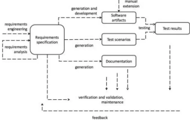
This paper introduces a domain-specific modeling and model processing-based method for supporting effective software development. The method covers the whole development process, including requirements engineering, development, testing and documentation as well. In this paper, the focus is on the requirements engineering method and tools. Figure 1 introduces the main concept of the suggested requirements engineering and development method. The requirements engi-neering and analysis result in the Requirement specification, which is a collection of models that are both human read-able and formal. This means that these models can be easily understood by domain specialists (customers) and also formal
FIGURE 1. Overview of the requirements engineering and develop-ment method.
enough to serve the software artifact generation. The specifica-tion includes use cases, activity and further models collecting the user requirements. These models define the high-level requirements, the domain vocabulary, the use cases and the detailed user stories. The stories are step-by-step scenarios defining the exact algorithm (workflow) of the business pro-cesses that should be covered with the solution. Based on the requirements specification we generate the software artifacts, the relevant test scenarios and documentation as well. The source code is manually extended by custom logic after gen-erating the frame and the general components: data access layer, communication, first version of the user interface and the integration of the prepared library components, i.e. logging, security, others. The testing performed on the executables is based on the automatically generated test scenarios. The verifi-cation and validation, performed on the generated and manually extended software products, is also based on the requirements specification.
These all mean that the well-defined requirements specifica-tion drives the whole process. This is one of the most important points of the entire method, i.e. the requirements specifica-tion is in the focus: the customer and the developer team agree on the scope of the project with the help of the requirements specification models. Next, this specification drives the whole process: we always go back to the specification and derive each of the required artifacts based on it. The method pro-vides an iterative process: the continuously gained experience and the feedback improve the requirements specification and therefore influence the next iteration as well: newly generated and altered software artifacts, test scenarios and the refreshed documentation.
We apply the method to develop three layered software sys-tems: database, business logic and web-based or desktop user interface. During the last 12 years several projects required and supported to develop class libraries that make the artifact gener-ation effective and robust as well. This means that the generated artifacts are the SQL scripts of database creation, data access layer to perform the database related create, read, update and delete methods, the frame of the application both on the server side and the client side. Furthermore, well-parameterized lists of function calls as the derived process workflows and business logic are also generated. These function calls are targeting class library methods that are developed by senior developers and are well tested. These libraries are the result of several year development and more than a dozen of different projects. The goal is to reuse them because of their stability. We apply differ-ent Java techniques to perform all these. The generated source code is extended manually and also utilizes different class libraries, therefore, the requirements models driven testing is careful.
The whole method is applicable for different fields, for example, for embedded system development, but based on the previous notes, it requires to perform several projects on the field and manually build the supporting class libraries,
furthermore, work out and maintain the appropriate model processors that generate the artifacts utilizing these libraries.
1.2. Impact of the applied methods
In the following, we present our vision about how our model-based development methods developed in the last decade are able to improve certain aspects of the software engineer-ing process. Our overall goal with the method is to increase the quality of the produced artifacts, the effectiveness of the requirements engineering, the unambiguity of the project scope and development, and the customer satisfaction.
The scope of the method is as follows:
(i) To identify which characteristics of the system to be developed determine if the suggested method can be applied for it. Bysystem characteristics we mean the size of the system under development, the architecture (e.g. web client, server, DB layer), the technology (e.g. Java) and the development method (e.g. waterfall, agile, other). We examined numerous software development technologies and methods to be able to provide as generic method as possible. (ii) To identify the target audience. The key is in the
length of the lifecycle. The longer the software sys-tem is maintained, the more changes must be applied during the lifecycle. By having a well-understandable software model, the changes can be introduced at a significantly lower cost. We believe that this affect can produce shorter return of investment (ROI) period if the method and the tooling are harmonized. Our experiences show that our methodology aims bigger systems that require careful modeling, exact processes and workflows, furthermore detailed documentation and deep testing. Such target audience can be bank-ing applications, civil service, public administration, insurance companies, medicine factories etc. (iii) A method supporting to define software
specifica-tions on the level of abstraction high enough for the domain experts and the further engineering pro-cess. The method and the tools should produce the documentation and the basement of the following development activities. Therefore, it provides a com-monly used communication platform between the participants of a software development project. (iv) The method and the provided supporting tools should
be effective enough to make it easier to follow the process than to sabotage it. In general, the overall goals of software projects are well-known, and every software expert understands their needs and agrees with them. But they still follow the ‘ad hoc’ approach, usually saying that we do not have enough time to be systematic. We believe that an effective method and the appropriate tool support can break this habit.
1.3. Structure of the paper
We have strengthened the motivation of our work by discussing the challenges from the field of requirements engineering and software development. We have also provided a high-level overview of the methodology we have developed.
The rest of this paper is organized as follows:
(i) Background is summarized in Section 2. We discuss the techniques we applied to achieve our goals, i.e. introduce the domain-specific modeling and model processing with their benefits.
(ii) Section 3 introduces our model-based requirements engineering method and provides our experience-based thoughts. We present a modeling framework with four domain-specific languages. These languages make it possible to specify models of various soft-ware requirements. Besides the conceptual overview of the models, the implemented tool support is also discussed.
(iii) Section 4 shows how the models can be used during the development process and how our methodology improves the engineering process. We overview the techniques that starting from the requirement mod-els automatically generate source code, relevant test scenarios and documentation. The model processing is not in the focus of this paper, therefore, we only summarize it from a bird’s eye view. We mainly con-centrate on the requirements engineering part of the method.
(iv) Section 5 summarizes the lessons we learned during we worked out the method: we discuss the strengths and the consequences of the method, furthermore, we provide a detailed list about the techniques and best practices we have applied successfully.
(v) Finally, conclusions are elaborated in Section 6.
2. BACKGROUND
This section provides motivating examples and highlights the need for effective methods in the field of software development. The two key points in application development are evergreen: make the development effective and provide high quality arti-facts. Model-driven approaches address both of these issues.
2.1. Model-based development
Nowadays, modeling is a key concept, which facilitates the system definition and supports better communication on the appropriate abstraction level. Furthermore, system models are the first-class artifacts in model-based development. Modeling and model-based development gather several fields, such as UML [4], domain-specific modeling, multi-paradigm model-ing [5], generative programmmodel-ing [6] or model processmodel-ing [7–9].
The growing size and complexity of software systems made software modeling technologies essential in application development. This is an observable trend to move from uni-versal modeling languages towards domain-specific solutions. Domain-specific languages (DSLs) [10,11] are strictly limited to a domain, but this limitation makes it also possible to be much more efficient than a universal language could be. Using domain-specific artifacts and enforcing the domain rules auto-matically makes DSLs useful not only for software developers, but also for domain experts.
Based on precise, formal models, the automatic generation of complete application layers or even the entire application came to reality [11]. The most popular model processing methods are model traversing processors, template-based processors and high-level model-to-model transformations [8,12]. Traversing processors provide a mechanism to visit the internal represen-tation of the model [13]. Traversing processors are often used for code and document generation and they are usually sup-ported by a script or template language. Template-based model processing is very effective if the goal is to generate textual output, for example, configuration file, XML file or source code. Model-to-model transformations often represent the pro-cessing of input models and the generation of output models in a high abstraction level, for example by using the modeling languages of the models themselves [14]. High-level model-to-model transformations are usually based on mathematical graph rewriting that can be applied if the model is represented as a graph that has a solid formal specification, which makes the verification and the validation of the transformation and the output much easier.
Model-based software development (MBSD) is an increas-ingly applied method in producing software artifacts. MBSD is driven by model processing that is attempted to bridge the semantic gaps between high-level models and low-level lan-guages [7]. The benefits of the model processing-based methods are the more flexible, efficient and configurable development solutions, the increased efficiency of the development and the high quality of the software products.
2.2. Requirements engineering
Requirements engineering [1] is the process of formulating, documenting and maintaining software requirements. Require-ments engineering has a significant role in successful software engineering processes. Requirements analysis in software engi-neering encompasses those tasks that go into determining the needs or conditions to meet for a new or altered software product or artifact, taking into account the possibly conflicting require-ments of the various stakeholders, analyzing, documenting, validating and managing software and system requirements.
The IEEE Standard Glossary of Software Engineering Technology [15] defines a software requirement in the
following way:
(i) A condition or capability needed by a user to solve a problem or achieve an objective.
(ii) A condition or capability that must be met or pos-sessed by a system or system component to satisfy a contract, standard, specification or other formally imposed document.
(iii) A documented representation of a condition or capa-bility as in 1 or 2.
In the field of requirements engineering, there are several widely used concepts and approaches, which thoughts and val-ues are worth to be considered and adapt some practice from them. These concepts and approaches are as follows: business requirements, requirements analysis, requirements manage-ment, requirement prioritization, requirements traceability and user stories.
Business requirementsare what must be delivered to pro-vide value. Software, information systems, further software and non-software products and processes are the wayshowto meet or satisfy thewhats of the business requirements. The topic of business requirements usually arises in the context of developing software systems.
Requirements analysisin the field of software engineering includes all those tasks that help to identify the end user needs and the conditions that should be addressed by the developed product. Requirements analysis should take into account the surrounding conditions and the requirements of the various stakeholders [1]. Requirements analysis is a critical phase in software development and has a significant effect on the suc-cess of the whole project. The requirements should be clearly documented, measurable, testable, traceable, transparently related to certain business needs, and defined to a level of detail sufficient for system design.
Requirements managementis a continuous process through-out a software development project. Requirements manage-ment addresses several activities: documanage-mentation, analysis, tracing, prioritizing and agreeing on requirements. Further-more, requirements management controls change requests and handles the communication between the relevant stakeholders. In software product management,requirement prioritization is used for determining which requirements of a software prod-uct should be included in a certain software package (release). Several methods for assessing a prioritization of software requirements exist; usually these methods prefer the most important and high risk requirements.
Requirements traceability documents the life of the user requirements and provides bi-directional traceability between various associated requirements. These methods enable users to find the origin of each requirement and track every change that was made to this requirement [16].
In software development, auser storyis few sentences that captures what a user does or needs to do as part of his job function. User stories are usually written in the everyday or
business language of the end user. User stories capture the basis for defining the functions a software system must provide, and to facilitate requirements management. User stories capture the who,whatandwhyaspects of a requirement. Functional user stories are formed by business users. To express non-functional requirements (e.g. security, performance, quality, others) user stories are extended by developers as well.
User stories are an effective way of handling customer requirements without creating formalized requirement descrip-tions and without managing and administrating them. The intention of the user story is to be able to respond faster and with less overhead to rapidly changing business require-ments [17].
Our method, introduced in this paper, notably benefits from the user stories by defining and applying them in a formal way. Besides the user stories, requirements analysis, requirements engineering and requirements management also contribute a significant part to the presented quality assured software devel-opment method. Furthermore, there are approaches that also influenced our method, these are story-driven modeling and domain-driven design.
Story-driven modeling[18], a high-level graphical method, employs so called story boards to analyze the dynamics of object structures as sequences of graphical snap shots for sam-ple scenarios. The major benefit of the approach is that story boards allow to develop and illustrate design and ideas of a sys-tems object structure and central mechanisms in a quite simple visual notation. On the other hand, story boards have well-defined syntax and semantics that gives way to semi-automatic derivation of subsequent specifications like, e.g. the static class hierarchy and dynamic operations on object structures. Story-driven modeling supports analysis, design and imple-mentation of software components. Story-driven modeling is not intended to replace existing modeling techniques like UML but to complement them. Story-driven modeling has proven to work well for the cooperation with non-IT experts.
Both story-driven modeling and our approach, presented in the paper, address these goals, i.e. to provide a ubiquitous language (one or more DSLs) that is understandable for both the domain experts and requirement analyzers, enough formal to define precisely the user requirements, capable to define the dynamics of object structures as sequences and can be automatically analyzed and processed. The difference is that our approach is driven by not only the need to analyze and formally define requirements that is understandable for the domain experts as well, but this is a tool to be able to effectively support the development by artifact generation, the testing by test scenario generation and also the maintenance phase of the software lifecycle.
Domain-driven design [19] as a software development approach supports complex requirements by connecting the implementation to an evolving model. Domain-driven design places the project’s primary focus on the core domain and domain logic, bases complex designs on a model of the
domain and initiates a creative collaboration between technical and domain experts to iteratively refine a conceptual model that addresses particular domain problems. Domain-driven design does not specifically require the use of a DSL, though it could be used to help define a DSL and support methods like domain-specific multimodeling. The emphasis is put on to understand and build the domain model. This is common with our approach, i.e. to understand and define the domain related processes and derive the system behavior from it. Both of the approaches define that a system based on the domain model and rules is easier to understand, use and extend.
2.3. Domain-specific languages
Domain-specific languages are an effective way to narrow the communication gap between the customer and the devel-oper team. DSLs can form that common language which is understandable for the customer and has useful meaning for development purposes. To raise the level of abstraction in model-driven development, both the modeling language and the model processors (generators) need to be domain-specific.
With a domain-specific language, the problem is solved only once by modeling the solution using familiar domain concepts. The goal is to define the end user requirements with the help of domain-specific languages. These models are the final artifacts in the development process that are understandable for the tomer, therefore, these artifacts are the last step where the cus-tomer can validate his requirements. Also, these models are the first step where developers understand the operation of the sys-tem in a formal way. As a consequence, these models should drive the whole development process, i.e. we should derive all the functionalities, the documentation and also the test scenar-ios from these models. This requires that our DSLs provide con-structs and enough details for all these issues to be defined, while remain understandable for domain experts.
Our DLSs, theUse Case DSL, theActivity DSL, the Require-ments DSLand theConcept DSL, are extensions of different UML models: their roots are the different UML diagrams, but we have modified their abstract syntax (metamodel), concrete syntax, and we have added custom semantics to them. Handling them in this way, these DSLs drive our model-based system development process.
3. DOMAIN-SPECIFIC LANGUAGES FOR REQUIREMENTS ENGINEERING
We have developed four DSLs, which provide an exten-sive toolset to facilitate the description and collection of the requirements in an efficient way:
(i) Use Case DSL: to describe the actors and the use cases of software systems.
(ii) Activity DSL: to describe the workflows’ use cases related to specific user and test case scenarios. (iii) Requirements DSL: a dictionary of the requirements to
make it possible to reference them from other models. (iv) Concept DSL: a glossary of domain related concepts
that can be referenced from other model elements. The tool support of the method is implemented in the Eclipse Framework [20] as an Eclipse plugin and further model processing components. We discuss the metamod-els of the domain-specific languages, introduce the plugin, which is based on the eclipse graphical modeling framework (GMF) within the frame of eclipse graphical modeling project (GMP) [21]. Furthermore, we share some details about the realized editor using the eclipse extended editing framework (EEF) [22].
We have chosen the Eclipse Framework as the implemen-tation platform, because Quattrosoft Ltd. uses it as its default implementation environment. Their software projects are mainly implemented on Java platform. Alternative implemen-tation environments could be for example generic modeling environment (GME) [23], DSLTools [24] or an optional cus-tom tool. This means that the methods and the domain-specific languages provided by the presented methodology are tool independent, i.e. the results and the methods can be applied in different environments as well.
The domain-specific languages not only support the qual-ity assured model-driven requirements engineering method, but also serve as a basis for generating software artifacts. First, we introduce the common elements of the four model-ing languages, and then present the concept of each language separately. Finally, tool support for efficient management of the models is detailed. The processing of the models, i.e. the methods that generate code, documentation and test scenarios are addressed in Section 4.
3.1. Common elements of the DSLs
The four DSLs have a common tree view editor interface, a table view and a more intuitive graphical view for visual edit-ing. These DSLs are an improved and expanded version of the ubiquitous UML use case and activity models [4]. We have modified the original UML languages, because we wanted them to fit our needs to specify the requirements, these mod-ifications are based on our experiences distilled from several industrial case studies. Our improvements make the formu-lation of user stories a simplified process. We used eclipse modeling framework (EMF) to describe the metamodels.
The four DSLs are realized as one monolith metamodel because of the requirement to be able to mix the model elements from the different domains into one instance model as well. All languages are based on a common metamodel fragment that is depicted in Fig.2. Each element of the metamodel derives from AbstractTypethat facilitates the unified handling of all model
FIGURE 2. Metamodel of the common language elements.
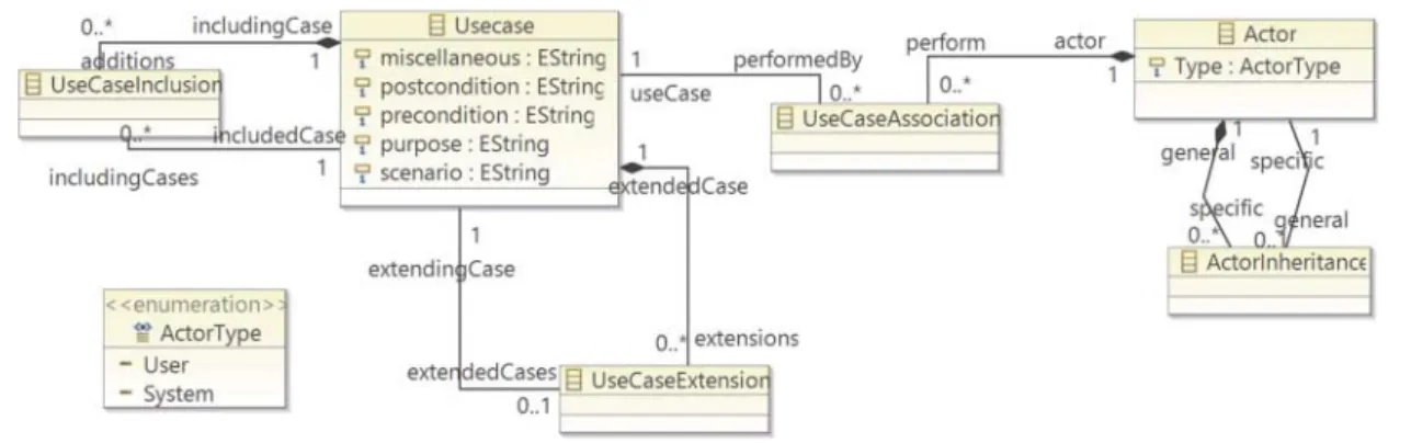
FIGURE 3. The use case metamodel.
elements: each model element has aname, areal name(to pro-vide a more meaningful name), a uniqueid, adescription, and asortorderthat specifies priority during documentation gen-eration for a specific element. Thedescriptionfield contains a rich text description (in XML format) that may contain cross references to other model elements as well. This weak ref-erence (stored in the XML document) is also expressed with modeled references (referencingEntities/referencedEntities edges) to be able to discover dependencies without parsing all the XML descriptions as well. The descriptions may embed images as well, this dependency is expressed by the Attached-Image element (that points to a file-system element) and the imagesrelationship.
According to the metamodel, all model elements can be orga-nized intoPackagesthat may also correspond to real Java pack-ages during code generation.
3.2. The use case and the activity DSLs
The Use Case DSL is a model of how users connect to and interact with the system to handle problems. The DSL describes the goals of the users, the interactions between the users and the system, and the required behavior of the system to satisfy these goals. The two main elements of the language are theUseCaseand theActor(Fig.3). Note that all the elements in this metamodel inherit from theAbstractTypeelement, so they all have aname, adescription, can be referenced etc.
UseCasesalso have the usualprecondition, postcondition, purposeandscenarioattributes to precisely define the use case. The attributes also contain rich text content in XML format,
may contain references to images or cross references to other model elements.UseCasesmay include and extend each other corresponding to UML.
By Actors, we distinguish User and System actors (ActorType) to be able to differentiate between the differ-ent actors interacting with the system.
Models can be edited in the usual EMF tree view-based model editor, however, we can assign diagrams to any of the packages as a root elemenet, and visualize a model fragment in a graph-ical way as well. We may place elements contained by another package than that of the diagram root onto the digram, however, in this case the element is placed as ashortcut(that is indicated by an arrow on the top of the element). By deleting a shortcut, the element itself is not deleted from the model. Also a shortcut is created when a model element is placed on the same diagram for a second or third time, e.g. to increase transparency.
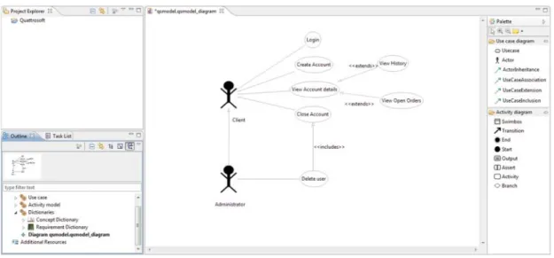
The complete DSL diagram editor application consists of theProject Explorerview, anOutlineview (orNavigator win-dow), a drawing area (diagram) and the palettes, which provide the toolset for placing elements on the drawing area (Fig. 4). Elements can be inserted by clicking on an appropriate element on the diagram palette and dropping it to the drawing view. The navigator window is used as an instant summary of our model as a tree view. We can add, modify and delete new elements here and diagrams as well.
TheActivity DSLis used to display a sequence of activities. It is useful both to formalize user stories and also to define test scenarios for validation. The metamodel of the language is provided in Fig.5. The user story or test workflow starts at aStartnode, finishes at anEnd node and each step (activity)
FIGURE 4. A sample use case diagram.
FIGURE 5. The activity (user story) metamodel.
describes the test case to perform or the expected behavior in textual, human readable format (descriptionfield). Activities are connected with Transition edges that simbolize a condi-tional (guard attribute) transition between two activities. In addition to simple activities, we distinguish two special kinds of activities as well:Assert andOutput.Assert describes the main purpose of the test scenario, i.e. the condition that must be satisfied in order to say that the test has been successfull. The Output node denotes an activity where the testing user must produce some kind of output (a screenshot or a print), and attach it to the test log. These two special kinds of activities are used to ephasize their roles on the user interface for the user
and they are also taken into account later, for example, during the automated test generation.
All these techniques, based on the actity model, support the identification of relevant test cases. Activity and use case models represent the business processes and the system level use cases. These models serve as a communication platform at an appropriate level of abstraction. These artifacts can be transformed to human readable and understandable documen-tations. Therefore, these artifacts are typical products of the requirements handling and definition project phases. Based on the customer feadbacks, we found that using our DSLs, the model and the generated documenntation are compact and
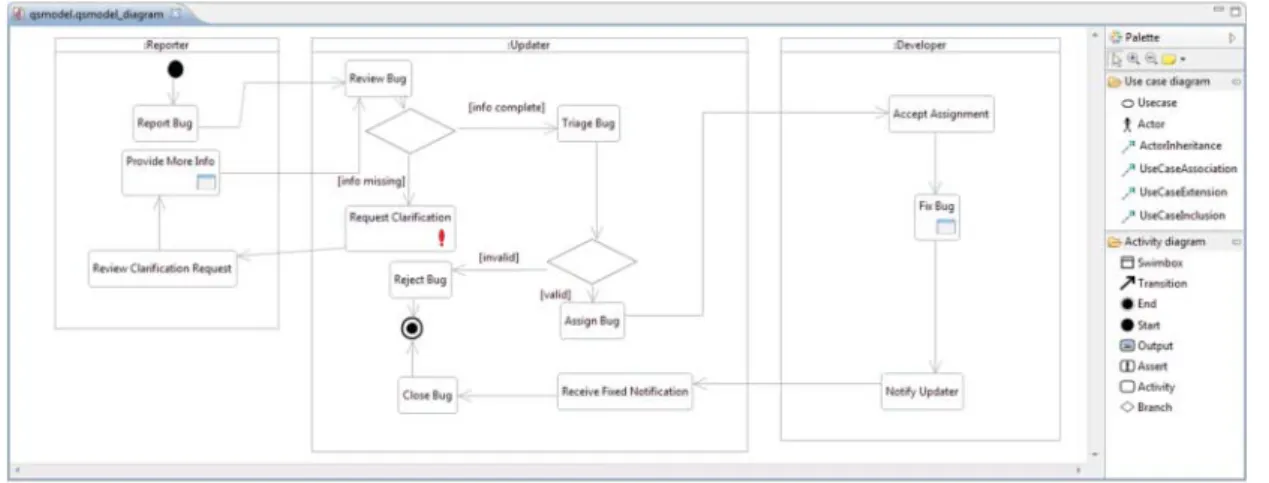
FIGURE 6. A sample activity diagram.
unambiguous. The formal definition of the DSLs makes pos-sibe to use their keywords as instructions during the analysis of the activity graph.
Activities may be hierarchical as well: an activity can be spec-ified in more details in another activity diagram. The end nodes of the contained activity model can be mapped to the leaving transitions of the container activity node (originatingEnd refer-ence), thus, we can specify which transition to follow for each end state of the contained scenario.
To be able to organize activities by actors within a model, we have introduced a special element calledSwimbox. Swimboxes are similar to swimlanes (like in UML Sequence diagrams) with the difference that they can be freely aligned on the screen thus we can achieve optimal layout. Each swimbox can be connected to one specific user and a system actor.
For an activity, we can also exactly define those use cases real-ized by the activity (realizedUseCasesedge), and for each use case, we can assign a complete activity model, if the use case can be performed by a complex workflow. An example activity model is depicted in Fig.6.
3.3. The requirements and concept dictionary DSLs
TheRequirements DSLand theConcept Dictionary DSLmake it possible to summarize all the related concepts and requirements of an actual software product. The metamodels are provided in Fig.7. The implementation provides these dictionaries in a table format.
The different dictionaries can be embedded into our model hierarchy. After creating the dictionaries in the tree view of the model editor, we can edit them both in the table view and in the tree view. The table view processes the actually opened model and organizes the related information to display the dictionaries in a practical format in table cells.
The Concept dictionary is a glossary of domain related concepts. We can refer to these concepts from other model
FIGURE 7. The requirements and the concept dictionary metamodels.
elements, such as activities or actors, and we can look up those model elements, in which these concepts are affected. An example concept dictionary is presented in Fig. 8, where the concepts are provided both in a tree control and in a table format: name of the concept and the related description.
User requirements are collected in the requirements tables. The links between the requirement items and model elements help us to follow which model parts realize a certain require-ment, and vice versa, which requirements are affected by a model element. The layout of the requirements dictionary matches that of the concept dictionary.
3.4. EEF-based rich editing features
The EEF [22] is a presentation framework for the EMF. EEF makes possible to create rich user interfaces instead of the default grid-like property editor panels to edit EMF mod-els. The realized EEF-based rich editor is a great help during the modeling. The capabilities of the realized EEF editor are discussed in this section.
In addition to being able to edit the usual model element properties, we can edit the textual model properties with the help of a rich text editor. Using this control, we can apply
FIGURE 8. A sample concept dictionary specification.
FIGURE 9. The EEF editor of an actor object.
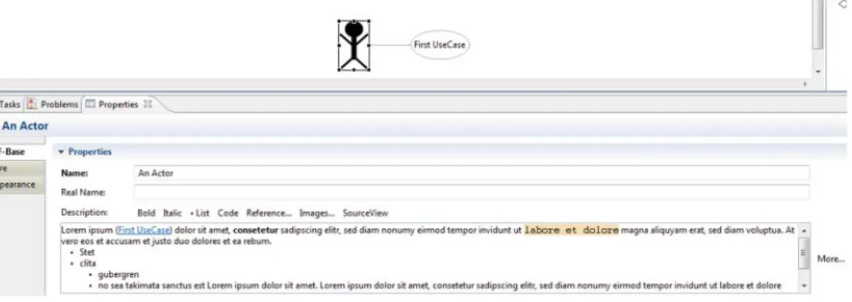
different font styles (bold, italic) in the text; we can apply bulleted lists, and mark text fragments as source code with special formatting. References that refer to model elements (e.g. an actor or activity) can be inserted into a text as cross references. Besides, the images provided by the file system (the eclipse workspace is the root directory) can also be inserted as references. Figure9depicts the EEF editor interface for an Actorelement. The bottom part of the figure shows the custom rich text editor.
The formatted text is converted and stored in XML format that mostly uses the well-known HTML tags. The XML format of the text is available and editable in theSourceViewof the edi-tor (Fig.10). Pressing theMore. . .button, a larger dialog win-dow pops up and makes possible the more comfortable editing of the text.
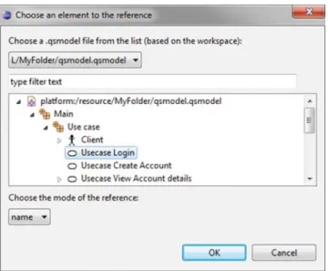
A separate dialog has been developed to serve the reference management (Fig. 11). The window represents the model elements in the hierarchy they are stored in the model. By selecting a model element the solution puts a refer-ence into the source view of the text (e.g. <a href = “/My Folder/qsmodel.qsmodel# _h8XcYDfgEeOAZYngIZUwOw” mode =“name”/>, where the code after the hashmark char-acter denotes theunique id of the referenced model element), and shows the value of theNameattribute of the referred model element in the rich text. The name is shown as blue underlined expression, and by moving the mouse over the name of the referred element, a tooltip shows the path related to the model element (Fig.12).
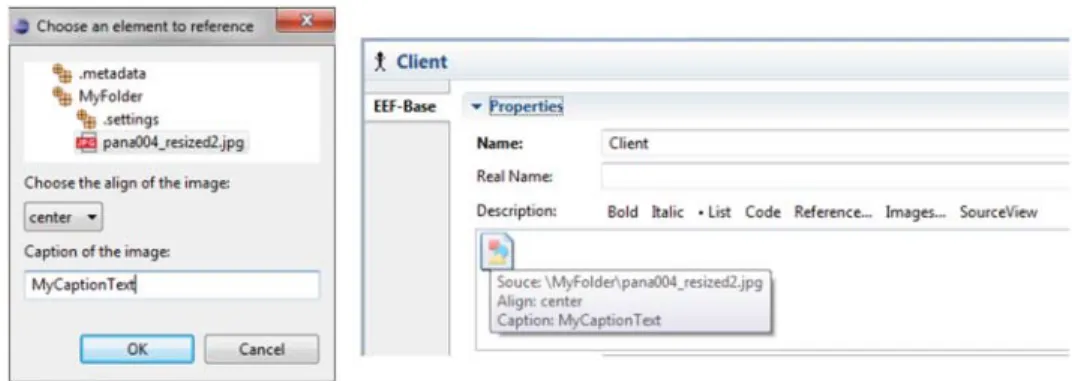
In a similar way, we can refer to images as shown in Fig. 13. By selecting an image the solution puts a
FIGURE 10. The SourceView of the editor.
FIGURE 11. The reference chooser dialog window.
FIGURE 12. Tooltip of a referred element.
reference into the source view of the text (e.g. <img align =“center”caption =“MyCaptionText” src=“\MyFolder\ pana004_resized2.jpg”/>), and shows an image placeholder. The tooltip of the placeholder shows the path of the referred image file.
With the help of the realized editor interface, we are able to describe use case descriptions, activity operations, etc. in a WYSIWYG format, and we can insert image references and cross references to elements. The presented solution provides a comfortable way to manage cross references that can be
resolved during the generation of the documentation, while it also maintains a formal model in the background that facilitates finding dependencies between various requirements and their implications.
3.5. Further domains of the environment
Through a software development process, all the gathered information pieces should be organized in a carefully designed repository structure. Usually, the information is represented by plain text documents and stored in separated repositories main-tained by the different project partners. This method results in extra administration cost during the software development process. Unfortunately, this type of administration should be performed by highly qualified experts, because all information has its semantic meaning. Misunderstanding the meaning of information can lead to communication problems and further issues. Therefore, applying the appropriate DSLs and provid-ing a consistent workprovid-ing environment for the experts, we can significantly reduce the unnecessary administration and allow experts focusing on their main objectives.
We have defined several further DSLs for the rest of the soft-ware development process. All DSLs are about to capture the appropriate level of abstraction and help the communication between domain experts and software engineers. These DSLs support the task management, definition of business entities, user interfaces, etc. We have mentioned them to provide a gen-eral overview, but the details of these DSLs are out of the scope of this paper because here we concentrate on the requirements engineering part and its tool support of the whole development cycle.
Project tasks are automatically derived from the domain-specific models and provide an easy way to follow the connec-tions between the requirements and the daily activities. The well-formed domain models support automatic code genera-tion. This is important that in this case the code generation is not equivalent with the visual programming technology. Domain models capture a higher level of abstraction than source code. Models support the designer to make high-level decisions. Code generators extend the models with platform-specific and implementation related details.
Business entities of the software systems are defined within a separate DSL. The instance models of this DSL refer to
FIGURE 13. The image browser dialog window and a sample inserted image placeholder with a tooltip.
relational database models. We also defined a DSL for cap-turing the graphical user interface requirements. During the definition of our DSLs, we aimed that the different DSLs can refer to each other. As a result, different domain models can refer to each other, and they utilize the objects and constructs of each other.
4. GENERATING SOFTWARE ARTIFACTS
Previous section has discussed the requirements engineering part and introduced the supporting environment of our method. As we have already mentioned in the introduction section, the model processing is not in the focus of this paper, there-fore, we only provide a summary about it, i.e., in this section, we shortly introduce the model processors that based on the requirement model set generate different artifacts: source code, tasks, documentation and relevant test scenarios.
4.1. Source code and task generation
The requirement models serve as a plan for all the activities done by different roles of the software development process. They act like a design layout for a building. We found that ideally the great majority of the development-related tasks should be generated from the models. The more tasks are gen-erated from the models, the less inconsistency can be observed between the model and the reality. Therefore, the first step is to solve the automatic and tool supported relationship between the model elements and the tasks. The next step is to identify which tasks are well-defined and can be expressed as decision points in domain models. For these cases, we can address the generation of the given software artifacts. We believe that this approach is quite important and should be followed; otherwise, a ;l’art pour l’art; effort could be taken: generating something that is not relevant or making all the decisions already in the model space.
We apply source code generation to process the following domain models:
(i) From business object models, we generate the object persistency layer of the system.
(ii) From the abstract user interface models, we generate the appropriate client source code.
(iii) Furthermore, other artifacts are automatically pro-duced like language resources and messages based on the terminology of domain models. It is impor-tant to handle this issue in an automatic way, because the same labels, domain expressions and messages should be generated in the documentation, in the source code and on the user interface as well.
4.2. Generating relevant test scenarios
Based on the business processes and the use case scenarios, the test cases are produced by traversing the process graph and identifying its different paths. The processing generates the so-calledrelevanttest scenarios. A relevant test scenarios represent a subset of the complete test scenario set. The solu-tion makes possible to define test data sets that are harmonized with the decision points and the process graph. By exhaus-tively traversing the whole process graph, we can generate all the test scenarios. However, in case of knowing certain deci-sions (parameters or variable values) we should test only those branches of the whole process graph that can occur. This makes the testing process more effective, because the known param-eters and variable values cut the problem space. For example, consider the following: there is a decision point, where we can choose between the red and green paths. Assume that we select the green one (e.g. based on an input parameter). Later, if the same decision arises, we should follow the same path again. Therefore, there is no need to generate test scenarios covering the red path. In this way we can reduce the number of test cases and ignore the unnecessary ones. The method, based on the use case scenarios generates a template for possible input param-eters. This is an Excel table. The user fills out this table and based on it and the use case scenarios the solution generates the relevant test scenarios.
4.3. Generating documentation
In our approach, domain models drive the whole development process. However, end user artifacts are mainly documents, which are the readable layouts of the given domain models. The business process models are a communication platform between the development team and the project stakeholders. Therefore, the documentation generated based on these mod-els should be well-formed, and furthermore, easy to read and understand for the domain experts. To fulfill this requirement, the business process model and every further DSL sections have their own documentation layout. The generator uses a template-based technology by writing the document directly through a Java API. The generator can produce documents of several hundred pages within a few seconds, i.e. the document generation solution is effective. Note, that it is not a goal to generate verbose and too long documents. The length of the documents depends on the sections related documentation lay-out, the size of the processed domain models, and the document format settings (e.g. font size, margins and further paragraph settings).
Model element descriptions are formatted as rich text sections; furthermore, they handle inserted images as well. Therefore, the generated document artifacts do not require any post-processing like manual formatting or extending.
5. LESSONS LEARNED
The result of this systematic approach leads to a close relation-ship between the original requirements, the source code, the documentation and the test cases used in the transition phase of the project. Based on our experience, the method signifi-cantly reduces the project risks. Based on this method, in the last twelve years, all our projects were delivered successfully. A further benefit was that the change management was also supported with a strong method. This is not trivial to calculate the direct and indirect benefits of the whole method, but calcu-lating with the 15% of the project cost is a good estimation. We highlight, that this ratio is an estimation by our senior archi-tects and technical project leaders. This benefit is related to the development phase of the software artifact’s lifecycle and it is calculated based on the last 12 years. The typical devel-opment phase of these projects is between 6 and 24 months. Furthermore, there is also benefit provided by the method that is realized during the maintenance of the software. The benefit is the result of the modularized, well tested and clean code. We are about to extend the method with certain well-defined points in order to be able to measure the benefits related to the whole development and maintenance phases more precisely.
As a general rule, both parties (the customer and the solution provider) are interested in defining the system requirements as precisely as possible. Our projects proved that extra efforts (e.g. a careful design) performed at the preliminary phase save more efforts in the transition phase and significantly reduce the
risks. This was our main goal during developing and applying this method.
The next two subsections discusses the strengths and weak-nesses of the approach, furthermore, provide a comprehensive list of best practices we suggest to apply for model-driven requirements engineering and model-driven development.
5.1. Advantages and disadvantages of the method
The strengths of the method:
(i) Requirements models drive the whole development process: requirements analysis and requirements engineering, artifact generation (development related tasks, source code, test scenarios, and doc-umentation), testing, verification/validation issues, maintenance and feedback management. This results a model-centered and strictly model-driven approach with advantages of clear requirements management and direct connections and consequences during the development process.
(ii) Provides the frame of adequate analysis, unambigu-ous scope definition and involvement of the domain experts (customers) into the development.
(iii) Defines a clear connection between the requirements and the software components (system functionalities). (iv) Puts the domain processes (workflows) into the focus
of the requirements analysis and the development. (v) Ensures the continuously up-to-date state of the
requirements models all along the lifecycle of the given solution.
(vi) The method and its supporting tools are effective enough to make both the domain experts and devel-opers life easy when they are working with them. (vii) The method can be freely extended with optional
number of DSLs and domain-specific model proces-sors. The key concept is that models should drive the artifact generation, the testing process and also the maintenance.
The weaknesses of the approach:
(i) The generated source code is based on company-specific class libraries. Some of these libraries are developed for different application domains (e.g. financial sector, governmental sector, pharmaceutical field, other) but the great majority of these libraries cover enterprise software related issues, i.e. sup-port the communication between the clients and the server, the data access and database management practices. These libraries are company-specific arti-facts, therefore, the generators should be redeveloped by each company in order to target their own library capabilities.
(ii) The maintenance of the metamodels, the modeling tool and model processors brings the evolution into
the process, but also require a reasonable amount of development effort. Based on the collected experience and requirements stated by the development process, targeted platforms or the natural need to extend the methods to address further aspects of the software systems, i.e. add new domain-specific languages to the modeling part, our team regularly improves and/or extends the DSL metamodels. Furthermore, the underlying company-specific class libraries are also evolving with different components distilled from our projects. These two changing factors require to maintain both the modeling environment and also the model processors reading the models and gener-ating the artifacts. We perform these modifications on a yearly basis.
(iii) Technology changes also have an effect on the modeling tool and model processors. Technology change means the evolution of the host modeling environment, i.e. the appearance of new versions or extensions of the base environment. An example for the technology evolution is the attendance of the Sirius technology, which is a novel way to define our own graphical modeling tools in Eclipse. It lever-ages the Eclipse modeling technologies, including EMF for the model management and GMF for the graphical representation. We found that Sirius tech-nology can make the design phase more productive with improved graphical representations to better elaborate and analyze a system and improve the com-munication with other team members, partners or customers. Therefore, we decided to adapt this tech-nology. As a consequence this requires reasonable maintenance in our DSL plugins. This also has a side effect for the model processors that need to be revised.
(iv) The provided method is presented as an experimental report, and not as a tutorial or a receipt to follow. The reason is that each developer company or team has its own rules and processes. The introduced method is not about to redefine the working method, but it suggests those thoughts, methods and assets that are worth to follow in order to make the software development process more effective and increase the quality of the resulted artifacts. Section 5.2 pro-vides general best practices that are also applicable by different companies and teams.
(v) The paper does not provide the exact details of the method. The reason is that we think about this paper as an experimental report. In the industry, there are dozens of company-specific decisions and solutions. We think that it is more useful to provide an overview and only some details about the method, especially related to artifact generation, because developer teams are interested in the general concept and not the
implementation details. They have their own imple-mentation preferences and they usually do not use out-of-box solutions, but implement the methods on their own way.
There are situations when the legal entities or other reg-ulations force a certain level of validation. We had several projects in the field of pharmaceutical, financial and govern-mental sectors. These projects required theoretically proven and verified approaches to confirm the correctness of the vali-dation process for the auditor organization. As an example, we mention a project from the pharmaceutical filed, where factory level processes, implemented in the newly introduced ERP system, was validated by the presented method and with some supporting tools.
5.2. Best practices for model-driven requirements engineering and model-driven development
We have learned several practices from different design and development approaches and during the years and based on our projects we have combined them with our experi-ence. In this section, we provide a distilled list with our short explanations.
Requirements modeling helps us understand, discuss, and communicate our customers’ needs by drawing diagrams about their activities and the part their system should play in helping them achieve their goals. A requirements model is a set of these diagrams, each of which focuses on a different aspect of the customers’ needs. We use the requirements model to help in the following way:
(i) Describe the users’ and stakeholders’ needs with much less ambiguity than we can in natural language. i.e. reduce gaps and inconsistencies in the requirements. (ii) Define a consistent, ubiquitous glossary of terms that
can be used by users, developers, and testers. (iii) Plan the order in which features will be developed. (iv) Reduce the work needed to respond to requirements
changes.
(v) Use the models as a basis for system tests, making a clear relationship between the tests and the require-ments. When the requirements change, this relation-ship helps us update the tests correctly. This makes sure that the system meets the new requirements. (vi) Separate the system’s external behavior from its
internal design.
Lessons learned and best practices that are worth to take home:
(i) Continuously keep the design up to date. A require-ments model provides great benefit if we use it to focus discussions with the users or their representa-tives, and revisit it at the beginning of each iteration.
Revisiting the design is a part of an agile-like method, i.e. at the beginning of each iteration we go through the design, think it over and do the neces-sary modifications to address the actualities. This is similar to the backlog analysis and adjustment of the user story priorities.
(ii) Clearly understand users’ needs. Creating a model usually results in a significant reduction in inconsis-tencies and ambiguities in the users’ requirements. Different stakeholders frequently have different understandings of the business world in which the system works. Therefore our first task is to resolve these differences between our users. i.e. the starting point of any design is a clear understanding of the users’ needs.
(iii) Develop iteratively. Ideally, we know all require-ments in advance, however, usually this is not the case. As a consequence we often should apply an iterative method.
(iv) Use components. Breaking down a system model is the appropriate way of design and development. This promotes ability to test individual components before they are integrated into a larger system. (v) Model visually. Use diagrams to represent all major
components, users and their interaction. We found that many questions about the business domain arise naturally while we were creating a model. By putting these questions to our users, we can signifi-cantly reduce the need for changes at a later stage in the project.
(vi) Dedicate time to review the design to minimize con-ceptual (semantic) errors. Verify quality. The design team should ensure that major conceptual elements of the design have been addressed. The design should be unambiguous and consistent. Always make test-ing a major part of the project at any point of time. Testing becomes heavier as the project progresses but should be a constant factor in any software product creation.
(vii) Apply continuous integration. Prepare the method to control the changes. Several projects are cre-ated by different teams, sometimes with different background and in various locations, even different platforms may be used. As a result it is essential to make sure that changes made to a system are synchronized and verified constantly.
(viii) Consider alternative approaches. We should con-sider alternative approaches, evaluating each based on the requirements of the problem, the resources available to accomplish the project.
(ix) The design should be traceable to the analysis model. A single element of the design model often reflects to multiple requirements. Therefore, it is necessary to
have a way for tracking how requirements have been satisfied by the design model.
(x) The design should not reinvent the wheel. Develop-ment time is short and resources are always limited (we can utilize them for different purposes as well). Systems should be constructed using a set of design patterns. Design time should be invested in working out truly new ideas and integrating those patterns that already exist. Patterns support the understandability and maintainability of the system.
(xi) The design should follow the domain as it exists in the real world. The structure of the software design ideally mimics the structure of the prob-lem domain. That is, we minimize the semantical distance between the software and the targeted domain. This supports both the development and the maintenance.
(xii) The design should be uniform. Format, rules and style should be precisely de?ned for the design team before the design work begins. As a result the design should appear as it would be developed by one person. Best practices related to model-driven development [25]:
(i) Model the requirements, not the solution. Use or adapt the UML or design DSL(s) that describe the users’ requirements. We should avoid designing the notation according to the different aspects of the implementa-tion.
(ii) UML or DSL? (i) Try to apply UML. (ii) Consider cre-ating your modeling notation by using stereotypes to extend UML. (iii) Define a DSL if there is no UML diagram that fits the purpose. Important: avoid break-ing the rules and semantics of the UML.
(iii) Model the variant aspects. Analyze the implemen-tation and identify the aspects that can vary, either between one deployment and another, or over time as requirements change. These aspects should be mod-eled and then derived from requirements and design models.
(iv) Separate concerns. If the variable aspects can be divided into independent areas, use separate model types for each area. For example, use cases, pro-cesses, business entities, user interfaces, further aspects should be modeled separately.
(v) Generate or interpret? If the requirements for a par-ticular deployment rarely change, generate source code from the model, build it and execute it. If the requirements might frequently change, or might co-exist in more than one variant in the same deploy-ment, develop the application in a way that it can read and interpret the model or the configuration file derived from the models.
6. CONCLUSION
In this paper, using an experimental report form, we have intro-duced our requirements engineering and software development method. We have provided a strong motivation that has driven our research and development activities related to the method. Next, we have introduced the architecture and the details of the method. Furthermore, we have discussed our domain-specific modeling languages that support the effective requirements engineering. In addition, we have reviewed the model proces-sors generating the human readable end-user documentation and the relevant test scenarios. Finally, we have provided quite a comprehensive list of lessons learned and best practices related to model-driven requirements engineering and model-driven development.
We started to use the presented method or certain parts of it in our software projects more than ten years ago. Of course, the method and its tool support are being continuously developed and adapted to the actual conditions of different projects.
The introduced method has various benefits for the industrial partners. By applying quality assured methods in requirements engineering, user story definition, and requiring customer validation of the business requirements, significantly pushes forward the unambiguous project scope definition, the appro-priate quality assurance, and the customer satisfaction. We believe that this method can improve the quality of the software artifacts, increase the development productivity, and decrease the required resources and the time-to-market period.
The methods and the introduced domain-specific languages are tool independent, i.e. the results and the methods can be applied in different environments as well. Of course, we con-tinuously use the method, refine it and develop it tool support. This activity is driven based on our current software projects and novel experiences.
FUNDING
This work was partially supported by the Hungarian Govern-ment, managed by the National Development Agency, and financed by the Research and Technology Innovation Fund (grant no.: GOP-1.1.1-11-2012-0260).
REFERENCES
[1] Sommerville, I. and Kotonya, G. (1998)Requirements Engineer-ing: Processes and Techniques. John Wiley, Inc. New York, NY, USA.
[2] Pohl, K. (2010)Requirements Engineering: Fundamentals, Prin-ciples, and Techniques. Springer.
[3] Manifesto for Agile Software Development (2001) http:// agilemanifesto.org/(accessed May 15, 2015).
[4] OMG UML specification, Version 2.3 (2010) OMG document formal/2010-05-03, 2010.http://www.uml.org/ (accessed May 15, 2015).
[5] de Lara, J., Vangheluwe, H. and Alfonseca, M. (2004) Meta-modelling and graph grammars for multi-paradigm Meta-modelling in AToM3.J. Softw. Syst. Model.,3, 194–209.
[6] Czarnecki, K. and Eisenecker, U.W. (2000)Generative Program-ming: Methods, Tools, and Applications. Addison-Wesley. [7] Amrani, M., Dingel, J., Lambers, L., Lúcio, L., Salay, R., Selim,
G., Syriani, E. and Wimmer, M. (2012) Towards a Model Trans-formation Intent Catalog.Proc. 1st Workshop on the Analysis of Model Transformations, pp. 3–8, ACM, New York, NY, USA.
[8] Mens, T. and van Gorp, P. (2006) A Taxonomy of Model Transformation. Proc. Int. Workshop on Graph and Model Transformation, pp. 125–142. Electronic Notes in Theoretical Computer Science, 152.
[9] Sendall, S. and Kozaczynski, W. (2003) Model transformation: the heart and soul of model-driven software development.IEEE Softw.,20, 42–45.
[10] Fowler, M. (2010) Domain-Specific Languages. Addison-Wesley Professional.
[11] Kelly, S. and Tolvanen, J.P. (2008)Domain-Specific Modeling: Enabling Full Code Generation. Wiley-IEEE Computer Society. [12] Czarnecki, K. and Helsen, S. (2006) Feature-based survey of
model transformation approaches.IBM Syst. J.,45, 621–646. [13] Vajk, T., Kereskényi, R., Levendovszky, T. and Lédeczi, Á.
(2009) Raising the Abstraction of Domain-Specific Model Translator Development.Proc. 16th Annual IEEE Int. Conf. and Workshop on the Engineering of Computer Based Systems. San Francisco, USA, pp. 31–37.
[14] Ehrig, H., Ehrig, K., Prange, U. and Taenzer, G. (2006) Funda-mentals of Algebraic Graph Transformation. InMonographs in Theoretical Computer Science. Springer.
[15] IEEE Computer Society (1990)IEEE Standard Glossary of Soft-ware Engineering Terminology. IEEE Standard.http://standards. ieee.org/findstds/standard/610.12-1990.html(accessed May 15, 2015).
[16] Gotel, O. and Finkelstein, A. (1994) An Analysis of the Require-ments Traceability Problem.Proc. 1st Int. Conf. Requirements Engineering, pp. 94–101.
[17] Davies, R. (2011) Non-Functional Requirements: Do User Stories Really Help?http://www.methodsandtools.com/archive/ archive.php?id=113(accessed May 15, 2015).
[18] Norbisrath, U., Jubeh, R. and Zündorf, A. (2013)Story Driven Modeling. CreateSpace Independent Publishing Platform. [19] Evans, E. (2003)Domain-Driven Design: Tackling Complexity in
the Heart of Software. Addison-Wesley.
[20] Eclipse Framework (2014) http://www.eclipse.org/ (accessed May 15, 2015).
[21] Eclipse Graphical Modeling Project (2014)http://www.eclipse. org/modeling/gmp/(accessed May 15, 2015).
[22] Eclipse Extended Editing Framework (2014)http://www.eclipse. org/modeling/emft/?project=eef(accessed May 15, 2015). [23] GME: Generic Modeling Environment (2008)http://www.isis.
vanderbilt.edu/Projects/gme/(accessed May 15, 2015). [24] Domain-Specific Language Tools (2013)http://msdn.microsoft.
com/en-us/library/bb126327.aspx(accessed May 15, 2015). [25] Jacobson, S. (2002) The Rational Objectory Process—A
UML-based Software Engineering Process. Rational Software Scandi-navia AB.