Tram Concept for Skåne
Basic vehicle parameters
REPORT 2012:13 VERSION 1.3 2012-11-09
Spårvagnar i Skåne
Visiting address: Stationshuset, Bangatan, Lund
Postal address: Stadsbyggnadskontoret, Box 41, SE-221 00 Lund [email protected] | www.sparvagnariskane.se
Document information
Title Tram Concept for Skåne
Report no. 2012:13
Authors Nils Jänig, Peter Forcher, Steffen Plogstert, TTK; PG Andersson & Joel Hansson, Trivector Traffic
Quality review Joel Hansson & PG Andersson, Trivector Traffic
Client Spårvagnar i Skåne
This report illuminates some basic tram vehicle parameters for the planned tramways in Skåne. An important prerequisite is to define a vehicle concept that is open for as many suppliers as possible to use their standard models, but in the same time lucid enough to ensure that the vehicle will be able to fulfil the desired functions and, of course, approved by Swedish authorities.
The report will serve as input for the continued work with the vehicle procurement for Skåne.
The investigations have been carried out during the summer and autumn of 2012 by TTK in Karlsruhe (Nils Jänig, Peter Forcher, Steffen Plogstert) and Trivector Traffic in Lund (PG Andersson, Joel Hansson). The work has continuously been discussed with Spårvagnar i Skåne (Marcus Claesson, Joel Dahllöf) and Skånetrafiken (Claes Ulveryd, Gunnar Åstrand).
Lund, 9 November 2012 Trivector Traffic & TTK
Preface
0. Summary 1
1. Introduction 5
1.1 Background 5
1.2 Planned Tramways in Skåne 5
1.3 Aim 5
1.4 Method 6
1.5 Beyond the Scope 7
1.6 Initial values 8
2. Maximum Vehicle Speed 9
2.1 Vehicle Technology and Costs 9
2.2 Recommendations 12
3. Mechanical Aspects 14
3.1 Minimum Horizontal and Vertical Radii 14
3.2 Structural Concepts 16
3.3 Low Floor Proportion 19
3.4 Bogies and Chassis 22
3.5 Wheel Set Load 24
4. Power Supply and Energy Storage Devices 26
4.1 Existing Technologies 26
4.2 Possible Mixtures of the Various Systems 34
4.3 Economical Aspects 34
4.4 Recommendations 35
5. Energy Efficient Vehicles 37
5.1 Technological Requirements 37 5.2 Market Situation 38 5.3 Economical Aspects 38 5.4 Recommendations 39 6. Cost Implications 40 6.1 Investment 40
6.2 Vehicle Energy Consumption 42
6.3 Wheel-Rail Wear 42
6.4 Maintenance 43
7. References 45
0. Summary
The aim of this report is to describe different technical solutions in order to find which type of trams that is best suited for Skåne. The following recommenda-tions are made.
Maximum Vehicle Speed
It is recommended to opt for a maximum speed of 80 km/h. From the rolling stock perspective this is the economically and technically favoura-ble solution.
Mechanical Aspects
Minimum Horizontal and Vertical Radii
For horizontal radii it is proposed to use 40 m as a “preferred minimum” for the infrastructure and 25 m as an “absolute minimum” which the trams should be able to manage on the general route. Furthermore, 22 m may be used as an “absolute minimum” in depots and stabling areas.
A vertical minimum radius of 1000 m is proposed as the normal design value for the infrastructure and 625 m as a minimum for the vehicles.
All these values should be included in a future vehicle tendering document, with the minimum values being strict requirements (for the trams) and the preferred minimum values (for the infrastructure design) as information only.
Structural Concept
The vehicle concept affects ride comfort, vehicle investment and wheel-rail wear;
However, no requirement for a certain technical solution should be made in the technical specification;
An evaluation scheme should be used which gives more points to vehicle concepts utilising pivoting bogies and fixed axles on powered axles.
Low Floor Proportion
It is recommended to require a low floor proportion of a minimum of 70 % in the vehicle specification, to keep the possible vehicle types that can be offered as variable as possible.
Passenger doors close to the vehicle ends are not desirable, even on a 100 % low-floor vehicle, as they can contribute to longer dwell times.
Bogies and Chassis
Vehicle concepts with pivoting bogies and fixed axles between the wheels (as a minimum on the powered axles) perform best in terms of long term maintenance cost based on the authors’ experience;
However, it is not recommended to make a specific requirement for a certain technical solution in the tender documentation.
The evaluation system should be geared such that vehicles which are expected to incur higher maintenance cost would receive lower scores. In addition to better scores for pivoting bogies and axles, the amount of un-sprung mass should also be considered.
Wheel Set Load
Include a maximum static wheel set load of 110 kN in the specification.
Provide an evaluation system which will penalize but not exclude a proposal up to a maximum value of 120 kN and vice versa provide the possibility to achieve extra points for a reduced load.
Power Supply and Energy Storage Systems
Overhead power supply should be used as far as possible and ideally on the complete network. It provides the most economical solution to supply power to electrically propelled rail vehicles;
The procurement should be kept as open as possible and no solution should be chosen leading to a monopoly of one manufacturer, which means that solutions such as APS from Alstom or Primove from Bombardier are not viable options;
Further investigations should embrace a holistic view on the power supply system, as this is not purely a vehicle issue. The viability of energy storage devices on the vehicles depends on which other energy saving measures that are implemented in the power supply system. One feasible option, however, is that the vehicles could be equipped with supercapacitors.
Energy Efficient Vehicles
The empty vehicle mass should be considered as part of the evaluation criteria for the vehicle procurement with manufacturers offering a lighter vehicle with otherwise the same functionality achieving a higher score.
It should also be considered how the manufacturers can be held to their “promise” concerning vehicle mass during the bid phase. One possibility could be to link a contractual payment to achieving the vehicle mass docu-ment in the manufacturer’s bid which would be reduced if the intended mass is exceeded.
Cost Implications
Investment
Ideally for Skåne a joint procurement should be carried out, including a fleet size of at least about 15 to 25 vehicles as a firm order and the remain-ing vehicles as options.
Furthermore, it would be ideal to procure all urban and interurban vehicles for the Skåne region within one procurement process including both firm orders and options. This increases the likelihood of achieving a good price as it would provide economies of scale due to the order size which would outweigh any potential slight cost increases due to the requirements for both urban and interurban operations.
Energy Consumption
The traction power supply system should be carefully designed to allow for a high degree of brake energy recovery within the 750 V DC power supply system.
Traction energy consumption is dependent on the operational regime on the various lines and is predominantly a function of the vehicle mass.
Wheel-Rail Wear
Small radii should be avoided as far as possible on the infrastructure alignments;
Only one rail head geometry should be used for the whole network both for grooved and vignole rail (e.g. S49 vignole and 59Ri2 grooved rail);
A wheel profile fitting this rail head geometry should be used;
An evaluation scheme should be utilised favouring rolling stock concepts with pivoting bogies and fixed axles.
Maintenance
Include a requirement in the tenders for the manufacturers to provide exchange times for major components;
Test these exchange times under “real life” conditions following delivery of the tram (to ensure accurate numbers in the bid);
1. Introduction
1.1 Background
The region of Skåne is together with the three cities Malmö, Helsingborg and Lund cooperating for an introduction of new tramway lines in Skåne, in the joint organization Spårvagnar i Skåne. The work plan for Spårvagnar i Skåne is based on a number of already conducted studies and written reports about trams in and around the three cities. The Spårvagnar i Skåne cooperation is managed by a political steering group with participants from all parts of Spårvagnar i Skåne.
Based on the first agreement the cities will be responsible for the infrastructure and Region Skåne for the operation. Region Skåne will also be the owner of the vehicles and also responsible for the maintenance of the vehicles.
The first stage includes four tram lines – two in Malmö and one each in Lund and Helsingborg. According to the present planning, there will be a need for about 40 trams in the year 2020 with more to come until 2030.
Within the Spårvagnar i Skåne framework studies are conducted, aiming at specifying which type of trams to be tendered for and, later on, operating on the tramway lines in Skåne.
1.2 Planned Tramways in Skåne
The first four lines are all within the built up areas of the three cities Malmö, Lund and Helsingborg. This will make them typical modern urban tramways. There are a number of places on the planned alignments with steep slopes (up to 8–9 % in Helsingborg), narrow streets (especially in the city centre of Lund) and tight corners. The four lines are planned to be in operation before 2020. Later on there are discussions around all three cities to extend the network into the rural areas, to a distance of 20–30 km outside the city centre.
1.3 Aim
The aim of this report is to describe different technical solutions in order to find which type of trams that is best suited for Skåne. Important topics are perfor-mance, bogie concept, low floor and trams for urban and interurban use. The report also discusses different types of electrical power systems such as normal overhead line, power from the street, power from induction etc. as well as the possibility to get an energy efficient tram based on a light weight vehicle in combination with different types of energy storage systems.
1.4 Method
The results and findings are based on TTK’s professional experience, inter-views with the main vehicle manufacturers, current vehicle tenders1 for trams and TramTrains in Karlsruhe, previous TTK-projects2 and publicly available literature and information on the Internet. Swedish and other European legal requirements have also been taken into account.
Hence, most of the results are based on state-of-the-art knowledge from Europe, mainly Germany and France and then compared to the needs in Skåne as written in “Handledning för spårvägsplanering i Skåne”, a document politically accepted in April 2011.
Professional Experience of TTK
TransportTechnologie-Consult Karlsruhe GmbH (TTK) is a German-French planning and consulting company specialising in public transport, particularly light rail.
It is a subsidiary of Albtal-Verkehrs-Gesellschaft mbH (AVG) and Planung Transport Verkehr AG (PTV). AVG is known as the pioneer operator of the TramTrain (operation on 500 km of routes, maintenance of 340 km of infra-structure); PTV AG is the biggest German transport and traffic consulting and software company operating world-wide.
The success of the TramTrain concept was the starting point of TTK which was established as a tramtrain and light rail competence centre. As the company grew the activity spectrum and expertise developed and today, 15 years later, TTK is also known for general transport studies and public transport planning. The focus though remains on the rail mode.
TTK employs an international team of more than 30. As a result of the collaboration between French and German professionals within project teams, clients benefit from the experience acquired in the neighbouring countries. The project team from TTK has in this case included:
Nils Jänig, director of TTK, tram rolling stock and operations expert.
Peter Forcher, formerly responsible for vehicles and depots of the Karls-ruhe tram and tramtrain operator. Under his responsibility the KarlsKarls-ruhe tram operator introduced the current tram and tramtrain fleet.
Steffen Plogstert, leader of the international studies division within TTK, tram rolling stock and operations expert.
Nils Jänig
Nils Jänig has over 16 years’ experience in the light rail domain and is currently the Director of the Transport Planning and Rolling Stock department at TTK. He contributes to and supervises projects concerning operations and vehicles
1
ET 2010 100 km/h TramTrain vehicle (Bombardier Flexity Swift) currently in the delivery phase; NET 2012 80 km/h tram (Vossloh CityLink), currently in the production phase.
2 Saarbrücken, Bern, Mannheim, London, Adelaide, Helsinki, Leeds, Stuttgart, Frankfurt and many more light
rail projects in Germany, France, Great Britain, USA etc. See also a list of example projects under Refer-ences and on www.ttk.de.
throughout Europe. He has participated in all rolling stock projects of TTK and has broad experience in trams and TramTrains as well as EMU / DMU.
Peter Forcher
Peter started his career for the Karlsruhe tram and tramtrain operator in 1976 in the electrical domain of trams. Between 1983 and 2003 he was the responsible chief engineer for all Karlsruhe trams, today numbering more than 250.
With the Karlsruhe operator, Peter was responsible for several vehicle tenders, for entering these vehicles into service and guaranteeing their reliable daily service. He is a specialist in wheel-rail-interface, communication and control, and propulsion systems.
For VDV he worked in the tram domain to produce “German standards”. His reputation as a tram specialist in Germany is very high.
Steffen Plogstert
Steffen has 10 years’ experience in the urban rail domain. After 8 years with TTK he worked in Australia for Interfleet Technology on their ‘Gold Coast Rapid Transit Operations Advisory’ and Sydney ‘Metro Shadow Operator’ teams for two years. Before this he has led several projects concerning rolling stock and was involved on vehicle tendering projects, operational studies and EU research projects as project engineer for TTK.
Steffen has detailed knowledge of vehicle technology focused on urban rail. He has developed operational concepts using the software tools FBS and Open-Track. These concepts included the development of timetables, vehicle duty rosters, and statistical analyses as well as advanced dynamic operational tram, TramTrain and commuter rail simulation.
All experts from TTK work in constant cooperation with the Karlsruhe TramTrain operator, AVG, to guarantee that the experience from the daily operation (on a network of more than 500 km) will feed directly into TTK’s work.
1.5 Beyond the Scope
This report does not handle issues about passenger service in the vehicle or detailed discussions about special needs for disabled persons.
There is no discussion about vehicle design, only a discussion about technical and environmental demands on the vehicles.
The study focuses on the initial urban lines in Lund, Malmö and Helsingborg; planned to be the first tramways in operation in Skåne. Interurban lines are planned relatively far ahead in time – beyond the range of the initial vehicle procurement – and the procurement recommendations therefore target vehicles for urban operation. Yet, many aspects have long-term impacts and for those also coming interurban lines are considered, for instance regarding infrastruc-ture requirements.
1.6 Initial values
During 2010 and 2011 guidelines for tramway planning in Skåne were established and published in Handledning för spårvägsplanering i Skåne3. The guidelines, defining preferred values and absolute limits for different parts of the tramway system, are the base for the forthcoming planning of trams in Skåne.
This report is based on the results in Handledning för spårvägsplanering i Skåne (dated April 2011). The guidelines are currently being revised, partly within the scope of this study. Examples of values discussed are radii of curves and the use of overhead wires for electric power supply.
2. Maximum Vehicle Speed
2.1 Vehicle Technology and Costs
In general the maximum vehicle speed is determined as a function of the average interstop spacing.
Commonly used are 70 km/h for urban trams with interstop spacings of 600 to 850 m (for lower distances of 300 to 400 m in dense city centers the maximum speed is even less relevant) and 80 to 100 km/h for trams used in suburban or interurban operation with interstop spacings up to 2000 m.
Operation at 80 km/h only leads to marginal additional vehicle cost (depending on the technical solutions provided by the manufacturer). This was confirmed in discussions with the manufacturers. If vehicle speed would need to be limited to 70 km/h (for example while on line of sight sections) this would be achieved by limiting the speed in the traction control software. Mechanically the same gearbox etc. would be used, making the 70 km/h and 80 km/h vehicles virtually identical. It can be added that in England there are examples of trams running on sight in 80 km/h (Croydon and Nottingham).
A maximum speed of 100 km/h requires most likely a different vehicle type and the resulting additional cost per tram unit is estimated at between 5 and 20 % (approx. 0.1–0.6 million euro per tram), according to TTK interviews with the manufacturers, depending on the platform vehicle the manufacturer can use as a starting point and how easy this might be adjusted. Eventual requirements for operations with dual power supply systems (TramTrain4) also come into account, as do current market conditions etc. Spårvagnar i Skåne got the feedback from the vehicle industry that the difference might be even between 20 and 50 % (approx. 0.5–1.5 million euro per tram).
4
Trams running on both tramways and conventional railways. All TramTrains does not necessarily have dual power supply, but most do.
Table 2-1. Examples of tram prices 2009–20115. For urban trams with maximum speed 80 km/h or
less, there are many more examples available (see Figure 6-1). For interurban trams with maximum speed above 80 km/h, however, the three examples listed are the only examples publically available (from European, normal gauge systems).
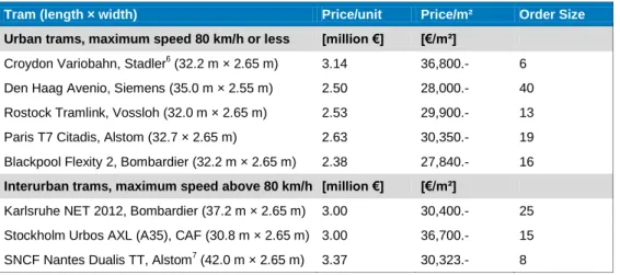
Tram (length × width) Price/unit Price/m² Order Size
Urban trams, maximum speed 80 km/h or less [million €] [€/m²]
Croydon Variobahn, Stadler6 (32.2 m × 2.65 m) 3.14 36,800.- 6 Den Haag Avenio, Siemens (35.0 m × 2.55 m) 2.50 28,000.- 40 Rostock Tramlink, Vossloh (32.0 m × 2.65 m) 2.53 29,900.- 13 Paris T7 Citadis, Alstom (32.7 × 2.65 m) 2.63 30,350.- 19 Blackpool Flexity 2, Bombardier (32.2 m × 2.65 m) 2.38 27,840.- 16
Interurban trams, maximum speed above 80 km/h [million €] [€/m²]
Karlsruhe NET 2012, Bombardier (37.2 m × 2.65 m) 3.00 30,400.- 25 Stockholm Urbos AXL (A35), CAF (30.8 m × 2.65 m) 3.00 36,700.- 15 SNCF Nantes Dualis TT, Alstom7 (42.0 m × 2.65 m) 3.37 30,323.- 8
The table above confirms that in general the “slower” (max. 80 km/h) rolling stock achieves lower prices than the available examples of trams with maxi-mum speed above 80 km/h.
The main differences of 100 km/h compared to a 70/80 km/h vehicle are:
Improved braking systems;
Higher powered propulsion system and different gearboxes, if accelera-tion is to be similar to the 70/80 km/h vehicle also at lower speeds;
Different bogies to achieve adequate running behaviour (comfort);
Dampers between body and bogie and also between different body sections;
Doors need to be able to withstand higher wind forces (mainly if vehicle pass each other at high speed);
Higher impact resistant windscreen;
Higher vehicle mass due to more requirements on crashworthiness. Trams operating at speeds above 100 km/h are very uncommon and no examples other than the North American vehicles operating at 65 mph (105 km/h) are known to the authors.
In Germany a clear tendency towards a maximum speed of 80 km/h can be made out, even for suburban or interurban tramway routes. This appears to be a fairly good compromise between travel speed and vehicle procurement and operating cost.
In North American light rail systems the general tendency appears to be to use a maximum speed of 105 km/h. However, those North American light rail systems are generally “heavier” in their appearance (more like conventional rail systems) than typical European tramways.
5 Source: Hondius (2010, 2011 and 2012a) – references [10], [11], [12]. 6
Nearly identical with Bergen Variobahn and taken from Bergen production process.
It also needs to be considered that a higher maximum speed and the use of a standard (non-switchable) transmission reduces the acceleration and decelera-tion of the vehicle. Higher maximum speed normally means lower acceleradecelera-tion performance (at the same degree of motorization).
It is a main goal of any public transport system to achieve attractive travel times for the passengers. In tramway systems this is usually achieved by the use of vehicles with high acceleration and deceleration capabilities.
In doing so it is important to achieve a balance between economy and technical adequacy in relation to the maximum vehicle speed, namely:
Economic:
Initial investment,
Energy consumption,
Operations and maintenance.
Technological:
Degree of motorisation,
Technical complexity, especially in terms of running behaviour, crashworthiness etc.
The following table provides a comparison of the major differences between urban and interurban operations and shows what is feasible from the technical point of view (note: this list shows the most common parameters of these two systems, however boundaries are fluid):
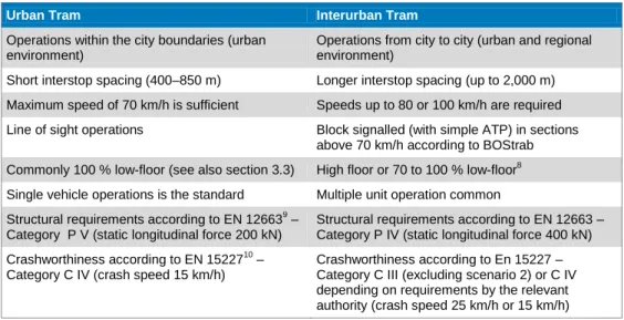
Table 2-2. Comparison of urban and interurban tram characteristics.
Urban Tram Interurban Tram
Operations within the city boundaries (urban environment)
Operations from city to city (urban and regional environment)
Short interstop spacing (400–850 m) Longer interstop spacing (up to 2,000 m) Maximum speed of 70 km/h is sufficient Speeds up to 80 or 100 km/h are required Line of sight operations Block signalled (with simple ATP) in sections
above 70 km/h according to BOStrab Commonly 100 % low-floor (see also section 3.3) High floor or 70 to 100 % low-floor8 Single vehicle operations is the standard Multiple unit operation common Structural requirements according to EN 126639 –
Category P V (static longitudinal force 200 kN)
Structural requirements according to EN 12663 – Category P IV (static longitudinal force 400 kN) Crashworthiness according to EN 1522710 –
Category C IV (crash speed 15 km/h)
Crashworthiness according to En 15227 – Category C III (excluding scenario 2) or C IV depending on requirements by the relevant authority (crash speed 25 km/h or 15 km/h)
8 70 to 100 % low floor is standard in vehicles with maximum speed 80 km/h. However, the combination
100 km/h and 100 % low floor is possible but an extremely complex and challenging requirement, which is likely to lead to both high investment and maintenance cost; and fewer manufacturers may be interested in bidding.
9
EN 12663 - Railway applications. Structural requirements of railway vehicle bodies. Reference [8].
2.2 Recommendations
For the initial, urban lines in Lund, Malmö and Helsingborg a vehicle with a maximum speed of 80 km/h should be procured.
The maximum speed for line of sight operated routes is 70 km/h in accordance with section 49 (§49) of BOStrab11.
For the future suburban and interurban routes, vehicles with 80 to 100 km/h maximum speed should be used. A decision between travel time gains and the economic impacts of the higher speeds needs to be made to determine whether identical (to those intended for the inner city lines) vehicles can be used. Impacts on travel times are described in appendix 1.
Even if the urban and interurban vehicles would be slightly different (i.e. if 100 km/h is chosen for the interurban routes), one vehicle type should be chosen based on the same vehicle platform from one manufacturer. This means that even if some components of the vehicles might differ due to the different speed requirements or due to different infrastructure requirements in the cities (e.g. slope in Helsingborg leading to a higher degree of motorization), most components would be equivalent and interchangeable.
This makes the complete fleet more economical and vehicles will have the same “look and feel” for the customer in all of the network.
The economic benefits of such a strategy are as follows:
Use of the same components and thus reduced spares requirements;
Higher order number provides economies of scale in the procurement process;
Reduced maintenance cost as staff will be familiar with whole vehicle family etc.;
Universal driver environment;
Reduced operational reserve, as fleet is more interchangeable. Two variants for this vehicle family exist:
1) If the maximum speed of 80 km/h is chosen for the interurban routes, the urban and interurban vehicles will be identical. In this case the trac-tion and braking equipment will be dimensioned for 80 km/h with the possibility to limit the maximum speed in the urban areas (and on line of sight sections) to 70 km/h within the traction control software. This ap-proach to utilize the same vehicle type for urban and interurban opera-tions is quite common in Germany (amongst others: Karlsruhe, Kassel, Chemnitz, Cologne/Bonn). This solution will also be the most beneficial in terms of safety, if a crash occurs between the vehicles in the network. Otherwise the different vehicle types will need to be designed such that
the consequences of a crash between the two types will be minimized – resulting most likely in additional mass12.
2) Should the maximum speed of 100 km/h be required for the inter-urban routes, the urban and interurban vehicles will differ signifi-cantly, even though the same vehicle family is utilized. In this case the gearboxes, brake resistors, suspension and dampers will have to be dif-ferent. The vehicle bodies, interiors, driver environment could be largely the same. Nevertheless this leads to an increased price (at least about 5 to 20 %, see page 9) compared to variant 1 above.
It is recommended to opt for operations with a maximum speed of 80 km/h. From the rolling stock perspective this is the economically and technically favourable solution.
12 If two vehicle types are procured on different occasions, i.e. the first procurement only includes 80 km/h
trams and later on a separate procurement is made for 100 km/h vehicles, the 80 km/h trams are not affected. However, the 100 km/h vehicles need to be designed in a way that makes the consequences of a possible crash with the 80 km/h trams “acceptable”.
3. Mechanical Aspects
3.1 Minimum Horizontal and Vertical Radii
In the document Handledning för spårvägsplanering i Skåne13 a horizontal minimal radius of 25 m and a minimum vertical radius of 625 m is identified for the trams (and as exceptional minimum for the infrastructure).
The value of 25 m for horizontal radii is also used in the BOStrab track alignment guidelines14 and should also be retained for the Skåne case.
In general it is advisable for infrastructure planning to use:
a “preferred minimum” value, which should be set at 40 m and an “absolute minimum” which should be set at 25 m.
It should be noted that a 40 m radius is an acceptable compromise between the space requirement and expected speed, wear and noise level. Between 40 and 25 m every metre counts and Spårvagnar i Skåne should develop a procedure to make sure that the design of every curve radius below 40 m needs their approval based on a local evaluation that larger radii are not possible. This means that planners should opt for at least 40 m radius throughout the network15.
Small radii mean a number of disadvantages:
Reduced operating speed;
Increased wear to wheel and track;
Higher noise level;
Larger dynamic kinematic envelope at that location.
It should also be noted that the above values are advisable for the route alignment itself. In stabling areas or depots where the space available is even more constraint, a minimum value as low as 22 m may be acceptable without restricting the available vehicle types.
Utilising the exceptional minimum value of 22 m in track design has the advantage of simplifying track design in very constrained areas. However, the disadvantages listed above will be even more severe.
The value of 625 m for vertical radii as a requirement for the trams is also used in the BOStrab track alignment guidelines14 and should also be retained for the
13 Reference [3]. 14
BOStrab-Trassierungsrichtlinien (2003), reference [6].
Skåne case. This is a value that should be possible to achieve for the types of trams which could be envisaged to operate in the Skåne region. However, the normal design value should be set higher to allow tolerances for subsidence and to be able to operate with an acceptable operating speed. The BOStrab track alignment guidelines states minimum 1000 m as a normal design value for the infrastructure16. This value is also used in the UITP (International Association of Public Transport) guidelines17.
The minimum radii have to be stated as a fixed requirement in the vehicle tendering documentation and it would be good practice to also provide the vehicle manufacturers with the design guidelines used on the system.
Hence, the vehicle should be required to be able to operate in vertical radii as small as 625 m and horizontal radii as small as 25 m (22 m in depots and stabling areas). However, the normal infrastructure design values are larger and should also be included in the future vehicle tendering document.
Recommendations
For horizontal radii it is proposed to use 40 m as a “preferred minimum” for the infrastructure and 25 m as an “absolute minimum” which the trams should be able to manage on the general route. Furthermore, 22 m may be used as an “absolute minimum” in depots and stabling areas.
A vertical minimum radius of 1000 m is proposed as the normal design value for the infrastructure and 625 m as a minimum for the vehicles.
All these values should be included in a future vehicle tendering document, with the minimum values being strict requirements (for the trams) and the preferred minimum values (for the infrastructure design) as information only.
16
In general, even larger radii are advisable, depending on the design speed.
3.2 Structural Concepts
This chapter provides an overview on the different structural concepts available for modern trams.
Vehicles with Pivoting Bogies
Figure 3-1. Vehicles with pivoting bogies – schematic. Source: Reference [5].
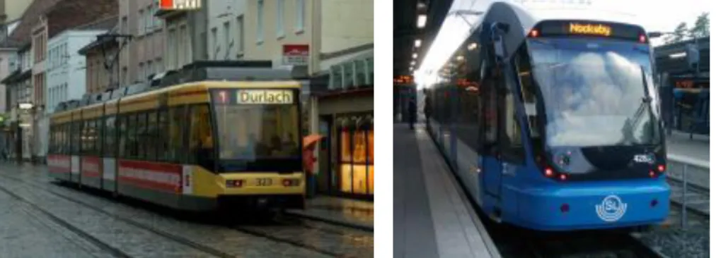
Examples for this type of vehicle are the Stockholm Urbos AXL by CAF and Karlsruhe NET 2012 by Vossloh, both of which have recently been procured.
Figure 3-2. Vehicles with pivoting bogies – examples. Source: CAF & Vossloh Kiepe.
General features of this kind of vehicle are:
Bogies with a large pivoting angle;
The maximum pivoting angle of the bogies is not reached in normal operations (i.e. operating conditions when very small radii are not en-countered), therefore the movement of the bogie is not restricted in nor-mal operations.
Vehicles with Short Body Segments
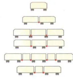
Figure 3-3. Vehicles with short body segments – schematic. Source: Reference [5].
Examples of this vehicle type are the GT6N operating in Munich (MAN) and the recently procured Avenio (Siemens) for Den Haag.
Figure 3-4. Vehicles with short body segments – examples. Source: TTK & Siemens.
General features of this kind of vehicle are:
Double chassis (bogies) with limited ability to pivot underneath the vehicle body;
While some movement of the chassis underneath the body is possible, it is common that this movement is restricted during normal operation (i.e. operating conditions when very small radii are not encountered).
Vehicles with Multiple Articulations
Figure 3-5. Vehicles with multiple articulations – schematic. Source: Reference [5].
Examples of this vehicle type are Variobahn operating in Bergen (Stadler) and the Citadis 302 (Alstom) for Mulhouse.
General features of this kind of vehicle are:
Double chassis (bogies) with very limited ability to pivot underneath the vehicle body;
As the pivoting angle is very limited, the movement of the chassis and vehicle body are nearly always directly connected. This leads to higher wheel-rail forces when negotiating horizontal radii.
Hybrid Solutions (e.g. Pivoting Bogies Combined with Multiple Articulations in the Central Area)
Examples for this are the GT6/8-70D/N as procured in Karlsruhe in the early nineties and the Stockholm A32.
Figure 3-7. Hybrid vehicles with conventional power bogies and multiple articulated centre sections – examples. Source: TTK.
General features of this kind of vehicle are:
In general these solutions result in a nominal 70 % low floor vehicle.
One disadvantage of these vehicles is the fact that the driver experiences the best ride characteristics of the vehicle, leading to a tendency to drive in a manner which leads to increased wear on the (unpowered) centre sections. On the other hand the solution allows the motor bogies used to be of the conventional, pivoting type and both wear and maintenance ef-fort on the motor bogies is therefore lower than on 100% low floor solu-tions.
Proprietary Solutions (Single Axle Chassis)
An example of a proprietary solution developed specifically for one public transport operator is the vehicle type ULF (Ultra-low-floor) developed for Vienna.
In this case no bogies or double but single axle chassis are used. This allows for a very low boarding level at the cost of a very complex and maintenance intensive vehicle.
The complexity of the driving arrangements with the single axle motors and the general fact that solutions are bespoke (i.e. tailor made only for this vehicle and operator) and experiences cannot be exchanged with other operators lead to low availability figures for such a fleet.
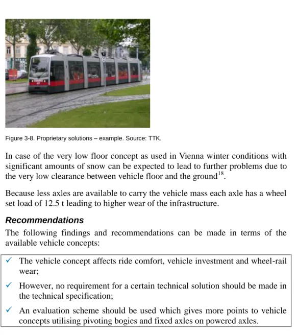
Figure 3-8. Proprietary solutions – example. Source: TTK.
In case of the very low floor concept as used in Vienna winter conditions with significant amounts of snow can be expected to lead to further problems due to the very low clearance between vehicle floor and the ground18.
Because less axles are available to carry the vehicle mass each axle has a wheel set load of 12.5 t leading to higher wear of the infrastructure.
Recommendations
The following findings and recommendations can be made in terms of the available vehicle concepts:
The vehicle concept affects ride comfort, vehicle investment and wheel-rail wear;
However, no requirement for a certain technical solution should be made in the technical specification;
An evaluation scheme should be used which gives more points to vehicle concepts utilising pivoting bogies and fixed axles on powered axles.
3.3 Low Floor Proportion
In general, there are two ways to achieve level boarding to a tram:
1) High floor vehicles and high platforms – Concerning the vehicle technology for urban and interurban services, this is the simplest solu-tion and has been chosen in cities including the Cologne/Bonn area, Manchester, Hannover, Bielefeld, Stuttgart and a number of systems in the USA, for example Los Angeles. However, the construction of high platforms is very challenging as they are difficult to integrate into the urban environment. For this reason many German cities now have two separate light rail systems, one low and one high floor, where the high floor system has been introduced earlier than the low floor one. Exam-ples include Frankfurt, Cologne and network in the Ruhr valley. It can be concluded that – with the exception of Manchester – no new high floor systems have been implemented in Europe.
2) Low floor vehicles and low platforms – Low floor vehicles which
operate as street running trams with a varying degree of separation from general road traffic utilizing platforms of 25 to 34 cm height can be well and relatively simply integrated into the urban environment. Such plat-form heights can also be utilized by the interurban or regional lines. The choice for a low floor system is therefore clearly within the current trend for tramways. The question remains whether rolling stock with a low floor proportion of 100 % or less should be utilized.
New urban tramways nowadays commonly use 100 % low floor rolling stock. This results from the development in the 90’s when the industry was of the opinion that bogies and fixed axles were no longer required. The development in France was driven mainly by design requirements and the long term costs (LCC) were in some cases less relevant. Today two conflicting trends can be seen: While the operators have a tendency to procure 70 % low floor designs due to the relating reduction in maintenance cost, the industry wants to (re-)sell their 100 % low floor designs, as these concepts generally are less costly in production.
Interurban or regional tramways use low floor rolling stock with a low floor proportion of 70 to 100 % of the vehicle length.
100 % low-floor solutions, especially when utilising multiple articulations, can lead to longer run times and higher wear, because their ride characteristics are not as smooth as those of a 70 % low-floor vehicle.
This experience has been made in Montpellier, where both 70 % low-floor and 100 % low-floor vehicles from the same manufacturer (Citadis by Alstom) are used. During an operational modelling project for the complete Montpellier tram network, TTK established through discussions with the operator that the 100 % low-floor versions have a one minute longer run time on this route than the 70 % low floor versions. This is due to the fact that the lateral accelerations on the multiple articulated vehicle as well as the experienced jerk rates are higher, leading to higher forces both at the wheel-rail level and in the vehicle body which in turn makes drivers operate this vehicle slower.
Figure 3-9. Montpellier 70 % low-floor vehicle, front bogie pivoting (left picture) and Montpellier 100 % low-floor vehicle, multiple articulations (right picture). Source: TTK.
Some of the comparative aspects of 100 % vs. 70 % low floor vehicles are listed below:
Table 3-1. Comparison of 100 % and 70 % low floor vehicles.
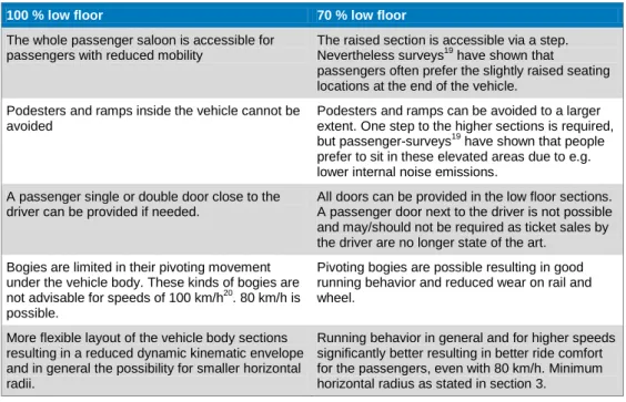
100 % low floor 70 % low floor
The whole passenger saloon is accessible for passengers with reduced mobility
The raised section is accessible via a step. Nevertheless surveys19 have shown that
passengers often prefer the slightly raised seating locations at the end of the vehicle.
Podesters and ramps inside the vehicle cannot be avoided
Podesters and ramps can be avoided to a larger extent. One step to the higher sections is required, but passenger-surveys19 have shown that people
prefer to sit in these elevated areas due to e.g. lower internal noise emissions.
A passenger single or double door close to the driver can be provided if needed.
All doors can be provided in the low floor sections. A passenger door next to the driver is not possible and may/should not be required as ticket sales by the driver are no longer state of the art.
Bogies are limited in their pivoting movement under the vehicle body. These kinds of bogies are not advisable for speeds of 100 km/h20. 80 km/h is possible.
Pivoting bogies are possible resulting in good running behavior and reduced wear on rail and wheel.
More flexible layout of the vehicle body sections resulting in a reduced dynamic kinematic envelope and in general the possibility for smaller horizontal radii.
Running behavior in general and for higher speeds significantly better resulting in better ride comfort for the passengers, even with 80 km/h. Minimum horizontal radius as stated in section 3.
The following figures show examples of floor level in a current 100 % low-floor tram design and a current 70 % low-low-floor design.
Figure 3-10. 100 % low-floor vehicle Bombardier Flexity 2 for Melbourne. The dashed line indicates floor level. Ramps inside the vehicle are needed. Source: Hondius (2011), reference [11], pro-cessed by Trivector.
Figure 3-11. 70 % low-floor vehicle Bombardier Flexity Classic for Kassel. The dashed line indicates floor level. Elevated floor at vehicle ends, but otherwise ramps can be avoided. Source: Hondius (2011), reference [11], processed by Trivector.
19Surveys carried out in Switzerland in the early 90’s. Experience confirmed also in Karlsruhe by the local
operator and TTK.
20
The combination 100 km/h and 100 % low floor is possible but an extremely complex and challenging requirement, which is likely to lead to both high investment and maintenance cost.
Accessible passenger doors can be provided throughout the vehicle on a 100 % low-floor tram. However, passenger doors close to the vehicle ends are not desirable as they can contribute to longer dwell times. Even if a double door could be provided, passengers at such doors can only move in one direction (away from the vehicle front/end). This in combination with the fact that late arriving passengers tend to use the outer doors first increases dwell times compared to a vehicle concept where doors are located such that passengers can move to the right and left within the vehicle.
In addition to this, it should be noted that all passenger doors can and should be provided in the low floor sections also in a 70 % low-floor tram, as shown above.
Recommendations
It is recommended to require a low floor proportion of a minimum of 70 % in the vehicle specification, to keep the possible vehicle types that can be offered as variable as possible.
Passenger doors close to the vehicle ends are not desirable, even on a 100 % low-floor vehicle, as they can contribute to longer dwell times. The framework for the future vehicles should be provided to the potential bidders by listing the relevant parameters that affect the low-floor proportion, such as:
Max. vehicle speed;
Minimal horizontal and vertical radii;
Dynamic kinematic envelope (DKE);
Running behaviour;
Acceptable wear behaviour for the wheel/rail interface;
Requirement for a passenger door next to the driver yes/no.
In addition to these parameters, the bidders should also be provided with the evaluation values for the different parameters, again adding clarity towards what kind of vehicle will be procured.
3.4 Bogies and Chassis
One of the most important requirements when discussing the future vehicle technology is the fact that the chosen solution, especially the bogies/chassis, primary and secondary suspension and resulting running behaviour, has to allow the required maximum vehicle speeds both safely but also economically in terms of initial procurement and maintenance. The chosen concept has an impact on the whole life cost.
The questions whether bogies or double chassis are utilized, whether fixed or rotating axles (or indeed stub axles) are used as well as the wheel diameter itself come into play when considering the maintenance and wear of the wheel
rail interface. This should be taken into account through the evaluation system used.
Pivoting Bogies and Fixed Chassis
In general, a pivoting bogie has the characteristic that the bogie has a high degree of freedom compared to the vehicle body it is carrying, meaning that the bogie can rotate into a radius before the vehicle body above has to follow. In contrast, a (fixed) chassis is more directly fixed to the vehicle body above, meaning that the vehicle body has to start rotating nearly at the same time as the first wheel set enters the radius. This leads to higher forces and therefore increased wear between rail and wheel when vehicles with chassis solutions are used.
Fixed Axles and Individually Rotating Wheels
A wheel with the correct geometry (e.g. adequate conicity) will show a tendency for self-steering towards the track centre if the left and right wheel are connected by an axle and are therefore rotating at the same speed.
Individually rotating wheels (i.e. wheels without “rotating axles”) experience higher wear rates as this self-steering ability of the wheel set is lost and such vehicles show a tendency for skewed operation where not all vehicle chassis operate exactly in parallel to the vehicle length axis on straight track.
Applications
In many cases 100 % low-floor designs in the past used a combination of individually rotating wheels and chassis with limited degrees of freedom against the vehicle body. Some late designs now use chassis with fixed axles and smaller wheels, however the degrees of freedom against the vehicle body are still limited.
Most 70 % low-floor designs feature motor bogies of conventional design, with fixed axles and a high degree of freedom against the vehicle body resulting in less wear on the motor bogies.
In terms of wear of the infrastructure, emphasis should be laid on the amount of unsprung mass of the concept. The unsprung mass is the mass of the suspen-sion, wheels and other components directly connected to them rather than supported by suspension. In the long run vehicles with high unsprung mass (for example due to missing primary suspension or hub motors) will lead to higher wear of the infrastructure.
It is for this reason that the question of maintainability also has to play an important role as evaluation criteria of the various rolling stock offers.
Recommendations
Vehicle concepts with pivoting bogies and fixed axles between the wheels (as a minimum on the powered axles) perform best in terms of long term maintenance cost based on the authors’ experience;
However, it is not recommended to make a specific requirement for a certain technical solution in the tender documentation.
The evaluation system should be geared such that vehicles which are expected to incur higher maintenance cost would receive lower scores. In addition to better scores for pivoting bogies and axles, the amount of un-sprung mass should also be considered.
3.5 Wheel Set Load
If no additional limiting factors such as limited loads over existing bridges or other structures would speak against this, the maximum acceptable static wheel set load should be set at 110 kN (equivalent to an wheel set mass, or axle mass, of 11 t).
The load of the vehicle should be spread as evenly as possible across all wheel sets.
The value of 110 kN is slightly higher than the value recommended in VDV recommendation 15021.
The following factors conflict with the general willingness in the industry to reduce the overall vehicle mass and lead to a tendency for “heavier” vehicles, resulting in the increased wheel set load recommendation compared to VDV 150:
The requirements within the European Standards EN 12663 concerning rail vehicle body structure and EN 15227 concerning crash worthiness;
Requirements for increased passenger comfort including air conditioning systems;
Redundancy of the auxiliary converters to improve operational reliabil-ity;
Provisions for multiple unit operation;
Increased standing space, mostly for multi-purpose areas;
Supercapacitors or other energy storage devices (further explained in chapter 4).
For these reasons it is recommended to include the following in the vehicle specifications:
A static wheel set load of 110 kN
With all seats occupied, where tipup-seats are considered standing space, i.e. remain unoccupied;
Assuming a load of 750 N per seated passenger;
Assuming a load of 5000 N per m² standing space;
With the remaining definitions in relation to the calculation of stand-ing space in accordance with “EN 12663 - Railway applications. Definition of vehicle reference masses”.
21 VDV Schrift 150 – Typempfehlungen Stadtbahnfahrzeuge (VDV recommendation 150 – recommendations of
The mentioned VDV recommendation 150 has been developed in 1995. In the meantime the requirements concerning the equipment and design of the vehicles have increased as mentioned above. It is for this reason that the original requirement of a static wheel set load of 100 kN can no longer be achieved in combination with an optimal proportion between vehicle length and the number of wheelsets.
On the other hand it is not advisable to use a static wheel set load of 120 kN in the vehicle specification, as this will inherently increase the wheel-rail wear and energy consumption.
Recommendations
Include a maximum static wheel set load of 110 kN in the specification.
Provide an evaluation system which will penalize but not exclude a proposal up to a maximum value of 120 kN and vice versa provide the possibility to achieve extra points for a reduced load.
During the development of the detailed vehicle specification, discussions will need to be carried out about what categories of EN 12663 “Railway applica-tions – Structural requirements of railway vehicle bodies”22 and EN 15227 “Railway applications – Crashworthiness requirements for railway vehicle bodies“23
should be used.
22
Reference [8].
4. Power Supply and Energy Storage Devices
4.1 Existing Technologies
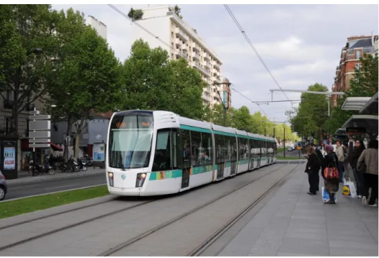
Overhead Power LinesPower supply from an overhead line (OHL) or catenary system (OCS) is a proven technology which has evolved over the past 100 years. With modern overhead line systems it is possible to achieve aesthetically pleasant and non-intrusive solutions in sensitive urban areas, as the picture below shows.
The ability to use regenerative braking and feed electrical power back to the overhead line is standard for all trams since many years. This allows a reduc-tion of propulsion energy consumpreduc-tion by about 30 %24. However, such a value can only be achieved if the urban 750 V DC power supply uses coupled feeding sections (i.e. feeding sections not isolated from each other) and operates a dense headway (e.g. time table frequency 5 min or less).
Figure 4-1. Tram and overhead line in Paris (source: Trivector).
For trams an electrically powered pantograph is standard.
The most important requirement in terms of the pantographs installed on the vehicles is that they are compatible with the installed zig-zag of the overhead line and the minimum and maximum reach required. Common values in accordance with BOStrab are overhead line heights between 4.2 m to 6.0 m.
The possible gradient relative to the running rails should be a minimum of 1:200.
In addition to using the regenerated braking energy within the 750 V DC system, some networks (e.g. Stuttgart) installed more sophisticated AC/DC-converters (utilizing so called H-bridges) in their substations which allow regenerated energy to be fed back from the 750 V DC side to the main grid. This arrangement needs an agreement from the energy provider to accept the (variable) power generated by the tramway system but allows for virtually all regenerated energy to be utilized without the use of energy storage devices. As this solution is quite expensive, it is mostly used in networks with significant gradients and thus potentially significant energy savings25.
For the Skåne applications, it should initially be investigated whether the energy supplier would accept energy to be fed back from the tramway system to the national grid. If this is the case, a cost analysis should be carried out to determine whether (under the prevailing conditions with steep slopes in Helsingborg and the long slope in Lund) this could be a cost efficient solution. Nevertheless, it is important to remember that this solution does not allow the operation over sections without overhead power line.
Supercapacitors
A supercapacitor (also referred to as ultracapacitor or supercap) is an electro-chemical capacitor with relatively high energy density. They are used for energy storage; the application in tramway systems is to store braking energy.
Energy Storage in the Substations
Tests with energy storage units in substations have been carried out in Germany (Cologne) by Siemens in the 1990s and proved not to be economically viable. Currently an EU research project called “Tickettokyoto”26
with the same topic is carried out in which the energy storage units in substations will be installed and tested in the cities of Bielefeld and Rotterdam. The results of this project are not yet known.
Energy Storage on the Vehicle
Compared to energy storage in the substation, the preference today is for storage directly on the tram, mainly because losses due to the resistance in the overhead power supply can be avoided. In recent years, supercapacitors have become the solution of choice for such an energy storage device.
Tests by Bombardier and Siemens have been carried out successfully.
First operational experiences with vehicles equipped with supercapacitors are also now available. Initial applications in serial production have been imple-mented in the past few years, with the following being either in operation or manufactured:
30 vehicles from Bombardier Transportation for RNV (Mann-heim/Heidelberg/Ludiwgshafen);
25
For instance, the Stuttgart tramway system includes a section on line U15 of about 4.5 km with an average
slope of 4–5 %.
15 vehicles from Solaris with electrical equipment from Vossloh Kiepe for Braunschweig;
25 vehicles from CAF for Sevilla (4) and Zaragoza (21);
13 vehicles from Vossloh for Rostock and
1 vehicle from Stadler for Geneva.
The energy savings with the supercapacitors are possible because even in a fully interconnected 750 V DC power supply not all braking energy can be recovered.
Figure 4-2. Energy flow on a vehicle using supercapacitor energy storage. Source: Bombardier Transportation, translation TTK.
Energy consumption in relation to the vehicle traction power can be reduced by 35 to 40 %27 when utilizing supercapacitor energy storage. This amount is a combination of the power generated back to the 750 V DC system and power stored in the supercapacitors.
It needs to be noted that the supercapacitors are expected to have a useable life of about 10–15 years and therefore would need to be replaced during the life span of the vehicle. They also increase the investment into the vehicles by approximately 3 %28.
The vehicle mass is increased by about 1,000 kg. Maintenance cost would be expected to increase only slightly, as the energy storage units are largely maintenance free if based on supercapacitor technology29.
Supercapacitors allow the vehicle to negotiate a short section at low speed without the need for overhead power supply.
27
Source: Vehicle Suppliers, TTK experience.
28
Based on TTK experience. The needed reinvestment after 10 to 15 years is yet unknown as no vehicles have reached that point yet. However, it is not expected to be more than the 3% again.
As an example, based on tests carried out by Siemens on the Sul do Tejo tramway, the following rough calculation can be made:
Vehicle mass (loaded): approx. 60 t
Two supercapacitor storage units with a useable energy content of about 1 to 1.2 kWh
Level ground
No intermediate stops
Auxiliary units at 20 kW
Speed 30 km/h.
Under these conditions it is estimated that it would be possible to bridge a section of about 100 to 150 m without overhead power under normal operating conditions.
These numbers need to be treated as estimates as they could vary significantly due to:
higher energy consumption on gradients;
higher energy consumption in tight radii curves;
higher energy consumption due to unexpected stops.
Great care would also need to be taken when determining the exact operational and recovery concept when running short sections without overhead line.
Traction Batteries
It is common to use NiMH or Lithium Ion batteries in combination with a step-up/step-down chopper or a battery loading device.
These storage units can achieve longer sections (between 0.5 and 2 km) at low speeds without the need for overhead power30.
With battery energy storage it is important to consider, that31:
The discharge current defines the required amount of cooling;
The discharge current also defines the life expectancy of the battery;
When discharging 10 % of the batteries nominal energy, this results in an available number of cycles at only 1/10 the number of a supercapacitor unit. This means that to achieve an adequate life expectancy of the bat-tery, good cooling, a low discharge current and a low number of cycles should be aimed at.
The battery capacity declines over time;
There are risks associated with the high energy density which is stored within the battery (e.g. fire risk, electric shock etc.)
Both Stadler and Siemens carried out research in this area. First operational experiences with vehicles equipped with traction batteries are now also available. Alstom supplied the fleet for the Nice tramway system equipped with
30
Based on TTK assessments.
traction batteries, allowing them to operate without overhead over a short section in the city centre.
Combination of Supercapacitors and Traction Battery
This combination provides the benefits of both types of energy storage:
Supercapacitors are an ideal energy storage unit for numerous, fast charging and discharging cycles but have limited energy density.
Traction batteries have a high energy density and thus are better
equipped to bridge short sections without overhead power, but the num-ber and speed of charging / discharging cycles is restricted.
Siemens carried out research and tests with such a combination on the Sul do Tejo tramway in Portugal.
Figure 4-3. Combination of supercapacitors and Traction Battery as used on the Sul do Tejo test. Source: Siemens.
In July 2012 Siemens received an order by Qatar Foundation to supply a 11.5 km long tramway for Qatar’s capital Doha. The system will not use overhead line equipment.
The Avenio trams to be used on this system will be equipped with supercapaci-tors and traction batteries and will be recharged from braking energy and with an overhead power bar provided at each tram stop.
As an example, based on tests carried out by Siemens on the Sul do Tejo tramway, the following rough calculation can be made for a system using both traction batteries and supercapacitors:
Vehicle mass (loaded): approx. 60 t;
One supercapacitor storage unit with a useable energy content of about 0.85 kWh;
One traction battery (18 kWh) with a useable energy content of about 1.8 kWh, i.e. only about 10% utilization to achieve an adequate expected battery life;
Level ground;
No intermediate stops;
Auxiliary units at 20 kW;
Under these conditions it is estimated that it would be possible to bridge a section of about 800 to 1000 m without overhead power32.
These numbers need to be treated as estimates as they could vary significantly due to:
The higher energy consumption on gradients;
The higher energy consumption in tight radii curves;
The higher energy consumption due to unexpected stops.
Great care would also need to be taken when determining the exact operational and recovery concept when running short sections without overhead line.
APS system from Alstom
The APS system provides energy to the vehicle via a third rail embedded between the running rails. It has been in operation in Bordeaux since 2003 on a network length of currently 11.4 km which is intended to be increased to 13.6 km (out of a total network length of 41 km).
Further orders after Bordeaux were received and realized from/in Reims, Angers and Orleans, with APS lengths of between 1 and 2 km each.
The system is now operating quite stable after significant initial teething problems.
In relation to a normal overhead line system, the APS system is about 3 to 4 times more expensive considering the initial investment only. On top of this, there is also a significantly higher maintenance requirement for this system33. The additional weight required on the trams themselves is negligible.
The efficiency of the power supply, i.e. losses due to the internal resistance of the system etc. is about the same as for a conventional overhead system.
Advantages of this system are34:
The system is already operational and past the initial steep learning curve;
The second series (APS II) of the system is now available, implementing learnings from the initial installations;
Has been approved for operation in France.
Disadvantages of this system are:
The system is very sensitive to outside climate conditions and is not tested in Northern climatic winter conditions (snow or ice)
32 Traction batteries are able to store more energy than supercapacitors, which on the other hand have a
higher power density. Therefore the possible distance without overhead power line is longer for the solution with only traction batteries than the solution with a combination of one supercapacitor-module with one battery-module (compared to two battery modules). The critical criteria is weight and basis for this assumption is the same weight for both solutions.
33
This has been confirmed by the local operator in Bordeaux during a number of visits.
34 Information based previous TTK projects for UK and Swiss operators in the years between 2008 and 2010.
TTK carried out interviews with Alstom, with the Bordeaux operator and made extensive site visits in the Bordeaux system.
The system is not approved for operation in Sweden (there has been no application);
The associated costs are very high (both initial investment and mainte-nance35);
There are durability issues if the system is implemented on sections also used by road traffic;
Regenerative braking is not possible due to the design of the APS;
The system is provided by one supplier only, leading to a non-competitive procurement of trams.
Figure 4-4. APS operating schematic. Source: Alstom.
Primove System from Bombardier
Similarly to the APS system, power is supplied from between the running rails to the vehicle. The major difference is that for Primove, a contactless inductive power transfer has been chosen utilizing a frequency of 20 kHz.
Tests under laboratory conditions on a test track in the Bombardier factory in Bautzen proved to be successful and in the meantime a trial track has been implemented in Augsburg to determine the system’s performance under more “real life” conditions.
The investment into Primove compared to a standard overhead line system is – according to Bombardier36 – currently 1:1.3 with the goal to move this to 1:1 in the future.
However maintenance required for the system is expected to be significantly higher than for a standard overhead system37.
The additional mass required on the vehicles is approximately 2 x 500 kg for the two pick-up units.
Bombardier quotes a power transmission efficiency of 90 to 92 % for the system36.
Advantages of this system are36:
The system is not sensitive to environmental conditions including snow;
According to current Bombardier estimates, the investment for this system would in time be similar to an overhead power supply system (currently approx. 30 % higher investment);
The system can be implemented in areas also used by road traffic;
The system can be combined with conventional track infrastructure including green track;
Reduced stray current problematic, as no current is returned through the running rails.
Disadvantages of this system are36:
The system has not been proven in normal operations;
Approval by authorities still in progress;
No regeneration into the system is possible. Bombardier therefore in-tends to combine this system with supercapacitor energy storage units on the vehicles;
The system works based on electromagnetic induction and therefore EMC is a potential problem requiring good mitigation measures;
Power from the national grid is transformed three times: 20 kV AC (or similar) to 750 V DC to 440 V AC to 750 V DC, each time with losses due to the transforming process;
The system is provided by one supplier only, leading to a non-competitive procurement of trams.
36
Hondius (2012b), reference [13].
For example about 25 %38 of the track infrastructure could be equipped with the Primove system to supply the energy which would be stored in the traction battery and the supercapacitors.
On the vehicle two Li-Ion traction batteries with about 50 kWh energy storage (about 1,000 kg each) could be utilized to provide the traction energy on the remaining 75 %38 of the network.
Figure 4-5. Primove operating schematic. Source: Bombardier.
4.2 Possible Mixtures of the Various Systems
The following mixture of power supply solutions exist already today:
Overhead power supply and supercapacitors;
Overhead power supply and traction batteries;
Overhead power supply on outer sections of the network and APS in the more sensitive urban areas.
Trials have been or are currently being carried out with the following combina-tions:
Overhead power supply plus a combination of traction batteries and supercapacitors;
Primove (most likely in combination with energy storage on the vehicle and possibly overhead power supply).
4.3 Economical Aspects
The economic viability of the various energy supply solutions discussed in the sections above has been assessed against the two likely applications in the Skåne region, i.e. urban and interurban operations.
For both solutions it can be said that the proven solution of overhead power supply is the most economical.
![Figure 3-5. Vehicles with multiple articulations – schematic. Source: Reference [5].](https://thumb-us.123doks.com/thumbv2/123dok_us/750369.2594794/23.892.182.715.952.1152/figure-vehicles-multiple-articulations-schematic-source-reference.webp)