Evaluation of the Traffic-Performance Characteristics of System-on-Chip
Communication Architectures
Kanishka Lahiri
Dept. of ECE
UC San Diego
[email protected]
Anand Raghunathan
NEC USA C&C Research Labs,
Princeton, NJ
[email protected]
Sujit Dey
Dept. of ECE
UC San Diego
[email protected]
Abstract
The emergence of several communication architectures for System-on-Chips provides designers with a variety of design al-ternatives. In addition, the need to customize the system archi-tecture for a specific application or domain, makes it critical for a designer to be aware of (and to evaluate) the trade-offs involved in selecting an optimal system-level communication architecture. While it is generally known that different communication archi-tectures may be better suited to serve the needs of different appli-cations, very little work has been done on quantitatively compar-ing and characterizcompar-ing their performance for different classes of on-chip communication traffic.
In this paper, we present a detailed analysis of the perfor-mance of various System-on-Chip communication architectures under different classes of on-chip communication traffic. We present high-level models of a few commonly used on-chip ar-chitectures, which take into account key architectural features, in-cluding their characteristic topologies and communication proto-cols. We present an efficient methodology to study the perfor-mance of each architecture, making use of (i) parameterized traf-fic generators, that help create a wide variety of on-chip nication traffic, and (ii) an implementation independent commu-nication interface abstraction, to enable plug-and-play evaluation of alternative communication architectures.
Our experiments show that the effectiveness of each architec-ture varies significantly, depending on the characteristics of the communication traffic (average communication rates of common architectures were seen to vary by as much as 409%). Addition-ally, they also demonstrate the criticality of judiciously selecting an on-chip communication architecture for a given application. We discuss the implications of our experiments, including the rel-ative strengths and weaknesses of the considered architectures, the classes of traffic that each is well suited to, and requirements for system design tools and methodologies in order to support ef-ficient communication architecture selection and customization.
1
Introduction
The System-on-Chip paradigm in electronic system design cre-ates new opportunities to improve several system design metrics, including performance, cost, size, power dissipation, and design turn-around time. In order to exploit these potential advantages to the fullest, it is essential to thoroughly explore the large design space made available by the System-on-Chip (SoC) approach. In particular, any SoC design methodology should adequately ad-dress two dimensions of system design. First, it is necessary to efficiently and optimally map an application’s computation re-quirements to a set of high-performance computing elements, like CPUs, DSPs, application specific cores, custom logic, etc. In this work we address a second, equally important, dimension of sys-tem design, that of selecting an optimal syssys-tem-level architecture
This work was supported by NEC USA Inc., and by the California Micro Program
that provides suitable mechanisms for high-speed on-chip com-munication. Increasingly complex systems, with heterogeneous (often predesigned) components implementing the application’s computation, result in increased volume and diversity of on-chip communication traffic. Hence, it is necessary to judiciously select a communication architecture that best suits (or is optimal for) the needs of communication traffic that is generated by the applica-tion. In addition to selecting a communication architecture from a variety of alternatives [1], it is necessary to customize (or tune) the selected architecture for the specific application or domain. Both these factors make it critical for a designer to be aware of, and to evaluate the trade-offs involved in the selection of an optimal system-level communication architecture.
Various competing communication architecture topologies and protocols have been developed and used commercially [2, 3, 4, 5], and it is known that different architectures may be better suited to serve the needs of different applications. For large systems with complex communications, ad hoc techniques that rely on a de-signer’s intuition to assess the characteristics of each application, and select an architecture to implement its communications, could result in a system with significantly sub-optimal performance. Recognizing this, there has been recent interest in developing fast and accurate system-level performance analysis and communica-tion architecture synthesis techniques [6, 7, 8, 9, 10, 11, 12, 13, 14]. However, these efforts do not provide any quantitative assess-ment or analysis of the relative merits and demerits of commonly available communication architectures for various classes of ap-plication traffic. The focus of this paper is to systematically and quantitatively explore the dependence between the performance of various communication architectures, and the characteristics of the traffic generated by an application which has been mapped to a set of system components. In addition, we identify parts of the application’s “communication traffic space” for which different communication architectures are well-suited.
1.1 Paper overview and contributions
In this paper, we present a detailed analysis of the performance of various commonly used SoC communication architectures, un-der several classes of on-chip communication traffic. The archi-tectures we consider in this paper include a static priority based shared system bus, a two-level hierarchical bus, a TDMA based architecture, and a ring based architecture. For our analysis, we developed high-level simulation models of each of the above com-munication architectures, taking into account their characteristic topologies, communication protocols, and various architectural parameters. We developed an efficient methodology to study the performance of the above architectures, based on the use of (i) pa-rameterized traffic generators to create a wide variety of on-chip communication traffic, and (ii) an implementation independent in-terface abstraction for inter-component communication, in order to minimize the effort involved in composing and analyzing the various candidate communication architectures.
Through experiments (based on simulation of the developed models of the architectures, components, and interfaces) we show that the effectiveness of each architecture varies significantly
with the characteristics of the communication traffic (performance metrics for common architectures were seen to vary by as much as 409%). We compare the performance of each architecture across a variety of on-chip traffic classes, as well as study the the relative ability of each architecture in being able to handle particular classes of traffic. Overall, we demonstrate the critical-ity of carefully selecting the on-chip communication architecture with the communication requirements and traffic characteristics of the application in mind. Our work motivates future research in system-level design, to develop techniques that methodically and efficiently explore the trade-offs that arise when selecting a high-performance communication architecture to satisfy an appli-cation’s communication requirements.
In the next section, we describe each of the architectures that we consider in this paper. In Section 3, we present the experimen-tal methodology, and in Section 4, we present the results of our experiments, including a discussion of the results and their im-plications. We conclude by commenting on the requirements for system design tools and methodologies to support efficient com-munication architecture selection and customization.
2
Modeling On-Chip Communication
Archi-tectures
In this section, we first introduce some concepts and terminol-ogy frequently used in connection with on-chip communication architectures. Next, we present high-level models of each com-munication architecture considered in this paper, highlighting the architectural features captured by each model.
2.1 Background
The various steps in designing a communication architecture for a System-on-chip include the following:
Selection of an appropriate topology: The topology typi-cally consists of several shared and dedicated communica-tion channels, to which the various SoC components are connected. Components that can initiate communications are called masters. Examples include CPUs, DSPs, DMA controllers, etc. Passive SoC components, or slaves, merely respond to transactions initiated by a master. (e.g., on-chip memories and peripherals). To enable communication be-tween master-slave pairs connected to different channels,
bridges are introduced where appropriate.
Selection of communication protocols: For each channel, the associated protocol specifies the exact manner in which communications across the channel take place, including handshaking conventions, burst mode transfer characteris-tics, endianness, etc. In addition, shared channels are em-powered with mechanisms to manage accesses from mul-tiple SoC masters. These include popular resource man-agement approaches such as round-robin access, priority
based selection, and time-division multiplexed access,
im-plemented in centralized or distributed bus arbiters. Specification of architectural parameters: These define
cer-tain properties of the channels and their associated protocols (e.g., bus widths, burst transfer size, priorities, etc). Mapping communications onto the architecture: The
vari-ous communications of the application are mapped to se-quences of channels (or paths) in the architecture by choos-ing appropriate component to channel assignments. Other than the topology, mapping, protocols and parameters of the communication architecture, another important factor that de-termines the performance of an application is the clock speed of each channel. For a given process technology, the clock frequency depends on the complexity of the interface logic, the placement of the various components, physical characteristics (capacitance val-ues) and routing of the wires.
An increasingly important issue in designing cores for use in HW/SW systems is the use of a consistent communication
inter-face to facilitate a design methodology where cores can be easily
integrated with other system components. Several on-chip bus standards are evolving to realize this goal, most notably that put forward by VSIA [1], and more recently, the Open Core Proto-col [15]. Using standard interfaces is advantageous because (i) it frees the core developer from having to make any assumptions about the system in which the core will be used, and (ii) facilitates the development of a variety of novel communication architec-tures not constrained by detailed interfacing requirements of each SoC component that it may potentially need to serve.
2.2 Static Priority Based Shared Bus
Arbiter Shared bus interface M1 interface M2 interface S1 interface M3 interface M4 interface S2 interface S3 interface S4 interface Parameters: BLK_TRAN_SIZE= 16, PRIORITY_M_1=3, PRIORITY_M_2=2, PRIORITY_M_3=1, PRIORITY_M_4=4, WIDTH=64, FREQ=66Mhz, . . .
Figure 1: Static priority based shared bus architecture The shared system bus with a static priority based arbitration protocol is one of the more commonly used on-chip bus architec-tures [3]. The bus (Figure 1) is a set of address, data and control lines that are shared by a set of masters that contend among them-selves for access to one or more slaves. In our model, the arbiter periodically examines accumulated requests from the four master interfaces, and grants bus access to the master that is of highest priority among all the requesting masters. The bus also supports a burst mode of data transfer, where the master negotiates with the arbiter to send or receive multiple words of data over the bus without incurring the overhead of handshaking for each word. Pa-rameters that characterize this architecture include the maximum size of a burst transfer, the width of the bus (bytes per word), its frequency of operation, and the address space associated with each slave interface.1
2.3 Hierarchical Bus
A hierarchical bus architecture consists of multiple busses, op-tionally interconnected by bridges. For our experiments, we mod-eled the architecture of Figure 2, a two level hierarchy connected by a bridge. A static priority based protocol (as described above) is implemented on each of the two busses. Each bus is connected to two master interfaces, two slave interfaces, an arbiter interface, and a bridge interface. The bridge interface needs to support both master and slave interfaces to carry out data transfers initiated by masters on either bus. It does this by activating its slave interface on the bus where the transaction is initiated, and its master inter-face on the bus where the transaction is targeted. A transaction going across the bridge involves a fair amount of overhead, and during the transfer, both busses remain inaccessible to other com-ponents. However, multiple word communications can proceed across the bridge in a pipelined manner.
Parameters for this architecture include those mentioned for the shared system bus and are associated with each of the two busses. Priorities determine the access rights of the bridge’s master in-terfaces, and an address space assignment characterizes its slave
1Note that the exact implementation of each architecture considered in this paper was chosen to be representative of, but is not necessarily identical to any commercial implementation. Also, variations and en-hancements (e.g., pre-emption, multi-threaded transactions, dynamic bus splitting, etc.), could be applied to any of the architectures, but were not considered in this paper for the sake of simplicity and fair comparison.
Bus 1 interface M1 interface M2 interface S1 interface S2 Arbiter1 interface Ma ster /Sla ve I/F BRI DG E Ma ster /Sla ve I/F Bus 2 interface M3 interface M4 interface S3 inter face S4 Bus 1 params: PRIORITY_M_1=1, PRIORITY_BRDG=3, FREQ=133MHZ,. . . Bus 2 params: PRIORITY_M_3=1, FREQ=133MHZ,. . . Arbiter inte rface
Figure 2: Hierarchical bus architecture
interfaces. In such an architecture, the key feature is that each bus is of shorter length, with fewer components contributing to the capacitive loading. Therefore, with other conditions remaining the same, each bus can be clocked at a higher rate than the single shared bus architecture described earlier. Also, transactions can proceed in parallel on the two busses.
2.4 Two-level TDMA based architecture
The third architecture we consider is based on time-division multiplexing. The topology we consider here is also a shared sys-tem bus, i.e., all components are connected to the same communi-cation channel. However, in this architecture, the components are provided access to the communication channel in an interleaved manner, using a two level arbitration protocol.
M1 M2 M3 M4 M3 M2 Current_slot N N N Y M1 M2 M3 M4 Timing wheel reservations Request map Old rr2 Newrr2’
(a) Timing wheel and sec-ond level round robin
G1 G2 G3 G1 D4 D1 D2 D3 D1 - D2 D1 G- G2 G1 G3 1 2 3 4 3 4 1 3 Resvn. Arbitrn. Data tx * *
(b) Pipelined word level ar-bitration and data transfer
Figure 3: Two-level TDMA based architecture
The first level of arbitration uses a timing wheel where each slot is statically reserved for a unique master (Figure 3(a)). In a single rotation of the wheel, a master which has reserved more than one slot is potentially granted access to the channel multiple times (e.g., M2and M3have reserved multiple slots). If the mas-ter inmas-terface associated with the current slot has an outstanding request, a single word transfer is granted, and the timing wheel is rotated by one slot.
To alleviate the problem of wasted slots (inherent in TDMA based approaches), a second level of arbitration is supported. The policy is to keep track of the last master interface to be granted access via the second level of arbitration, and issue a grant to the next requesting master in a round-robin fashion. In the example, the current slot is reserved for M1, but it has no data to commu-nicate. The second level increments a round-robin pointerrr2
from its current position at M2to the next outstanding request at
M4. In this manner, as long as there are outstanding requests, slots are not wasted. Additionally, arbitration is pipelined with word transfers as shown in Figure 3(b).
Architectural parameters include the number of slots in the tim-ing wheel, their reservations (this can be used to assign some components a guaranteed fraction of the channel bandwidth), the width and clock frequency of the channel.
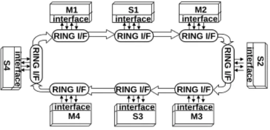
2.5 Ring Based Architecture
The last architecture we consider is a ring (Figure 4); based on a token passing protocol often used in local area networks [16].
RI NG I/F RING I/F RI NG I/F RING I/F
RING I/F RING I/F
RING I/F RING I/F
interface M1 in terface S2 interface M4 in terface S4 interface S3 interface M3 interface S1 interface M2
Figure 4: Ring based communication architecture Ring based architectures have also been used in high speed ATM switches [5], their high clock rates making them an attractive al-ternative to conventional bus architectures. The figure shows our model of a ring based architecture with 8 components attached to the ring through ring interfaces.
A special data word circulates on the ring which each interface can recognize as a token. A ring interface which receives a token is allowed to initiate a transaction. If the interface that receives the token has no pending request, then it forwards the token to its ring neighbor. If it does have a pending request, the ring interface captures the token, writes data into the ring, one word per ring cy-cle, (or reads data off it), for a fixed number of ring cycles. When the transaction is complete, it releases the token. For an arriving data word, a ring interface must examine the address associated with it and check if it belongs to the address space of any slave to which it may be connected.
The advantage of the ring based architecture is that the chan-nel is connected to all the components, but is point-to-point, and therefore can support much higher clock rates than the previously described architectures. An important parameter is the maximum token holding time, which bounds the maximum number of words a ring interface can send or receive each time it seizes the token.
3
Experimental Methodology
In this section, we present the experimental framework used to evaluate the considered communication architectures. We de-scribe a system test-bed, the use of parameterized traffic gener-ators, and an architecture independent communication interface. Finally, we present the performance metrics used in our study, and illustrate how they were obtained.
3.1 Test-Bed for Performance Evaluation
For our experiments we made use of the POLIS [17] HW/SW codesign environment. All components of the test-bed were modeled using Esterel and C, from which simulation models were generated using POLIS. Schematic capture and HW/SW co-simulation were performed using PTOLEMY [18].
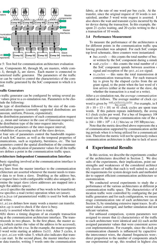
Figure 5 shows a system level test-bed to evaluate the perfor-mance of alternative communication architectures for different classes of application traffic. The test-bed was designed to pro-vide flexibility in two respects. First, the components should be capable of generating communication traffic with widely varying characteristics. This is made possible through the use of a set of configurable traffic generators. Second, the system should al-low plug-and-play of alternative communication architectures for a given configuration of the traffic generators (or class of appli-cation traffic). This is enabled by making use of an architecture independent communication interface. For our experiments, we chose a flexible test-bed which lends itself to systematic and con-venient experimentation instead of specific benchmark applica-tions, since such a test-bed provides better control over the char-acteristics of the generated communication traffic and is easily scalable.
The test-bed consists of 8 components exchanging variable quantities of data and control messages during the course of their
Comp M1 Comp M2 Comp M3
I/F I/F I/F I/F
Comp M4
Comp S1 Comp S2 Comp S3 Comp S4
I/F I/F I/F I/F
Traffic generators Communication Architecture Slave Interfaces Slave components Master components Master Interfaces
Figure 5: Test-bed for communication architecture evaluation execution. Components M1through M4are masters, while com-ponents S1 through S4 are slaves. Each master is connected to a parameterized traffic generator. The parameters of the traffic generator can be varied to control the characteristics of the com-munication traffic generated by the SoC component to which it is connected.
3.2 Traffic Generators
Each traffic generator can be configured by setting several pa-rameter values prior to a co-simulation run. Papa-rameters to be cho-sen include the following:
The type of distribution followed by the size of the com-munication requests (currently supported distributions are Gaussian, uniform, Poisson, exponential);
The distribution parameters of each communication request (e.g., mean and variance in the case of Gaussian requests); The distribution type of the inter-request intervals; Distribution parameters of the inter-request interval; Probabilities of accessing each of the slave devices. The first four sets of parameters control the bandwidth require-ments of each SoC master, as well as the temporal properties of its communications, such as regularity, burstiness, etc. The last set of parameters control the spatial distribution of the communi-cation traffic. A specificommuni-cation of parameter values for all the traffic generators defines a point in the communication traffic space. 3.3 Architecture Independent Communication Interface
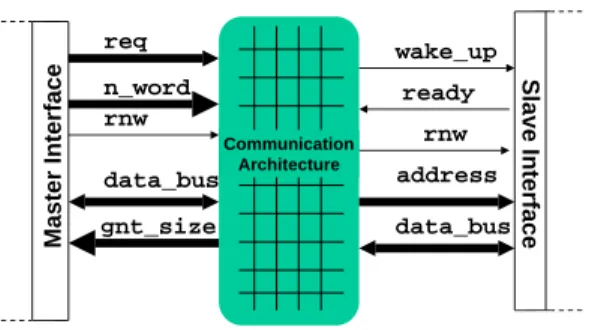
The basic signaling involved at the communication interface is shown in Figure 6(a).
reqlines from the master interface to the communication architecture are asserted whenever the master needs to trans-fer data to or from a slave. Doubling as the address bus, the request lines (with configurable width) also uniquely de-termine the target slave (slave addresses are mapped into a single flat address space).
n wordspecifies the number of bus words to be transferred.
rnwspecifies a read (write) operation when set (unset).
data bus(of parameterized width) is used for both reads
and writes.
gnt sizedefines how many words a master can transfer.
wake upis used to check if the slave is busy.
readyis asserted when the slave is ready.
Figure 6(b) shows a timing diagram of an example transaction executing at the communication architecture interface. The trans-action proceeds in two phases. In the first phase, the master as-sertsreq(which carries the value of the address to be accessed),
n word, and sets the bitrnw. In the example, the master requests for a 10 word write starting at address0x00. After 5 cycles, it receivesgnt sizewith value 5, which also indicates that trans-mission can start. In the second phase, the master interface exe-cutes the data transfer, writing 5 words onto the communication
fabric, at the rate of one word per bus cycle. At the end of this transfer, since the original request of 10 words is not completely satisfied, another 5 word write request is asserted. Figure 6(b) also shows the wait and transmit cycles incurred by the SoC mas-ter device during the transaction. In this example, the component spent 21 cycles waiting, and 20 cycles writing to the data bus for a transaction of 10 words.
3.4 Performance Measurement
To measure the performance of the architectures under study for different points in the communication traffic space, the fol-lowing procedure was adopted. For each SoC component in the top level schematic, three counters were instantiated:
bus words — this counts the total number of bus words read or written by the SoC component during a simulation run. wait cycles — this counts the total number of clock cycles
the SoC component spends between assertion of thereq
signal and reception of thegnt sizesignal.
tx cycles — this sums the total transmission delay for all communication transactions. For each transaction, the de-lay is given by the elapsed cycles from the arrival of the grant signal, to the point when the last word of the transac-tion arrives (either at the master or the slave, depending on whether the transaction is a read or a write).
After a co-simulation run, the average communication rate is cal-culated as follows. The average number of clock cycles per bus word is given bywait cycles+tx cycles
bus words . For example, in Figure 6(b), (8+10+13+10)or 41 clock cycles are spent transferring 10 words. If this pattern repeats indefinitely, the average delay is 4.1 clock cycles per word. For a bus of frequency 100 Mhz, and word size 64, the average communication rate of the architecture is(6410010
6
4:1)bits/sec or 195 Mbytes/sec.
Note that the metric described above represents the average rate of communication supported by communication architecture dur-ing periods when it is bedur-ing utilized for a communication transac-tion. Therefore the metric will not be spuriously reduced when the communication architecture is idle due to lack of access requests.
4
Experimental Results
In this section, we describe the experiments conducted on each of the architectures described in Section 2. We discuss the re-sults of the experiments, their implications, point out the relative strengths and weaknesses of the considered architectures, iden-tify classes of traffic that each is well suited to, and comment on the requirements for system design tools and methodologies in or-der to support efficient communication architecture selection and customization.
We conducted several experiments to study the comparative performance of the various architectures at different points in the communication traffic space. The characteristics of the commu-nication traffic were controlled by configuring the parameterized traffic generators and for each configuration, we measured the av-erage communication rate of each architecture (as described in Section 3), by simulating extensive input traces. In all cases, mea-sured values converged, and further simulation did not cause sig-nificant variation.
For unbiased comparison, system parameters were carefully assigned to ensure that (i) characteristics of the traffic presented to each architecture were identical and (ii) each architecture was assigned parameter values that were consistent across equivalent cost implementations. For example, since the clock period of the communication channels is influenced by capacitive loading of the interconnect wires, the channel frequencies were assigned in direct proportion to the number of components attached to it. In our experimental set up, this resulted in highest clock rates for
Master Interface req n_word rnw data_bus gnt_size Slave Interface data_bus wake_up ready address rnw Communication Architecture
(a) Master and slave signals
0x00 0x05 req 10 5 n_word write write rnw 5 5 gnt_size Data Data data_bus wait_cycles=8 tx_cycles=10 wait_cycles=13 tx_cycles=10
(b) Example of a write transaction at a master interface
Figure 6: Architecture independent communication interface the ring based architecture, proportionally lower rates for the
hi-erarchical architecture, and lowest rates for the TDMA and static priority based busses. The maximum block transfer size of the static priority and hierarchical architectures, the maximum token holding time of the ring based architecture, and the number of contiguously reserved slots for each component in the TDMA ar-chitecture were set to an identical value (10 bus words), while all the traffic generators were configured to generate communication traffic with similar characteristics.
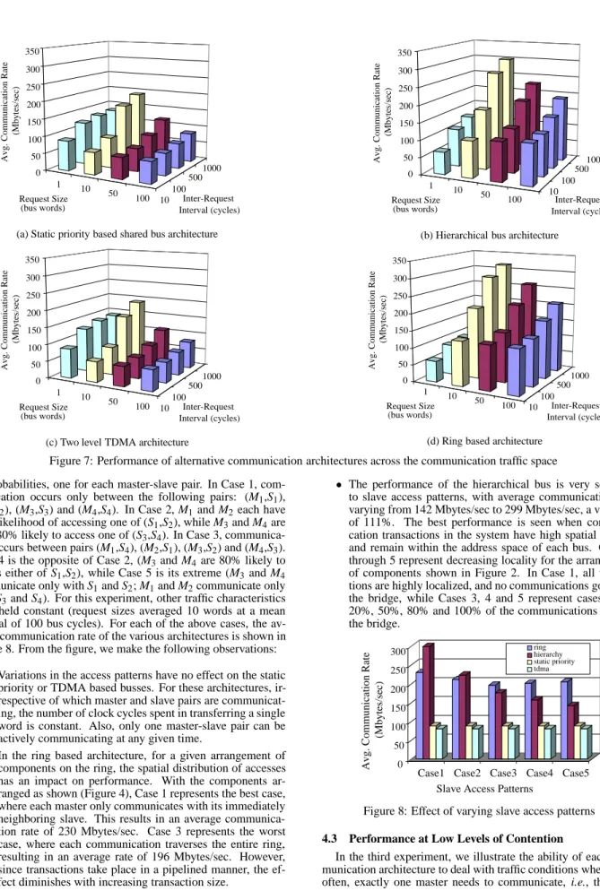
4.1 Effect of Request Sizes and Inter-Request Intervals The aim of the first set of experiments is to evaluate the perfor-mance characteristics of each architecture under communication traffic with a variety of average request sizes, and inter-request intervals. Figures 7(a)-(d) present results of these experiments. The X-Y plane in each figure denotes different points in the com-munication traffic space, with comcom-munication request sizes and intervals following Gaussian distributions. The X-axis denotes different values of the mean inter-request interval while the Y-axis denotes different values of the mean request size. In all cases, the standard deviation was 25% of the mean. The master-slave ac-cess probabilities were held constant, such that each master was equally likely to access each slave. The Z-axis denotes the av-erage communication rate delivered by the communication archi-tecture. From the graphs, we make the following observations: For each architecture, the average communication rate creases with increasing values of the mean inter-request in-terval. For example, in the ring based architecture, for requests with mean size 100, the communication rate im-proves from 133 Mbytes/sec (at intervals of 10 cycles) to 208 Mbytes/sec (at intervals of 1000 cycles). This is because larger intervals result in fewer conflicts (hence smaller wait-ing times) for access to shared communication resources. In most cases, with increasing mean request size, the
aver-age communication rate initially improves, and then deteri-orates. For example, in the case of the static priority based bus, for requests at mean intervals of 500 cycles, with creasing request size, the average communication rate in-creases from 131 Mbytes/sec to 168 Mbytes/sec, and even-tually decreases to 73 Mbytes/sec. This is due to a trade-off between the increased efficiency of transferring larger amounts of data (mechanisms such as burst transfers and pipelining help reduce arbitration overheads), versus the price of increased system load (larger transfers result in more conflicts, and hence increased waiting times). At a given point in the traffic space, different architectures
can have significantly different performance. For example, when the mean size is 50 words, and the mean interval is 500 cycles, the average rate of architectures (a) through (d) are 87, 192, 78, and 212 Mbytes/sec respectively.
The percentage variation in performance across different parts of the communication traffic space is significant, and differs from architecture to architecture. The ring and hi-erarchical bus architectures exhibit greater sensitivity to the characteristics of the communication traffic, (communica-tion rates vary by 409% and 355% respectively) than the static priority and TDMA based architectures (where rates vary by 208% and 216% respectively). Consequently, ar-chitectures with higher sensitivity should be chosen only if characteristics of the application’s traffic are likely to remain in parts of the space where performance is acceptable. No single architecture uniformly outperforms others. For
example, at request size 100, and interval size 100, the high-est average rate (140 Mbytes/sec), is provided by the ring based architecture, while at size 1, and interval 100, it is provided by the TDMA architecture (129 Mbytes/sec). The ring based architecture performs well for most parts of
the space, in fact, providing upto 316 Mbytes/sec for cer-tain types of traffic. This is because the superior bandwidth of each link in the ring permits high-speed pipelined data transfers. However, for small request sizes, the dominating factor in each transaction is the latency of communicating with a remote slave. In such cases, the total transmission delay (including interface overheads) is highly dependent on the number of ring segments each word has to traverse. The observed communication rates (under uniformly distributed slave accesses) were as low as 62 Mbytes/sec.
The hierarchical bus also exhibits comparatively high av-erage communication rates (upto 300 Mbytes/sec). This is due to the higher degree of parallelism inherent in the ar-chitecture, and the high bandwidth of each bus. However, here too, the advantages are limited when the requests are small and have uniformly distributed addresses (observed communication rates were as low as 65 Mbytes/sec). The main factor which contributes to these low rates is the high latency of communications involving both busses, each of which incur two bus transmission delays, and extra over-head due to additional handshaking at the bridge. At request sizes of 10, communications across the bridge take place in a pipelined manner, effectively reducing the impact of these high latencies. However, this benefit is limited for larger re-quest sizes, because during each bridge transaction, both the busses remain inaccessible to other system components for longer periods of time, resulting in lower average communi-cation rates.
4.2 Effect of Spatial Locality of Communication Traffic The next experiment we carried out was to examine the effect of varying the slave access probabilities for each master device. Note that changing these probabilities directly affects the spatial locality of the communication traffic. Here we chose 5 cases of probability values, where each case consists of a specification of
100 50 10 1 0 50 100 150 200 250 300 350 Avg. Communication R ate (Mbytes/sec) Inter-Request Interval (cycles) Request Size (bus words) 10 500 100 1000
(a) Static priority based shared bus architecture
100 50 10 1 0 50 100 150 200 250 300 350 Avg. Communication R ate (M bytes /sec) Inter-Request Interval (cycles) Request Size (bus words) 10 500 100 1000
(b) Hierarchical bus architecture
100 50 10 1 0 50 100 150 200 250 300 350 Avg. Communication R ate (M bytes /sec) Inter-Request Interval (cycles) Request Size (bus words) 10 500 100 1000
(c) Two level TDMA architecture
100 50 10 1 0 50 100 150 200 250 300 350 Avg. Communication R ate (Mbytes/sec) Inter-Request Interval (cycles) Request Size (bus words) 10 500 100 1000
(d) Ring based architecture
Figure 7: Performance of alternative communication architectures across the communication traffic space 16 probabilities, one for each master-slave pair. In Case 1,
com-munication occurs only between the following pairs: (M1,S1), (M2,S2), (M3,S3) and (M4,S4). In Case 2, M1and M2 each have 80% likelihood of accessing one of (S1,S2), while M3and M4are each 80% likely to access one of (S3,S4). In Case 3, communica-tion occurs between pairs (M1,S4), (M2,S1), (M3,S2) and (M4,S3). Case 4 is the opposite of Case 2, (M3and M4 are 80% likely to access either of S1,S2), while Case 5 is its extreme (M3and M4 communicate only with S1and S2; M1and M2communicate only with S3and S4). For this experiment, other traffic characteristics were held constant (request sizes averaged 10 words at a mean interval of 100 bus cycles). For each of the above cases, the av-erage communication rate of the various architectures is shown in Figure 8. From the figure, we make the following observations:
Variations in the access patterns have no effect on the static priority or TDMA based busses. For these architectures, ir-respective of which master and slave pairs are communicat-ing, the number of clock cycles spent in transferring a single word is constant. Also, only one master-slave pair can be actively communicating at any given time.
In the ring based architecture, for a given arrangement of components on the ring, the spatial distribution of accesses has an impact on performance. With the components ar-ranged as shown (Figure 4), Case 1 represents the best case, where each master only communicates with its immediately neighboring slave. This results in an average communica-tion rate of 230 Mbytes/sec. Case 3 represents the worst case, where each communication traverses the entire ring, resulting in an average rate of 196 Mbytes/sec. However, since transactions take place in a pipelined manner, the ef-fect diminishes with increasing transaction size.
The performance of the hierarchical bus is very sensitive to slave access patterns, with average communication rate varying from 142 Mbytes/sec to 299 Mbytes/sec, a variation of 111%. The best performance is seen when communi-cation transactions in the system have high spatial locality and remain within the address space of each bus. Cases 1 through 5 represent decreasing locality for the arrangement of components shown in Figure 2. In Case 1, all transac-tions are highly localized, and no communicatransac-tions go across the bridge, while Cases 3, 4 and 5 represent cases where 20%, 50%, 80% and 100% of the communications involve the bridge. 0 50 100 150 200 250 300 Avg. C ommuni cat ion Rate (M byte s/se c)
Case1 Case2 Case3 Case4 Case5 Slave Access Patterns
ring hierarchy static priority tdma
Figure 8: Effect of varying slave access patterns 4.3 Performance at Low Levels of Contention
In the third experiment, we illustrate the ability of each com-munication architecture to deal with traffic conditions where most often, exactly one master needs to communicate, i.e., there are
very few conflicts for access to the communication architecture. We modeled such conditions by shutting down all the traffic gen-erators except one, and had it generate single word requests at short intervals. The results (Figure 9) indicate the following: (a) the static priority bus performs the best, providing the highest av-erage communication rate of 143 Mbytes/sec; (b) the hierarchical bus at 114 Mbytes/sec is 25% poorer. The reasons for this are (i) the potential benefit of parallelism offered by this architecture is not utilized by this type of traffic, and (ii) small communication requests equally distributed throughout the address space have significant latencies owing to frequent transactions that involve the bridge; (c) The TDMA based architecture provides poorer per-formance than the previous two, because many of the TDMA slots are assigned via the second level of arbitration (Section 2) since only one component accesses the bus. The extra cycles spent in ar-bitration results in an average rate of 110 Mbytes/sec, 29% poorer performance than the static priority based bus; (d) The ring based architecture provides the poor performance, because each time the active component releases the token, it must wait till the token tra-verses the entire ring before it can start using the channel again. The observed rate (81 Mbytes/sec) is 75% lower than that offered by the static priority based single shared bus.
0 20 40 60 80 100 120 140 160 Average C ommunication Rate (Mbytes/sec)
ring hierarchical static priority tdma
Figure 9: Performance comparison at low contention 4.4 Summary
In summary, it is very important to carefully assess the prop-erties of the communication traffic generated by an applica-tion while selecting a communicaapplica-tion architecture. An incorrect choice may result in significantly sub-optimal performance. For instance, choosing a ring based architecture for a system where most of the time the only active master is a processor core, could severely impede the application’s performance. Depending on the characteristics of the on-chip communication traffic, the choice of the the best communication architecture could vary, since there is no architecture that is optimal for all types of traffic. The above experiments suggest that one needs to be cautious when choosing a “traffic sensitive” communication architecture (such as a hierar-chical bus), to ensure compatibility of the communication traffic and the chosen architecture.
Our experiments demonstrate that there is a crucial need for system design tools and methodologies to support methodical and careful exploration of available choices, when selecting a com-munication architecture for an application with specific commu-nication traffic characteristics. Current design methodologies (in-cluding the one used for our experiments), are far from being able to provide such frameworks. Simulation based methods, though accurate, can be very expensive and time consuming, hence are infeasible for achieving the above goals when dealing with large, complex systems. Our experiments motivate a new research di-rection whose aim is to develop techniques to extract an applica-tion’s on-chip communication traffic characteristics, and then ef-ficiently and accurately predict performance of the system under candidate communication architectures. A step further would be to develop techniques that automatically suggest to the designer
the most suitable communication architecture for the target appli-cation. Tools such as these will aid a designer in achieving better optimized solutions for high-performance systems, while at the same time help reduce design turn-around-time.
5
Conclusions and Future Work
In this work, we evaluated the performance characteristics of several communication architectures under different classes of communication traffic. We demonstrated the importance of se-lecting an architecture that is well suited to the characteristics of the traffic generated by an application. We presented our use of high-level models of commonly used communication architec-tures, and a framework that aided systematic and efficient com-parison of their performance. Our conclusion is that the optimal-ity of a communication architecture is highly dependent on spe-cific properties of the traffic generated by the application. Con-sequently their selection and design should be aided by auto-mated, systematic analysis of the system’s communication behav-ior. Since current system design methodologies are not geared towards providing a designer with such feedback, we plan to ad-dress this gap in the future by (i) developing models to exten-sively capture the characteristics of on-chip communication traf-fic, and (ii) developing efficient analysis and exploration tools that use such characterizations to guide the design of communication architectures that are highly optimized for a target application.
References
[1] “On chip bus attributes specification 1 OCB 1 1.0, On-chip bus DWG.” http://www.vsi.org/library/specs/summary.htm.
[2] “IBM On-chip CoreConnect Bus Architecture.” http://www.chips.ibm.com/products/coreconnect/index.html. [3] “Peripheral Interconnect Bus Architecture.” http://www.omimo.be. [4] “Sonics Inc.” http://www.sonicsinc.com.
[5] J. Turner and N. Yamanaka, “Architectural choices in large scale ATM switches,” IEICE Trans. on Communications, vol. E-81B, Feb. 1998.
[6] J. A. Rowson and A. Sangiovanni-Vincentelli, “Interface Based De-sign ,” in Proc. DeDe-sign Automation Conf., pp. 178–183, June 1997. [7] K. Hines and G. Borriello, “Optimizing Communication in
em-bedded system cosimulation ,” in Proc. International Workshop on
Hardware/Software Codesign, pp. 121–125, Mar. 1997.
[8] K. Lahiri, A. Raghunathan, and S. Dey, “Fast performance analysis of bus-based system-on-chip communication architectures,” in Proc.
Int. Conf. Computer-Aided Design, pp. 566–572, Nov. 1999.
[9] K. Lahiri, A. Raghunathan, and S. Dey, “Performance analysis of systems with multi-channel communication architectures,” in Proc.
Int. Conf. VLSI Design, pp. 530–537, Jan. 2000.
[10] P. Knudsen and J. Madsen, “Integrating communication protocol se-lection with partitioning in hardware/software codesign ,” in Proc.
Int. Symp. System Level Synthesis, pp. 111–116, Dec. 1998.
[11] M. Gasteier and M. Glesner, “Bus-based communication synthesis on system level ,” in ACM Trans. Design Automation Electronic
Sys-tems, pp. 1–11, Jan. 1999.
[12] T. Yen and W. Wolf, “Communication synthesis for distributed embedded systems ,” in Proc. Int. Conf. Computer-Aided Design, pp. 288–294, Nov. 1995.
[13] J. Daveau, T. B. Ismail, and A. A. Jerraya, “Synthesis of system-level communication by an allocation based approach ,” in Proc.
Int. Symp. System Level Synthesis, pp. 150–155, Sept. 1995.
[14] S. Dey and S. Bommu, “Performance analysis of a system of com-munication processes,” in Proc. Int. Conf. Computer-Aided Design, pp. 590–597, Nov. 1997.
[15] “Open Core Protocol Specification version 1.0.” http://www.sonicsinc.com, Oct. 1999.
[16] A. S. Tanenbaum, Computer Networks. Englewood Cliffs, N.J.: Prentice Hall, 1989.
[17] F. Balarin, et al, Hardware-software Co-Design of Embedded
Sys-tems: The POLIS Approach. Kluwer Academic Publishers, Norwell,
MA, 1997.
[18] J. Buck, et al, “Ptolemy: A framework for simulating and pro-totyping heterogeneous systems,” International Journal on
Com-puter Simulation, Special Issue on Simulation Software Manage-ment, vol. 4, pp. 155–182, Apr. 1994.