Verifying Hybrid Systems Modeled as Timed
Automata: A Case Study
?Presented atHART'97, Grenoble,France,March26-28, 1997
Myla Archer and Constance Heitmeyer
Code 5546, Naval Research Laboratory, Washington, DC 20375
farcher, [email protected]
Abstract. Verifying properties of hybrid systems can be highly
com-plex. To reduce the eort required to produce a correct proof, the use of mechanical verication techniques is promising. Recently, we extended a mechanical verication system, originally developed to reason about deterministic real-time automata, to verify properties of hybrid systems. To evaluate our approach, we applied our extended proof system to a solution, based on the Lynch-Vaandrager timed automata model, of the Steam Boiler Controller problem, a hybrid systems benchmark. This pa-per reviews our mechanical verication system, which builds on SRI's Prototype Verication System (PVS), and describes the features we added to handle hybrid systems. It also discusses some errors we de-tected in applying our system to the benchmark problem. We conclude with a summary of insights we acquired in using our system to specify and verify hybrid systems.
1 Introduction
Researchers have proposed many innovative formal methods for developing real-time systems [9]. Such methods can give system developers and customers greater condence that real-time systems satisfy their requirements, especially their crit-ical requirements. However, applying formal methods to practcrit-ical systems re-quires the solution of several challenging problems, e.g., how to make formal descriptions and formal proofs understandable to developers and how to design software tools in support of formal methods that are usable by developers.
We are building a mechanized system for specifying and reasoning about real-time systems that is designed to address these challenging problems. Our approach is to build formal reasoning tools that are customized for specifying and verifying systems represented in terms of a specic mathematical model. In [2], we describe how we are using the mechanical proof system PVS [18, 19] to support formal specication and verication of systems modeled as Lynch-Vaandrager timed automata [15, 14]. Reference [2] also presents the results of a case study in which we applied our method to prove invariant properties of a solution to the Generalized Railroad Crossing (GRC) problem [7].
Our system provides mechanical assistance that allows humans to specify and reason about real-time systems in a direct manner. To specify a particular timed automaton, the user lls in a template provided by our system. Then, he or she uses our system, a version of PVS augmented with a set of specialized PVS proof strategies, to verify properties of the automaton. Use of our system for
? This work is funded by the Oce of Naval Research. URLs for the authors are
specication and verication is usually quite straightforward because our system provides both a structure and a set of specialized theories useful in constructing timed automata models and proving properties about them. By focusing on a particular mathematical model|the timed automata model|our system allows a user to reason within a specialized mathematical framework. The user need not master the base logic and the complete user interface of the underlying proof system, PVS.
The results of our initial study proved encouraging. All of the hand proofs of invariant properties in the GRC solution were translated into corresponding PVS proofs with a very similar structure. Moreover, most of the PVS proofs could be done using our specialized strategies alone. Neither the time required to enter the specications using our template nor the time required to check the proofs of state invariants was excessive.
While our initial study only involved deterministic automata, we recently demonstrated that the same approach could be applied to hybrid automata, where the eects of time passage and other events can be nondeterministic. To study the utility of our proof techniques for verifying hybrid systems, we applied them to a solution of the Steam Boiler Controller problem described in [12]. In verifying this application, we investigated the following issues:
{
How should nondeterminism be modeled?{
Is it practical to use an automatic theorem prover to reason about nonlinear real arithmetic?{
Can the timed automata template and proof strategies developed in our earlier case study be extended to handle the more general problem of hybrid automata?{
How suitable is PVS for verifying properties of hybrid systems?In verifying the solution in [12], we detected several errors. While most of these errors are minor and easily xed, at least two of the errors are errors in reasoning, and their correction is nontrivial.
Like other approaches to verifying real-time systems, such as SMV [16, 5],
HyTech [10], and COSPAN [11], our approach is based on a formal automata
model. Moreover, like these other approaches, our methods can be used to prove properties of particular automata and, like COSPAN, to prove simulations be-tween automata.1However, our approach is dierent from other approaches in
several ways. First, the properties we prove are expressed in a standard logic with universal and existential quantication. This is in contrast to most other approaches, where the properties to be proved are expressed either in a temporal logic, such as CTL orIctl, or in terms of automata. By using standard notations
and standard logics and by providing templates for developing specications, we largely eliminate the need for the special notations, logics, etc., required by other verication systems. Second, unlike other automata-based methods, the genera-tion of proofs in our method is not completely automatic. Rather, our method uses a mechanical proof system to check the validity of hand proofs that use deductive reasoning.
1We have designed support for verifying simulation proofs, but implementation of this
Interaction with an automatic proof system does demand a higher level of sophistication from the user. But by supporting reasoning about automata at a high level of abstraction, we can prove more powerful results than is possible with tools requiring more concrete descriptions of automata. Moreover, our approach avoids the state explosion problem inherent in other automata-based approaches and also provides considerable feedback when an error is detected. Such feedback is extremely useful in correcting errors.
Section 2 reviews the timed automata model, PVS, and the template and tools we developed in our earlier verication of the GRC. Section 3 introduces the Steam Boiler Controller problem, presents the main hybrid automaton speci-ed in [12], and discusses the techniques we usspeci-ed to adapt our template to proving properties of hybrid automata. Section 4 presents our major results|the errors we detected in applying our system to the Boiler Controller problem and the time and eort we needed to adapt and apply our methods. Section 5 presents an example of a hand proof and the corresponding PVS proof for a state invari-ant whose proof involves both nondeterminism and nonlinear real arithmetic. Section 6 presents some conclusions about the usefulness of our methods for verifying hybrid automata.
2 Background
2.1 The Timed Automata Model
The formal model used in the specication of the Boiler Controller problem and its solution [12] represents both the computer system controller and its envi-ronment as Lynch-Vaandrager timed automata. A timed automaton is a very general automaton, i.e., a labeled transition system. It need not be nite-state: for example, the state can contain real-valued information, such as the current time, the boiler's water level, and the boiler's steam rate. This makes timed automata suitable for modeling not only computer systems but also real-world quantities, such as water levels and steam rates. The timed automata model describes a system as a set of timed automata, interacting by means of common actions. In the Boiler Controller solution presented in [12], separate timed au-tomata represent the boiler and the controller; the common actions are sensors reporting the water level, steam rate, and number of active pumps in the boiler, and actuators controlling whether to stop the boiler and when the next sensor action is scheduled. The denition of timed automata below, which is based on the denitions in [8, 7], was used in our earlier case study [2]. It is a special case of Lynch-Vaandrager timed automata, which requires the next-state relation, steps(A), to be a function. How to modify the denition to handle the
nonde-terminism inherent in hybrid automata was one of the issues addressed in our current study.
Atimed automatonAconsists of ve components: { states(A), a (nite or innite) set of states.
{ start(A)states(A), a nonempty (nite or innite) set of start states. { A mappingnowfromstates(A) toR
0, the non-negative real numbers.
{ acts(A), a set of actions (or events), which include special time-passage actions (t), wheretis a positive real number, andnon-time-passageactions, classied
asinputandoutputactions.
{ steps(A) : states(A)acts(A) ! states(A), a partial function that denes the
2.2 PVS
PVS (Prototype Verication System) [19] is a specication and verication en-vironment developed by SRI International's Computer Science Laboratory. In contrast to other widely used proof systems, such as HOL [6] and the Boyer-Moore theorem prover [4], PVS supports both a highly expressive specication language and an interactive theorem prover in which most low-level proof steps are automated. The system provides a specication language, a parser, a type checker, and an interactive proof checker. The PVS specication language is based on a richly typed higher-order logic that permits a type checker to catch a number of semantic errors in specications. The PVS prover provides a set of inference steps that can be used to reduce a proof goal to simpler subgoals that can be discharged automatically by the primitive proof steps of the prover. The primitive proof steps incorporate arithmetic and equality decision procedures, automatic rewriting, and BDD-based boolean simplication.
In addition to primitive proof steps, PVS supports more complex proof steps called strategies, which can be invoked just like any other proof step in PVS. Strategies may be dened using primitive proof steps, applicative Lisp code, and other strategies, and may be built-in or user-dened.
2.3 A Template For Specifying Timed Automata in PVS
Our template for specifying Lynch-Vaandrager timed automata provides a stan-dard organization for an automaton. To dene a timed automaton, the user supplies the following six components:
{ declarations of the non-time actions,
{ a type for the \basic state" (usually a record type) representing the state variables, { any arbitrary state predicate that restricts the set of states (the default istrue), { the preconditions for all transitions,
{ the eects of all transitions, and { the set of start states.
In addition, the user may optionally supply
{ declarations of important constants,
{ an axiom listing any relations assumed among the constants, and { any additional declarations or axioms desired.
To support mechanical reasoning about timed automata using proof steps that mimic human proof steps, we also provide an appropriate set of PVS strategies, based on a set of standard theories and certain template conventions. For exam-ple, the induction strategy, which is used to prove state invariants, is based on a standard automaton theory called
machine
. To reason about the arithmetic of time, we have developed a special theory calledtime thy
and an associatedsimplication strategy called
TIME ETC SIMP
for time values that can beeither non-negative real values or 1.
3 Specifying and Reasoning About Hybrid Automata
Like others, we use the term hybrid automaton to describe a state machine which has both continuous and discrete components. Since hybrid automata are used to model physical systems controlled by a discrete computer system, the laws of physics aect their behavior. Because changes in measurable properties of the physical systems depend on environmental factors, automata models of these systems typically have some nondeterministic transitions. Thus, hybridautomata dier from deterministic, discrete automata in two major ways: their behavior is nondeterministic and reasoning about their transitions often leads to complex computations involving nonlinear real arithmetic.
Strictly speaking, the automata in our case study of the GRC problem [2] are hybrid automata by the above denition. However, their description involved neither nondeterminism nor nonlinear arithmetic. For the example in the current case study, it was necessary to extend our previous methods to handle both of these features.
3.1 Reasoning About Hybrid Automata
Handling Nondeterminism.
To specify and to reason about nondeterministic automata using an automated theorem prover, one needs to describe the nonde-terministic transitions. An obvious approach is to represent the transitions as a relation. In an initial experiment, we encoded the transitions in a deterministic automaton from our initial study [2] as a relation and redid the proofs of state invariants up to and including the Safety Property, the major theorem. Because the selected timed automaton is deterministic, the transition relation was ex-pressed as an equality between the result state and a case expression involving the action and the initial state. The new versions of the state invariant proofs were quite similar to the corresponding proofs in [2] , except for two important dierences. First, they took about twice as long to execute. Second, frequent hu-man intervention was required to substitute the value of the result state where it was needed. Human intervention was required even in the \trivial" branches of induction proofs that our system previously handled automatically. Clearly, this situation would only worsen in the case of true nondeterminism.In the case of hybrid automata, not all transitions are nondeterministic, and among those that are, not all parts of the state change nondeterministically. Our ultimate solution, which took advantage of this fact, uses PVS's implementation \epsilon" of Hilbert's choice operatorin expressing the transition relation as a
function. The choice operator is dened as follows. LetP : !
bool
be anypredicate on a nonempty type . Then (P) has two known properties. First, (P) is an element of type. Second, the {axiom holds, namely: if there is an
element of type that satisesP, thenP holds for(P), i.e.,P((P)) =
true
.Two features of (P) should be noted. First, it is always dened, whether
or not P can be satised, and second, it is deterministic. These characteristics
need to be remembered when one is using to reason about nondeterministic
automata. Reasoning about such automata using is sound, provided 1) one
does not try to draw conclusions about existence of an action's result state satisfying the specied constraintsfrom the fact that the action is dened, and 2) one does not draw conclusions about the equality of states reached by identical action sequences. If such inferences are avoided, any specication or proof errors uncovered usingwill be genuine errors.
A careful use ofthat avoids these two dangers will simulate what we consider
to be a better solution: implement \ANY" and \SOME" quantiers in PVS that can be skolemized and instantiated in fashions analogous to \FORALL" and \EXISTS" in PVS. An \ANY" quantier would avoid at least problem 2), since constants arising from its multiple skolemization could never be proved equal. A solution to problem 1) is more dicult in PVS, since PVS does not allow
hhhhhhhhhhhhhhhhhhhhhhhhhhhhhhhhhhhhhhhhhhhhhhhhhhhhhhhhhhhhhhhhhhhhhhhhhhhhhhhhhhhhhh real_thy: THEORY
BEGIN
nonnegreal: TYPE = {r:real|0 <= r};
% posreal_mult_closed: LEMMA (FORALL (x,y:real): (x > 0 & y > 0) => x*y > 0); nonnegreal_mult_closed: LEMMA (FORALL (x,y:real): (x >= 0 & y >= 0) => x*y >= 0);
greater_eq_nonnegmult_closed: LEMMA (FORALL (x,y,z:real): (x >= 0 & y >= z) => x*y >= x*z); END real_thy
hhhhhhhhhhhhhhhhhhhhhhhhhhhhhhhhhhhhhhhhhhhhhhhhhhhhhhhhhhhhhhhhhhhhhhhhhhhhhhhhhhhhhh
Fig.1.A (Partial) Theory of Real Numbers
partial functions; \ANY" would have to behave more or less likewith respect
to denedness.
Handling Nonlinear Real Arithmetic.
Computation in several of our PVS proofs involved nonlinear real expressions. Existing PVS decision proce-dures are able to handle some simple cases of such reasoning by expanding terms into a normal form and matching identical terms. When the reasoning is more complex, PVS needs help. Though it does not always happen, the simplications done by the PVS decision procedures can sometimes confuse the argument in the proof. There are two approaches available to solve these problems. First, we can provide PVS with a list of facts about real numbers. Second, we can name subterms in a manner that prevents PVS from overdoing simplication.Providing support for convenient use of the second approach must await planned enhancements to PVS. However, implementing the rst approach is more straightforward. We have added a line to our template that imports the theory
real thy
, which contains useful standard denitions and lemmas about real numbers. Figure 1 shows the subset of that theory that was helpful in com-pleting the real arithmetic reasoning in the proofs in the current case study. We note that, unlike [20], our goal is not to encode and use deep facts about real analysis (such as the properties of integrals), since 1) these properties are well understood, and 2) it is usually possible to isolate any application of them (and the proof that it was done correctly) from the rest of the specication correct-ness proof. Instead, we aim to compile a list of facts that can eventually be used automatically in an improved \real-arithmetic" PVS strategy.3.2 The Steam Boiler Controller Problem
The Steam Boiler Controller problem, which is intended to provide a realistic benchmark for comparing dierent real-time formalisms, was dened by J.-R. Abrial et al. in [1] and is derived from a competition problem previously posed by Lt-Col. J.C. Bauer for the Institute for Risk Research at the University of Waterloo in Canada. Below is the condensed and informal description of the problem that appears in [12]:
The physical plant consists of a steam boiler. Conceptually, this boiler is heated (e.g., by nuclear fuel) and the water in the boiler evaporates into steam and escapes the boiler to drive, e.g., a generator (this part is of no concern to the problem). The amount of heat and, therefore, the amount of steam changes without any considered control. Nevertheless, the safety of the boiler depends on a bounded water level (q) in the boiler and steam rate (v) at its
exit. A set of four equal pumps may supply water to compensate for the steam that leaves the boiler. These four pumps can be activated or stopped by the controller system. The controller reacts to the information of two sensors, the
water level sensor and the steam rate sensor, and both may fail. Moreover, the controller can deduce from a pump monitor whether the pumps are working correctly. Sensor data are transferred to the controller system periodically. The controller reacts instantaneously with a new setting for the pumps (pr new)
or decides to shut down the boiler system (stop).
There are two basic time constants: First, the time between two consecutive sensor readings (denotedI) and, second, the delay time (S) until the reaction of
the controller causes consequences in the boiler. The latter delay time usually represents a worst case accumulation of sensor reading delay, calculation time in the controller, message delivery time, reaction time of the pumps, and other minor factors.More precisely, the water level has two safety limits, one upper (denoted
M
2) and one lower limit (denoted M
1). If the water level reaches either limit,
there is just time enough to shut down the system before the probability of a catastrophe gets unacceptably high. The steam rate has an upper limit (denoted W) and, again, if this limit is reached the boiler must be stopped
immediately. In addition the human operator has the possibility to activate the shutdown anytime.
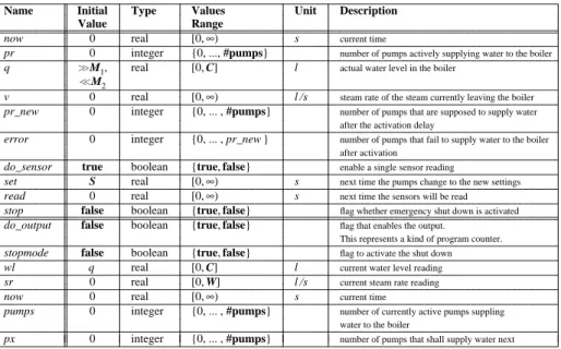
Several automata are specied in [12]: a boiler, a simple controller, the com-bination of these into a combined system, and a combined system with a fault-tolerant controller. Figure 2 presents, essentially verbatim, the specication of the simple combined system given in [12].2 In our study, we began by entering
the details of this specication into our timed automaton template.
Figure 3 shows a fragment of our template's version of this specication. This fragment includes the denitions of two (parameterized) predicates
steam rate pred
andwater level pred
(shown bold face for readability) that capture the constraints on the new steam ratev0 and water level q
0in the eect
of the time passage action (t), together with the (t) part of the
deni-tion of the template's transideni-tion funcdeni-tiontrans that encodes the eects of the actions dened in Figure 2. Appropriate applications of theoperator in a LET
construct allow the eect of the action (t) on state s to be expressed both
compactly and carefully.3 All the nondeterministic state components in either
the start state or in the transitions were similarly handled.
The major proof goal in [12] for the simple combined system was to establish two properties: either the steam rate has an acceptable value or the system is in the stop mode, and either the water level has an acceptable value or the system is in the stop mode. These two properties are expressed formally in [12] as:
Theorem 1:
In all reachable states of the boiler system,v <W
orstop =true
.Theorem 2:
In all reachable states of the boiler system,M
1< q <
M
2or stop =
true
.Although neither property mentions time explicitly, the correctness of the specication with respect to these properties is established by proving a sequence of state invariants that depend on time and thus relies heavily upon timing restrictions.
2 The meanings of several of the constants and variables are found in the above problem
description. The Appendix denes the remaining constants and variables.
3 The LET construct allows
to be used in encoding the denition of any state in which
two nondeterministic components are related (as is the case in the start state|where
qandwl, which satisfy the same predicate, must be equal|as well as in the result state of(t)) without the determinism of theoperator being taken for granted.
hhhhhhhhhhhhhhhhhhhhhhhhhhhhhhhhhhhhhhhhhhhhhhhhhhhhhhhhhhhhhhhhhhhhhhhhhhhhhhhhhhhhhh
State:
now, a nonnegative real, initially 0 do_sensor : boolean, initially true
do_output, stopmode, stop : boolean, initially false pr, pr_new, pumps, px : [0 .. #pumps], initially 0 error : [0 .. pr_new], initially 0
v, read : nonnegative real, initially 0 set : nonnegative real, initially S sr : [0,W], initially 0
q, wl : [0,C], initially equal and >> M1and << M2
Transitions:
actuator(e_stop,pset) sensor(s,w,p)
Precondition: Precondition:
do_output = true now = read
pset = px do_sensor = true
e_stop = stopmode stop = false
Effect: w = q
do_output′= false s = v
do_sensor′= true p = pr
pr_new′= pset Effect:
stop′= e_stop pumps′= p
read′= now + I do_sensor′= false do_output′= true
controller sr′= s
Precondition: wl′= w true
Effect: if sr′ ≤W−U1*I or
0≤px′ ≤#pumps wl′ ≥M2−P*(pumps′*S+(max_pumps_af ter_set ) *(I−S))+min_steam_water (sr ) or νν(∆t ) wl′ ≤M1−P*(pumps′*S+(min_pumps_af ter_set )
Precondition: *(I−S))+max_steam_water (sr )
stop = false then stopmode′= true
now+ ∆t≤read else stopmode′= {true, false} arbitrary now+ ∆t≤set
Effect: activate
v−U2*∆t≤v′ ≤v+U1*∆t Precondition:
q+pr *P*∆t− δHIGH(v , v′,∆t )≤q′ now=set q′ ≤q+pr *P*∆t− δLOW(v , v′,∆t ) stop=false now′ =now+ ∆t Effect:
set′ =read+S
0≤error′ ≤pr_new pr′ =pr_new−error
hhhhhhhhhhhhhhhhhhhhhhhhhhhhhhhhhhhhhhhhhhhhhhhhhhhhhhhhhhhhhhhhhhhhhhhhhhhhhhhhhhhhhh
Fig.2.Initial Specication of the Boiler System
4 Results
Extensions Required to Previous Methods.
Once the decision to model nondeterminism using the Hilbert was made, just two modications to thesystem used in our earlier study [2] were required before the system could be applied to hybrid systems. First, some necessary lemmas about real arithmetic were identied and included in a new auxiliary theory
real thy
. The other major modication involved : we developed a technique for using in specications(illustrated in Figure 3) and in proofs (illustrated in Figure 6).
Errors Discovered.
Using our proof system to analyze the Boiler, Controller, and combined Boiler System specications in [12] identied approximately ahhhhhhhhhhhhhhhhhhhhhhhhhhhhhhhhhhhhhhhhhhhhhhhhhhhhhhhhhhhhhhhhhhhhhhhhhhhhhhhhhhhhhh
steam_rate_pred(v_old:nonnegreal,delta_t:(fintime?))(v_new:nonnegreal):bool =
v_old−U_2*dur(delta_t) <= v_new & v_new <= v_old + U_1*dur(delta_t);
water_level_pred(q_old:water_level,pr:num_pumps,v_old,v_new:nonnegreal,delta_t:(fintime?))
(q_new:water_level):bool =
q_old + pr*P*dur(delta_t)−delta_HIGH(v_old,v_new,delta_t) <= q_new & q_new <= q_old + pr*P*dur(delta_t)−delta_LOW(v_old,v_new,delta_t); trans (a:actions, s:states):states =
CASES a OF
nu(delta_t): LET new_v_part = epsilon(steam_rate_pred(v(s),delta_t)),
new_q_part = epsilon(water_level_pred(q(s),pr(s),v(s),new_v_part,delta_t)) IN s WITH [now := now(s) + delta_t,
basic := basic(s) WITH [v_part := new_v_part, q_part := new_q_part]], <... other action cases ...>
ENDCASES;
hhhhhhhhhhhhhhhhhhhhhhhhhhhhhhhhhhhhhhhhhhhhhhhhhhhhhhhhhhhhhhhhhhhhhhhhhhhhhhhhhhhhhh
Fig.3.Specifying Nondeterminism Using
dozen errors.4These errors were discovered during each of the three basic stages
of the mechanization process: lling in the template, applying the PVS type checker, and checking the hand proofs of the invariants. The errors detected in lling in the template were usually due to vagueness in the original specication. For example, what is the meaning of the expressions \q <<
M
2" and \ q >>
M
1"? How is the water level variablew l in the Controller assigned the value
of the actual water level qin the Boiler when the Controller is considered as a
separate automaton?
In checking the hand proofs, several types of errors were found. The most common were missing assumptions about the constants. The second most com-mon were simple typographical errors. All of these errors, as well as the errors due to vagueness, are easily xed. To correct them, we determined what changes were needed to successfully complete the hand versions of the invariant proofs. While trivial, detecting and correcting these easily xable errors does clearly lead to better specications and better proofs.
Figure 4 shows an example of the type of feedback that occurs in the presence of an error. It shows the encoding of invariant lemma 3.3 of [12], and the goal of the sensor action proof branch generated by the induction strategy, with the precondition in hypothesis f{4g expanded. The goal is in the form of a
PVS Gentzen-stylesequent, where the conjunction of the hypotheses (numbered negatively) must be shown to imply the disjunction of the conclusions (numbered positively). Clearly, the proof on this branch would be valid if the inequality \sr 1
<= W { U 1 * I" in the condition in conclusion [2]|which is easily traceable to
the denition of the sensor action in Figure 2|were reversed. A little thought shows that the rst inequality in this denition is indeed backwards: one wants to prevent the steam ratesr
0 from becoming toolarge, not too small.
In addition to the minor errors described above, two more serious errors| errors in reasoning|were discovered. How to correct these errors was not obvi-ous. Like many of the minor errors, errors in reasoning were found when a dead
hhhhhhhhhhhhhhhhhhhhhhhhhhhhhhhhhhhhhhhhhhhhhhhhhhhhhhhhhhhhhhhhhhhhhhhhhhhhhhhhhhhhhhhhh
Inv_3_3(s: states):bool = (sr(s) + U_1*I < W) OR stopmode(s) = true; lemma_3_3: LEMMA (FORALL (s:states): reachable(s) => Inv_3_3(s));
hhhhhhhhhhhhhhhhhhhhhhhhhhhhhhhhhhhhhhhhhhhhhhhhhhhhhhhhhhhhhhhhhhhhhhhhhhhhhhhhhhhhhhhhh
lemma_3_3.2 : [−1] reachable(s_1)
[−2] (((sr_part(basic(s_1)) + U_1 * I) < W) OR stopmode_part(basic(s_1))) [−3] enabled_general(sensor(sr_1, w_1, p_1), s_1)
{−4} now(s_1) = fintime(read(s_1)) AND do_sensor(s_1) AND w_1 = q(s_1) AND sr_1 = v(s_1) AND p_1 = pr(s_1) AND NOT(stop(s_1))
|−−−−−−−
[1] (U_1 * I + sr_1 < W) [2] IF (sr_1 <= W−U_1 * I
OR ((w_1 >= ((((max(0, sr_part(basic(s_1))*I−U_2*I/2*I) + M_2)−(I*P*num_pumps))−P*S*p_1) + (P*S*num_pumps)))
OR (w_1 <= (M_1 + sr_part(basic(s_1))*I + U_1*I/2*I−P*S*p_1)))) THEN TRUE ELSE epsilon(bool_pred) ENDIF
hhhhhhhhhhhhhhhhhhhhhhhhhhhhhhhhhhhhhhhhhhhhhhhhhhhhhhhhhhhhhhhhhhhhhhhhhhhhhhhhhhhhhhhhh
Fig.4.Feedback Example.
end was reached on some branch of an induction proof. But, unlike the minor errors, making simple corrections to the specications or to the statements of the lemmas would not remedy the problems. In these cases, close examination of the corresponding parts of the original hand proofs revealed errors in reasoning. We note that the discovery of an error in the hand proof does not necessarily mean that a given assertion is false. It merely means that the assertion does not hold for the stated reasons. At least one invariant lemma in [12] (lemma 6) in fact had a simpler PVS proof than the hand proof supplied. When assertions hold for reasons other than the expected ones, one has to wonder whether the specication has in fact captured the required concepts.
Of the three modes of error discovery, the typechecking process produced the most varied results. Remedying the error in one case required extending the eect of an operator; in another, it required introducing a new invariant. A third \error" was one uncovered by the typechecker during a proof via the TCC (type-correctness condition) mechanism: when the{axiomwas invoked to assert
the corresponding predicate on the nondeterministic water-level componentq 0of
the result state of the time passage action, a TCC was generated that required proving thatq
0belongs to the correct subrange of values, namely [0,
C
]. \Error"is in quotes because this problem can be avoided by letting the water level range over all real values.5 Provided that it can be established, Theorem 2 will then
show that the water level does in fact stay within the physical limits.
Time Required to Check the Boiler Controller.
Checking the Boiler Con-troller solution required the checking of 14 lemmas and 2 theorems. The entire process of encoding three specications and checking the proofs (with backtrack-ing when corrections were made in the specication or statements of the lemmas) took less than 3 work weeks. Part of this time was spent designing and imple-menting modications to our system to support reasoning about nonlinear real arithmetic and nondeterminism. In a few proofs, we did not complete the check5However, the Boiler automaton as specied is then not a priori constrained in the
of the real arithmetic inequalities when this became too tedious in PVS and when their validity became obvious.
When all went smoothly, checking the proof of an invariant required on av-erage half an hour to an hour. Exceptions occurred in three induction proofs involving signicant reasoning about complex inequalities. For these, our basic induction strategy typically took between 10 and 15 minutes to reach the stage where the user could continue the proof by completing the base case and action cases, as opposed to times more on the order of 30 seconds for other induction proofs of invariants.6 The reason for this ineciency is a question for further
study.
5 A Proof Example
Most of the invariant proofs in our case study are very similar to the corre-sponding hand proofs. However, the PVS proofs required more detail when they involved either nondeterminism or suciently complicated nonlinear arithmetic. An example of a state invariant for the Boiler Controller specication in Fig-ure 2 that involves both reasoning about a nondeterministic action and nonlinear arithmetic is Lemma 11 in [12]. Figure 5 provides the statement and hand proof of Lemma 11 from [12]. Figure 6 shows the corresponding PVS proof using our specialized strategies.
This is one case in which no special help was required to allow PVS to reason about the real arithmetic: this aspect of the proof can be done by applying equalities, expanding products, and matching the resulting terms, all of which the primitive proof steps of PVS can do automatically.
On the other hand, PVS does need help at the point where the constraints on the nondeterministic valuev
0, the steam rate in the result state, are introduced.
The step in the PVS proof which does this is the
USE EPSILON
step. Theeect of this step is to invoke the{axiomfor the (parameterized) predicateP =
steam rate pred(v(s 1), t 1)
and the type =nonneg r eal, thus creating thetwo proof branches represented by the cases \1" and \2" that follow this step. In the rst branch, the required constraints on v
0=
(P) have been introduced
into the hypotheses of the current goal. In the second branch, it is required to prove that there does indeed exist a possible value forv
0|that is, that there is
indeed a value of type nonnegreal satisfying P. This is done by supplying the
instancev(s 1). This branch is necessary because of the form of the{axiom(see
Section 3.1).
6 Conclusions
Applying our proof system to a solution of the Steam Boiler Controller prob-lem led to several insights about the utility of our approach to specifying and verifying hybrid systems. We discuss these insights below.
Mechanizing Specications and Proofs.
The results of our study clearly demonstrate the utility of mechanized tools for detecting and correcting errors in both formal specications and formal proofs. While verication systems that use totally automatic proof methods can provide some limited feedback, the generality of interactive theorem proving provides more specic, and therefore more useful, feedback. The feedback we obtained from the PVS typechecker andhhhhhhhhhhhhhhhhhhhhhhhhhhhhhhhhhhhhhhhhhhhhhhhhhhhhhhhhhhhhhhhhhhhhhhhhhhhhhhhhhh Lemma 11: In all reachable states of the combined steam boiler system,
v+U1*(read−now ) < W or stop=true
Proof. The basis is vacuously satisfied. We distinguish on the cases for the action a . For
a∈{sensor, activate} this lemma is trivially true. Otherwise we get: A) a = actuator (v , stop , and now are unchanged):
We know sr+U1*I < W or stopmode =true (Lemma 3.3), do_output =true from the
precondition and if do_output then now =read and sr =v (Lemma 4). From this we
can infer v+U1*(now+I−now ) < W or stopmode =true. Moreover, we get
stop′ =e_stop=stopmode and read′ =now+I from the effect and thus, we know
v+U1*(read′ −now ) < W or stop =true.
B) a = time-passage (read and stop are unchanged):
We know from the precondition stop =false and v+U1*(read−now ) < W from the
assumption. This is equivalent to v+U1*(read−now− ∆t+ ∆t ) < W and it follows
v+U1*∆t+U1*(read−now− ∆t ) < W. Since we know from the effect v′ ≤v+U1*∆t and now′ =now+ ∆t , finally, this is equivalent to v′ +U1*(read−now′) < W. `
hhhhhhhhhhhhhhhhhhhhhhhhhhhhhhhhhhhhhhhhhhhhhhhhhhhhhhhhhhhhhhhhhhhhhhhhhhhhhhhhhh
Fig.5.Hand Proof of Lemma 11
hhhhhhhhhhhhhhhhhhhhhhhhhhhhhhhhhhhhhhhhhhhhhhhhhhhhhhhhhhhhhhhhhhhhhhhhhhhhhhhhhhhhhhhhhhhh
Inv_11(s: states): bool = (v(s) + U_1*(read(s)−dur(now(s))) < W OR stop(s) = true); lemma_11: LEMMA ( FORALL (s: states): reachable(s) => Inv_11(s) );
("" (AUTO_PROOF_BOILERSYS "Inv_11")
(("1" (APPLY (THEN (EXPAND "enabled_specific") (BOILERSYS_SIMP)) "Case nu(t_1)." "Invoke the precondition.")
(APPLY (THEN (USE_EPSILON "nonnegreal" "steam_rate_pred" "v(s_1)" "t_1") (BOILERSYS_SIMP)) "Invoke the restrictions on v′.")
(("1" (TIME_ETC_SIMP))
("2" (APPLY (THEN (EXPAND "steam_rate_pred" 1) (BOILERSYS_SIMP)) "Doing the existence proof for epsilon.")
(APPLY (THEN (INST 1 "v(s_1)") (BOILERSYS_SIMP))) (TIME_ETC_SIMP))))
("2" (APPLY (THEN (APPLY_INV_LEMMA "3_3") (BOILERSYS_SIMP)) "Case actuator(e_1,p_1).")
(APPLY (THEN (EXPAND "enabled_specific") (BOILERSYS_SIMP)) "Invoke the precondition.")
(APPLY (THEN (APPLY_INV_LEMMA "4") (BOILERSYS_SIMP))))))
hhhhhhhhhhhhhhhhhhhhhhhhhhhhhhhhhhhhhhhhhhhhhhhhhhhhhhhhhhhhhhhhhhhhhhhhhhhhhhhhhhhhhhhhhhhh
Fig.6.PVS Proof of Lemma 11
from reaching dead ends in proofs not only localized the source of an error but often made it easy for us to to correct the error. Moreover, the time required to check the specications and the proofs was not signicant.
Using Specialized Tools.
We have applied the system that we developed for our initial study [2] to two additional problems, the Boiler Controller bench-mark and the proof of a timed version of Fischer's algorithm [13]. In each of the later applications, our earlier-developed system greatly simplied the specica-tion and proof process. Each new applicaspecica-tion of the system led to some addispecica-tions: the automata in Fischer's algorithm were a special class of timed automata that represent MMT automata [17]; those in the current study involved nondetermin-ism and nonlinear real arithmetic. However, the needed enhancements required the addition of only a very small number of new proof strategies, sometimes withspecication conventions to support them. The total time required for solving each of the two later problems, which included the time needed to add the re-quired enhancements, was less than three work weeks.
It is not clear when we will reach the point where applying our proof system requires no additions. Our experience so far is that one can build upon the previously developed system. Further, while we have not yet reached the point where our system can be applied by users who lack knowledge of PVS, we believe that use of our system reduces the time and eort that are required to check proofs, while providing meaningful feedback about errors.
On Reasoning About Nondeterministic Automata.
For ecient reasoningabout nondeterministic automata in PVS, our current solution is to represent the transition relation as a function by making (careful) use of the Hilbert. We
be-lieve that incorporation of \ANY" and \SOME" constructs with accompanying skolemization and instantiation would be useful additions to PVS for reasoning about nondeterminism, since this would help solve the problem of the results of actions being represented in PVS as deterministic (though nonspecic).
The desire to represent the transition relation as a function also partly arises from the intuition that the intention in specications such as the one in this study is that transitions should be enabled when their preconditions are sat-ised: that is, that they can then \re". Thus, the transition relation should be considered to be a many-valued (but never no-valued) function. Note, this interpretation involves an implicit proof obligation for any such specication: one must demonstrate the existence of at least one result state satisfying the constraints of every legal transition. We note that PVS naturally enforces this requirement, since it demands that all functions be total.
On Using PVS.
While there are no complete decision procedures for reason-ing about inequalities involvreason-ing nonlinear real arithmetic, our experience so far indicates that the human guidance PVS is likely to need in reasoning about hybrid automata is the application of a small number of facts about the real numbers, together with control over the grouping of terms into factors. It should be possible to design specialized PVS strategies that will provide much of the needed guidance. These strategies fall into two categories: those that simplify ap-plication of lemmas about real arithmetic, and what could be called \naming" strategies, strategies that simplify the use of names for terms. The second type can also be helpful in simplifying the job of the human user of PVS, since they could also be used to manage expressions, such asepsilon
expressions, that do not necessarily involve a sum of terms, but are simply long. The implementation of at least some of these strategies will require the use of certain enhancements to PVS that are in progress, such as the ability to name and track assertions. Whether strategies can be designed that execute with acceptable speed remains an open question.Acknowledgments
We wish to thank Gunter Leeb and Nancy Lynch for sharing a challenging exam-ple with us; Steve Garland, Gunter Leeb, Victor Luchangco, and Nancy Lynch for insightful discussions; and the anonymous reviewers for helpful comments.
References
1. J.-R. Abrial, E. Boerger, and H. Langmaack. Preliminary report for the Dagstuhl-Seminar 9523: Methods for Semantics and Specication. Dagstuhl, June 1995. 2. M. Archer and C. Heitmeyer. Mechanical verication of timed automata: A
case study. In Proc. 1996 IEEE Real-Time Technology and Applications Symp. (RTAS'96). IEEE Computer Society Press, 1996.
3. M. Archer and C. Heitmeyer. Verifying hybrid systems modeled as timed au-tomata: A case study. Technical report, NRL, Wash., DC, 1997. In preparation. 4. R. Boyer and J. Moore.A Computational Logic. Academic Press, 1979.
5. S. Campos, E. Clarke, and M. Minea. Analysis of real-time systems using symbolic techniques. InFormal Methods for Real-Time Computing, chapter 9. John Wiley & Sons, 1996.
6. M. J. C. Gordon and T. Melham, editors. Introduction to HOL: A Theorem Prov-ing Environment for Higher-Order Logic. Cambridge University Press, 1993. 7. C. Heitmeyer and N. Lynch. The Generalized Railroad Crossing: A case study in
formal verication of real-time systems. InProc., Real-Time Systems Symp., San Juan, Puerto Rico, Dec. 1994.
8. C. Heitmeyer and N. Lynch. The Generalized Railroad Crossing: A case study in formal verication of real-time systems. Technical Report MIT/LCS/TM-51, Lab. for Comp. Sci., MIT, Cambridge, MA, 1994. Also TR 7619, NRL, Wash., DC 1994. 9. C. Heitmeyer and D. Mandrioli, editors. Formal Methods for Real-Time
Comput-ing. Number 5 in Trends in Software. John Wiley & Sons, 1996.
10. T. Henzinger and P. Ho. Hytech: The Cornell Hybrid Technology Tool. Technical report, Cornell University, 1995.
11. R. P. Kurshan. Computer-Aided Verication of Coordinating Processes: the
Automata-Theoretic Approach. Princeton University Press, 1994.
12. G. Leeb and N. Lynch. Proving safety properties of the Steam Boiler Controller: Formal methods for industrial applications: A case study. In J.-R. Abrial, et al., eds.,Formal Methods for Industrial Applications: Specifying and Programming the Steam Boiler Control, vol. 1165 ofLect. Notes in Comp. Sci.Springer-Verlag, 1996. 13. V. Luchangco. Using simulation techniques to prove timing properties. Master's
thesis, Massachusetts Institute of Technology, June 1995.
14. N. Lynch and F. Vaandrager. Forward and backward simulations { Part II: Timing-based systems. To appear inInformation and Computation.
15. N. Lynch and F. Vaandrager. Forward and backward simulations for timing-based systems. InProc. of REX Workshop \Real-Time: Theory in Practice", volume 600 ofLecture Notes in Computer Science, pages 397{446. Springer-Verlag, 1991. 16. K. L. McMillan. Symbolic Model Checking. Kluwer Academic Publishers, 1993. 17. M. Merritt, F. Modugno, and M. R. Tuttle. Time constrained automata. In J.
C. M. Baeten and J. F. Goote, eds., CONCUR'91: 2nd Intern. Conference on Concurrency Theory, vol. 527 ofLect. Notes in Comp. Sci.Springer-Verlag, 1991. 18. S. Owre, J. Rushby, N. Shankar, and F. von Henke. Formal verication for fault-tolerant architectures: Prolegomena to the design of PVS. IEEE Transactions on Software Engineering, 21(2):107{125, Feb. 1995.
19. N. Shankar, S. Owre, and J. Rushby. The PVS proof checker: A reference manual. Technical report, Computer Science Lab., SRI Intl., Menlo Park, CA, 1993. 20. J. Vitt and J. Hooman. Assertional Specication and Verication Using PVS of
the Steam Boiler Control System. In J.-R. Abrial et al., editors,Formal Methods for Industrial Applications: Specifying and Programming the Steam Boiler Control, volume 1165 ofLect. Notes in Comp. Sci.Springer-Verlag, 1996.
A Appendix. Constant and Variable Denitions
iiiiiiiiiiiiiiiiiiiiiiiiiiiiiiiiiiiiiiiiiiiiiiiiiiiiiiiiiiiiiiiiiiiiiiiiiiiiiiiiiiName Type Unit Description
iiiiiiiiiiiiiiiiiiiiiiiiiiiiiiiiiiiiiiiiiiiiiiiiiiiiiiiiiiiiiiiiiiiiiiiiiiiiiiiiii iiiiiiiiiiiiiiiiiiiiiiiiiiiiiiiiiiiiiiiiiiiiiiiiiiiiiiiiiiiiiiiiiiiiiiiiiiiiiiiiii
I real, >0 s time between the periodical sensor reading
iiiiiiiiiiiiiiiiiiiiiiiiiiiiiiiiiiiiiiiiiiiiiiiiiiiiiiiiiiiiiiiiiiiiiiiiiiiiiiiiii
S real, >0 s delay to activate pumps after the last sensor reading
iiiiiiiiiiiiiiiiiiiiiiiiiiiiiiiiiiiiiiiiiiiiiiiiiiiiiiiiiiiiiiiiiiiiiiiiiiiiiiiiii
U1 real, >0 l /s2 maximum gradient of the increase of the steam rate
iiiiiiiiiiiiiiiiiiiiiiiiiiiiiiiiiiiiiiiiiiiiiiiiiiiiiiiiiiiiiiiiiiiiiiiiiiiiiiiiii
U2 real, >0 l /s2 maximum gradient of the decrease of the steam rate
iiiiiiiiiiiiiiiiiiiiiiiiiiiiiiiiiiiiiiiiiiiiiiiiiiiiiiiiiiiiiiiiiiiiiiiiiiiiiiiiii
M1 real, >0 l minimum amount of water before boiler becomes critical
iiiiiiiiiiiiiiiiiiiiiiiiiiiiiiiiiiiiiiiiiiiiiiiiiiiiiiiiiiiiiiiiiiiiiiiiiiiiiiiiii
M2 real, >0 l maximum amount of water before boiler becomes critical
iiiiiiiiiiiiiiiiiiiiiiiiiiiiiiiiiiiiiiiiiiiiiiiiiiiiiiiiiiiiiiiiiiiiiiiiiiiiiiiiii
W real, >0 l /s maximum steam rate before boiler becomes critical
iiiiiiiiiiiiiiiiiiiiiiiiiiiiiiiiiiiiiiiiiiiiiiiiiiiiiiiiiiiiiiiiiiiiiiiiiiiiiiiiii
P real, >0 l /s exact rate at which one active pump supplies water to the boiler
iiiiiiiiiiiiiiiiiiiiiiiiiiiiiiiiiiiiiiiiiiiiiiiiiiiiiiiiiiiiiiiiiiiiiiiiiiiiiiiiii
#pumps int, >0 Number of pumps that can supply water to the boiler in parallel
iiiiiiiiiiiiiiiiiiiiiiiiiiiiiiiiiiiiiiiiiiiiiiiiiiiiiiiiiiiiiiiiiiiiiiiiiiiiiiiiii
C real, >0 l Capacity of the boiler
iiiiiiiiiiiiiiiiiiiiiiiiiiiiiiiiiiiiiiiiiiiiiiiiiiiiiiiiiiiiiiiiiiiiiiiiiiiiiiiiii cc c c c c c c c c c c c c c cc c c c c c c c c c c c c c cc c c c c c c c c c c c c c cc c c c c c c c c c c c c c cc c c c c c c c c c c c c c cc c c c c c c c c c c c c c
Table1.Constants for the Boiler and Controller Models
iiiiiiiiiiiiiiiiiiiiiiiiiiiiiiiiiiiiiiiiiiiiiiiiiiiiiiiiiiiiiiiiiiiiiiiiiiiiiiiiiiiiiiiiiiiiiiii
Name Initial Type Values Unit Description Value Range
iiiiiiiiiiiiiiiiiiiiiiiiiiiiiiiiiiiiiiiiiiiiiiiiiiiiiiiiiiiiiiiiiiiiiiiiiiiiiiiiiiiiiiiiiiiiiiii iiiiiiiiiiiiiiiiiiiiiiiiiiiiiiiiiiiiiiiiiiiiiiiiiiiiiiiiiiiiiiiiiiiiiiiiiiiiiiiiiiiiiiiiiiiiiiii
now 0 real [0,∞) s current time
iiiiiiiiiiiiiiiiiiiiiiiiiiiiiiiiiiiiiiiiiiiiiiiiiiiiiiiiiiiiiiiiiiiiiiiiiiiiiiiiiiiiiiiiiiiiiiii
pr 0 integer {0, ..., #pumps} number of pumps actively supplying water to the boiler
iiiiiiiiiiiiiiiiiiiiiiiiiiiiiiiiiiiiiiiiiiiiiiiiiiiiiiiiiiiiiiiiiiiiiiiiiiiiiiiiiiiiiiiiiiiiiiii
q >>M1, real [0, C] l actual water level in the boiler
<<M2
iiiiiiiiiiiiiiiiiiiiiiiiiiiiiiiiiiiiiiiiiiiiiiiiiiiiiiiiiiiiiiiiiiiiiiiiiiiiiiiiiiiiiiiiiiiiiiii
v 0 real [0,∞) l /s steam rate of the steam currently leaving the boiler
iiiiiiiiiiiiiiiiiiiiiiiiiiiiiiiiiiiiiiiiiiiiiiiiiiiiiiiiiiiiiiiiiiiiiiiiiiiiiiiiiiiiiiiiiiiiiiii
pr_new 0 integer {0, ... , #pumps} number of pumps that are supposed to supply water
after the activation delay
iiiiiiiiiiiiiiiiiiiiiiiiiiiiiiiiiiiiiiiiiiiiiiiiiiiiiiiiiiiiiiiiiiiiiiiiiiiiiiiiiiiiiiiiiiiiiiii
error 0 integer {0, ... , pr_new } number of pumps that fail to supply water to the boiler after activation
iiiiiiiiiiiiiiiiiiiiiiiiiiiiiiiiiiiiiiiiiiiiiiiiiiiiiiiiiiiiiiiiiiiiiiiiiiiiiiiiiiiiiiiiiiiiiiii
do_sensor true boolean {true, false} enable a single sensor reading
iiiiiiiiiiiiiiiiiiiiiiiiiiiiiiiiiiiiiiiiiiiiiiiiiiiiiiiiiiiiiiiiiiiiiiiiiiiiiiiiiiiiiiiiiiiiiiii
set S real [0,∞) s next time the pumps change to the new settings
iiiiiiiiiiiiiiiiiiiiiiiiiiiiiiiiiiiiiiiiiiiiiiiiiiiiiiiiiiiiiiiiiiiiiiiiiiiiiiiiiiiiiiiiiiiiiiii
read 0 real [0,∞) s next time the sensors will be read
iiiiiiiiiiiiiiiiiiiiiiiiiiiiiiiiiiiiiiiiiiiiiiiiiiiiiiiiiiiiiiiiiiiiiiiiiiiiiiiiiiiiiiiiiiiiiiii
stop false boolean {true, false} flag whether emergency shut down is activated
iiiiiiiiiiiiiiiiiiiiiiiiiiiiiiiiiiiiiiiiiiiiiiiiiiiiiiiiiiiiiiiiiiiiiiiiiiiiiiiiiiiiiiiiiiiiiiii iiiiiiiiiiiiiiiiiiiiiiiiiiiiiiiiiiiiiiiiiiiiiiiiiiiiiiiiiiiiiiiiiiiiiiiiiiiiiiiiiiiiiiiiiiiiiiii
do_output false boolean {true, false} flag that enables the output.
This represents a kind of program counter.
iiiiiiiiiiiiiiiiiiiiiiiiiiiiiiiiiiiiiiiiiiiiiiiiiiiiiiiiiiiiiiiiiiiiiiiiiiiiiiiiiiiiiiiiiiiiiiii
stopmode false boolean {true, false} flag to activate the shut down
iiiiiiiiiiiiiiiiiiiiiiiiiiiiiiiiiiiiiiiiiiiiiiiiiiiiiiiiiiiiiiiiiiiiiiiiiiiiiiiiiiiiiiiiiiiiiiii
wl q real [0, C] l current water level reading
iiiiiiiiiiiiiiiiiiiiiiiiiiiiiiiiiiiiiiiiiiiiiiiiiiiiiiiiiiiiiiiiiiiiiiiiiiiiiiiiiiiiiiiiiiiiiiii
sr 0 real [0, W] l /s current steam rate reading
iiiiiiiiiiiiiiiiiiiiiiiiiiiiiiiiiiiiiiiiiiiiiiiiiiiiiiiiiiiiiiiiiiiiiiiiiiiiiiiiiiiiiiiiiiiiiiii
now 0 real [0,∞) s current time
iiiiiiiiiiiiiiiiiiiiiiiiiiiiiiiiiiiiiiiiiiiiiiiiiiiiiiiiiiiiiiiiiiiiiiiiiiiiiiiiiiiiiiiiiiiiiiii
pumps 0 integer {0, ... , #pumps} number of currently active pumps suppling
water to the boiler
iiiiiiiiiiiiiiiiiiiiiiiiiiiiiiiiiiiiiiiiiiiiiiiiiiiiiiiiiiiiiiiiiiiiiiiiiiiiiiiiiiiiiiiiiiiiiiii
px 0 integer {0, ... , #pumps} number of pumps that shall supply water next
iiiiiiiiiiiiiiiiiiiiiiiiiiiiiiiiiiiiiiiiiiiiiiiiiiiiiiiiiiiiiiiiiiiiiiiiiiiiiiiiiiiiiiiiiiiiiiii cc c c c c c c c c c c c c c c c c c c c c c c c c c c c c cc c c c c c c c c c c c c c c c c c c c c c c c c c c c c cc c c c c c c c c c c c c c c c c c c c c c c c c c c c c cc c c c c c c c c c c c c c c c c c c c c c c c c c c c c cc c c c c c c c c c c c c c c c c c c c c c c c c c c c c cc c c c c c c c c c c c c c c c c c c c c c c c c c c c c cc c c c c c c c c c c c c c c c c c c c c c c c c c c c c cc c c c c c c c c c c c c c c c c c c c c c c c c c c c c
Table 2.Variables for the Boiler and Controller Models
iiiiiiiiiiiiiiiiiiiiiiiiiiiiiiiiiiiiiiiiiiiiiiiiiiiiiiiiiiiiiiiiiiiiiiiiiiiiiiiiiiiiiiiiiiiiiiiiiiiiiiiiiiiiiii
Name Type Unit Value Description
iiiiiiiiiiiiiiiiiiiiiiiiiiiiiiiiiiiiiiiiiiiiiiiiiiiiiiiiiiiiiiiiiiiiiiiiiiiiiiiiiiiiiiiiiiiiiiiiiiiiiiiiiiiiiii iiiiiiiiiiiiiiiiiiiiiiiiiiiiiiiiiiiiiiiiiiiiiiiiiiiiiiiiiiiiiiiiiiiiiiiiiiiiiiiiiiiiiiiiiiiiiiiiiiiiiiiiiiiiiii
max_pumps_af ter_set integer #pumps maximum number of pumps that can supply water to the boiler after the delay considering the pump failure model.
iiiiiiiiiiiiiiiiiiiiiiiiiiiiiiiiiiiiiiiiiiiiiiiiiiiiiiiiiiiiiiiiiiiiiiiiiiiiiiiiiiiiiiiiiiiiiiiiiiiiiiiiiiiiiii
min_pumps_af ter_set integer 0 minimum number of pumps that can supply water to the boiler after the delay considering the pump failure model.
iiiiiiiiiiiiiiiiiiiiiiiiiiiiiiiiiiiiiiiiiiiiiiiiiiiiiiiiiiiiiiiiiiiiiiiiiiiiiiiiiiiiiiiiiiiiiiiiiiiiiiiiiiiiiii
max_steam_water (sr ) real l max(0, (sr−U2*I/2)*I ) minimum amount of water that can evaporate into steam
until the next sensor reading
iiiiiiiiiiiiiiiiiiiiiiiiiiiiiiiiiiiiiiiiiiiiiiiiiiiiiiiiiiiiiiiiiiiiiiiiiiiiiiiiiiiiiiiiiiiiiiiiiiiiiiiiiiiiiii
min_steam_water (sr ) real l (sr+U1*I/2)*I maximum amount of water that can evaporate into steam until the next sensor reading
iiiiiiiiiiiiiiiiiiiiiiiiiiiiiiiiiiiiiiiiiiiiiiiiiiiiiiiiiiiiiiiiiiiiiiiiiiiiiiiiiiiiiiiiiiiiiiiiiiiiiiiiiiiiiii c c c c c c c c c c c c c c c c c c c c c c c c c c c c c c c c c c c c c c c c c c c c c c c c c c c c c c c c c c c c c c c c c c c c c c c c c c c c c
Table 3.Additional Denitions for the Controller Model