IOS Press
Fast cone-beam CT image reconstruction
using GPU hardware
Guorui Yan, Jie Tian∗, Shouping Zhu, Yakang Dai and Chenghu Qin
Medical Image Processing Group, Key Laboratory of Complex Systems and Intelligence Science, Institute of Automation, Chinese Academy of Sciences, Graduate School of the Chinese Academy of Sciences, P. O. Box 2728, Beijing, 100190, China
Received 31 December 2007 Revised 20 May 2008 Accepted 29 July 2008
Abstract. Three dimension Computed Tomography (CT) reconstruction is computationally demanding. To accelerate the speed of reconstruction, Application Specific Integrated Circuit (ASIC) or Field Programmable Gate Array (FPGA) has been used, but they are expensive, inflexible and not easy to upgrade. The modern Graphics Processing Unit (GPU) with its programmable features improves this situation and becomes one of the powerful and flexible tools for 3D CT reconstruction. In this paper, we implement Feldkamp-Davis-Kress (FDK) algorithm on commodity GPU using an acceleration scheme. In the scheme, two techniques are developed and combined. One is cyclic render-to-texture (CRTT) which saves the copy time, and the other is the combination of z-axis symmetry and multiple render targets (MRTs), which reduces the computational cost on the geometry mapping between slices to be reconstructed and projection views. Our algorithm performs reconstruction of a 5123 volume from 360 views of the size 512×512 about 5.2s on a single NVIDIA GeForce 8800GTX card.
Keywords: Computed tomography, GPU, CRTT, symmetry, cone-beam reconstruction, FDK
1. Introduction
Computed tomography (CT) has become one of the most prevalent tools in medical diagnosis and industrial non-destructive testing. However, 3D CT image reconstruction is computationally demanding at computational complexity ofO(N M3), whereN andM are respectively the number of projection views and volumetric pixels in one dimension. Due to high computational complexity, reconstruction time has become one of the most important features of appraising a CT scanner. To accelerate the speed of reconstruction, ASIC or FPGA has been used, but they are expensive, inflexible and not easy to upgrade. With the emergence of programmable Graphics Processing Unit (GPU), some high-performance and more flexible CT image reconstruction algorithms have been implemented on GPU.
Nowadays, the two major GPU manufacturers are NVIDIA and ATI (acquired by AMD). We briefly introduce the NVIDIA GPU hardware [7] and the introduction of the counterpart made by ATI can been found in [5] . The firstly named “GeForce” GPU hardware is the GeForce 256 released in 1999. Now the GeForce 8 series have been released. In these NVIDIA GPUs, programmable vertex shaders and pixel
∗Corresponding author. Tel.: +86 10 8261 8465; Fax: +86 10 6252 7995; E-mails: [email protected], [email protected]. 0895-3996/08/$17.002008 – IOS Press and the authors. All rights reserved
(a) (b)
Thread Processor
Fig. 1. Comparison of classic GPU pipeline and the latest GPU pipeline in block diagrams: (a) Classic GPU pipeline; (b) Latest GeForce 8800GTX GPU pipeline.
shaders were introduced by GeForce 3 series in 2001, allowing developers to exploit specialized program to manipulate vertex and pixel data. Floating-point precision was supported by GeForce FX series, and FP16 (partial precision, 16bit floating point) texture filtering and frame buffer blending in hardware were introduced from GeForce 6 series, which means that we can only do nearest-interpolation operations directly when using 32-bit floating-point data. Certainly we can implement bilinear-interpolation through shader programs. Until GeForce 8 series, 32-bit per component floating-point texture filtering and blending in hardware are supported. The main difference between GeForce 8 series and the previous is the introduction of unified shader architecture. Classic GPU pipelines implement vertex shaders and fragment shaders separately, while the GeForce 8 series GPU pipelines with unified shader architecture do not discriminate the vertex shaders and fragment shaders, which makes full use of shaders avoiding too vertex-shader intensive or too fragment-shader intensive [10]. Rendering process generally begins with vertices with various attributes passed into GPU from CPU, then vertex shading, rasterization, fragment shading and finally write pixels to framebuffer. The comparison of rendering process between classic GPU and GeForce 8800GTX is illustrated in Fig. 1.
With its rapid development, GPU owns more powerful raw computational performance than CPU does. Zeng [19] recently proposed an optimization scheme based on CPU, which needs 387.9ms reconstructing a 512×512 cross from 360 projection views, while Xu’s reconstruction algorithm [16] based on GPU just needs 17.4ms. With powerful computing performance and programmable characteristic, GPUs have emerged as an attractive platform for accelerating both graphics and other algorithms [4,11]. From early fixed-function pipelines to currently fully programmable, from outputting 8-bit-per-channel color values to full IEEE single precision, GPUs become more and more powerful and flexible. Accompany with the generation of GPUs, accelerated CT reconstruction algorithms based on contemporaneous GPUs generate. From Cabral [1] first implemented the accelerated CT reconstruction on nonprogrammable SGI workstation to Xu [16] developed AG-GPU mechanism on the latest commercial GeForce 8800GTX GPU then to Yang [17] performed the backprojection using CUDA architecture, all of these prove that GPU is very suitable for CT image reconstruction.
In this paper, a 3D texture, instead of stacks of 2D textures that previously did, is used for storing the reconstructed volume. So the OpenGL “GL EXT framebuffer object” extension should be supported by hardware. The latest GeForce 8800 series GPU fully supports that. We implement FDK algorithm using 3D texture, and develop two novel accelerating techniques. One is cyclic render-to-texture (CRTT)
e y e x e z θ v x v y v z R L d w d h a b
Fig. 2. Analogy between backprojection and projective texture mapping. Analogize the volume coordinate space(xv, yv, zv) to the object space in computer graphics, and analogize the source-detector space(xe, ye, ze)to the eye space in computer graphics;R: source-center distance;L: source-detector distance;wd,hd: detector width and height.
which saves the copy time, and the other is the combination of z-axis symmetry and multiple render targets (MRTs), which reduces the computational cost on the geometry mapping between slices to be reconstructed and projection views. The techniques can also be used in other case, such as the misaligned-geometry cone-beam CT reconstruction [15].
The rest of this paper is organized as follows. Section 2 describes FDK algorithm in two steps briefly. Section 3 describes the backprojection geometry in traditional computer graphics model, then accelerating algorithms of CRTT, symmetry, MRTs, and some other skills are presented. In Section 4 experiments and results are presented and conclusions of this paper are made in Section 5.
2. FDK algorithm from planar detector data
Though non-planar acquisition orbits [21] and some exact reconstruction algorithms [20] have been developed, the cone-beam scanning configuration with a circular orbit remains one of the most popular configurations and has been widely employed for data acquisition [18], and the most widely used reconstruction algorithm remains to be FDK [2] reconstruction algorithm in this circumstance. Let pC(θ, a, b) denote cone-beam projection data from planar detector, where θ is projection angle and (a, b) is the coordinate of a virtual detector plane at the rotation center as illustrated in Fig. 2, and let f(xv, yv, zv) represent the spatial function to be reconstructed. The FDK algorithm has two stages:
weighted-filter in projection-space and weighted-backprojection in volume-space [13]. First step, weighted-filter:
˜ pC(θ, a, b) = R2 √ R2+a2+b2p C(θ, a, b) ∗gP (a) (1)
Where,Ris the source-center distance, √ R2
R2+a2+b2is the production of two cosine factors of the
fan-and cone-angle, fan-andgP(a)is a ramp-filter. Second step, weighted-backprojection:
f(xv, yv, zv) = θ
R2 U(xv, yv, θ)
Where U(xv, yv, θ) =R+xvcosθ+yvsinθ (3) a(xv, yv, θ) =R xvsinθ−yvcosθ R+xvcosθ+yvsinθ (4) b(xv, yv, zv, θ) =zv R R+xvcosθ+yvsinθ (5)
In most cases, a(xv, yv, θ) and b(xv, yv, zv, θ) are not just integers, so the interpolation is to be implemented.
3. Backprojection geometry and accelerated algorithms
The mapping between planar detector and a slice to be reconstructed is a projection transform [13], which is commonly known as projective texture mapping [12] in computer graphics. Cabral [1] first implemented the accelerated CT reconstruction using projective texture mapping, and the most of following GPU accelerated algorithms were based on texture mapping because of the similarity between backprojection and projective texture mapping. Xu [16] used the latest programmable GeForce 8800GTX GPU and generated a good result. Based on these existing researches, we furthered two novel techniques to improve the reconstruction speed.
3.1. Analogy between backprojection and projective texture mapping
As mentioned above, cone-beam backprojection is very similar to projective texture mapping. As illustrated in Fig. 2, the volume space(xv, yv, zv)and the source-detector space(xe, ye, ze)are analogized
to the object space and eye space in computer graphics respectively. Just as computer graphics does, projection transform can be divided into a model matrixM, a view matrixV,a perspective matrixPand a translation and scaling matrixT S. Since texture index is usually in [0, 1], the matrixT Sis necessary. The matrixMcorresponds to the rotation of a cone-beam CT. The matrixV reveals the distance between x-ray source and rotation center and transforms the volume space to the source-detector space. The matrixPis a perspective transform. We can obtain the mapping between the volume to be reconstructed and projection data in homogeneous as in computer graphics does:
xe ye ze we =T S×P×V ×M xv yv zv 1 = 0.5 0 0 0.5 0 0.5 0 0.5 0 0 1 0 0 0 0 1 2L wd 0 0 0 0 2L hd 0 0 0 0 C D 0 0 −1 0 0 −1 0 0 0 0 1 0 −1 0 0−R 0 0 0 1 cosθ sinθ0 0 −sinθcosθ0 0 0 0 1 0 0 0 0 1 xv yv zv 1 (6)
Where,wdandhdare detector width and height respectively. Ris the source-center distance andLis
end end t s a projectDat w V V V slice each for a projectDat texture a to view filtered the load CPU on view projection the filter angle each for tex tex m m m ) , ( * ) ( + = θ
Fig. 3. Schematic diagram showing CT reconstruction algorithm using GPU.Vm: a slice to be reconstructed;stex,
ttex: the mapping coordinates in detector space ofVm;w: the weight;projectData: a texture for storing projection data.
our work. Dividing all components byweto obtain the mapping coordinate(stex, ttex)in texture space
(normalized detector plane) of the voxel(xv, yv, zv):
stex(xv, yv, θ) = xe we = xv cosθ 2 +Lwsindθ +yv sinθ 2 −Lwcosdθ +R 2 R+xvcosθ+yvsinθ (7) ttex(xv, yv, zv, θ) = ye we = xvcos2θ +yvsin2θ +zvhLd +R2 R+xvcosθ+yvsinθ (8)
The relationship between the Eqs (7), (8) and (4), (5) is thatstex(xv, yv, θ)andttex(xv, yv, zv, θ)are the normalization ofa(xv, yv, θ)andb(xv, yv, zv, θ)respectively. In the implementation,T S×P×V is calculated once and stored in a matrix, multiplied by the rotation matixMat each projection.
3.2. Cyclic render-to-texture
Data are often stored in textures in GPU memory when GPU programming. In the early reconstruction algorithms, volume data were stored in stacks of 2D textures maybe because 3D texture was not efficiently supported then. By numerical and careful experiments, we find 3D texture can work well, so here the volume data are stored in a 3D texture. Weighted-filtering is performed on CPU using FFTW [3], and the backprojection and accumulation are performed on GPU. The reconstruction process can be schematically illustrated as Fig. 3: For each projection angle, load the filtered projection view to a texture and update each slice by this projection view. Deal with the next projection view until all the angle projection views are processed.
Unfortunately, due to the architecture of GPU, the same memory locations cannot be read and written concurrently. For example, if you want to get a 2D array sum ofA+B, a new 2D texture must be allocated for saving the result. NeitherAnorBcan be reused for saving the results, because the memory block bound to framebuffer is write-only. However, as shown in Fig. 3, 2D array addition is very common in CT reconstruction. Therefore, with the access limitation of GPU, the sum of a slice and its mapping projection data must be written in a new memory block, then copy back to the slice as illustrated in Fig. 4. We develop a method referred to as cyclic render-to-texture (CRTT) to avoid the data copy process. The volume to be reconstructed is stored in a 3D texture (CRTT can also be used in stacks of 2D textures, but it may not be as efficient as 3D texture. In the 3D texture, the slice attached to framebuffer is write-only, while the other slices can be read at the same time). Given volume slice numberM,M + 1slices in the 3D texture are allocated, whereM slices for storing the volume data, the remaining one we call it
+
×
w
V
olume Data
Fig. 4. Usually CT reconstruction using GPU includes a process of data copy.
(a) (b)
Fig. 5. Cyclic render-to-texture (CRTT). (a): Schematic diagram for one projection view; (b): Schematic diagram for next projection view.
free frame which attached to framebuffer is write-only. TheM + 1slices form a circle with first slice then second slice. . . M slice and free frame being clockwise as illustrated in Fig. 5. The process is as follows:
(a) The operational results of the first slice and the projection view are written to the free frame, which makes the first slice become a free frame ready to store the results of next operation. Then the operational results of second slice and the projection view are written to the first slice and the second slice becomes a free frame. Cycle like this until all volume slices have been processed as illustrated in Fig. 5(a). The variableheadis a flag indicating the first slice. After all the slices are updated by the currently projection view, the variableheadretreats one frame anticlockwise.
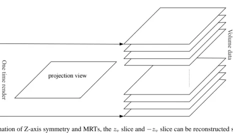
One time render
V
olume data
Fig. 6. Combination of Z-axis symmetry and MRTs, thezvslice and−zvslice can be reconstructed simultaneously. (b) Recycle (a) for the next projection view as illustrated in Fig. 5(b), until all projection views are
processed.
3.3. Z-axis symmetry and MRTs
From Eq. (8) we obtain that:
ttex(xv, yv, zv, θ) = 1−ttex(xv, yv,−zv, θ) (9)
And as shown by Eq. (7),stexis irrelevant with zv. These indicate that the mappings of volumezv slice and −zv slice are symmetric in t-axis of the texture. So either mapping of thezv slice or−zv slice is calculated, the other will be obtained, which saves some time computing the geometry mapping between slices to be reconstructed and projection views. Meanwhile, GPUs support Multiple Render Targets (MRTs), namely fragment shaders can have multiple fragment outputs. With the combination of symmetry and MRTs,zvslice and−zvslice as two targets can be rendered simultaneously as illustrated in Fig. 6.
These can be used together with CRTT by dividing the volume into two parts, and each part has a free frame, so the total slice number of each part isM/2 + 1. Each part forms a circle like Section 3.2. Two symmetric slices (like1andMslices,2andM−1slices) of the circles can be rendered simultaneously as illustrated in Fig. 7.
And note that: from Eq. (6) we obtain we = R+xvcosθ+yvsinθ, which exactly equates to U(x, y, θ), so the weightU can be gotten from w-buffer (we) [16], and it is unnecessary to compute again or store in a texture for looking up.
In this work, some other skills are also used to accelerate the speed of CT reconstruction. For one time reconstruction the source-center distanceR, and the discrete factor2π/N(N is the projection view number) are usually constants, all of these constants are computed when filtering on CPU which avoids traversing volume again after backprojection.
4. Experiments and results
Our experiments are performed on a 2.66 GHz dual-core Intel PC with 2GB RAM hosting a NVIDIA GeForce 8800GTX card. The projections are calculated from 3D Shepp-Logan phantom analytically. In
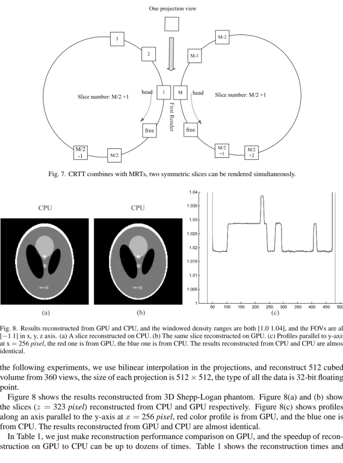
Slice number: M/2 +1 1 M/2 -1 M/2 free 3 2 head
One projection view
Slice number: M/2 +1 M/2 +1 M free M-2 M-1 head M/2 +2 First Render
Fig. 7. CRTT combines with MRTs, two symmetric slices can be rendered simultaneously.
50 100 150 200 250 300 350 400 450 500 1 1.005 1.01 1.015 1.02 1.025 1.03 1.035 1.04 (a) (b) (c) CPU CPU
Fig. 8. Results reconstructed from GPU and CPU, and the windowed density ranges are both [1.0 1.04], and the FOVs are all [−1 1] in x, y, z axis. (a) A slice reconstructed on CPU. (b) The same slice reconstructed on GPU. (c) Profiles parallel to y-axis at x=256 pixel, the red one is from GPU, the blue one is from CPU. The results reconstructed from CPU and CPU are almost identical.
the following experiments, we use bilinear interpolation in the projections, and reconstruct 512 cubed volume from 360 views, the size of each projection is 512×512, the type of all the data is 32-bit floating point.
Figure 8 shows the results reconstructed from 3D Shepp-Logan phantom. Figure 8(a) and (b) show the slices (z =323 pixel) reconstructed from CPU and GPU respectively. Figure 8(c) shows profiles along an axis parallel to the y-axis atx =256 pixel, red color profile is from GPU, and the blue one is from CPU. The results reconstructed from GPU and CPU are almost identical.
In Table 1, we just make reconstruction performance comparison on GPU, and the speedup of recon-struction on GPU to CPU can be up to dozens of times. Table 1 shows the reconrecon-struction times and
Table 1
Reconstruction performance comparison on GPU with applying techniques gradually
Technique Time Projections/s Speed
Just GPU 8.2s 43.9 1
T3.2 5.6s 64.2 1.46
T3.2–3.3 5.2s 69.2 1.58 Table 2
Performance comparison of various CT reconstruction systems. All values have been scaled to 360 projections and 5123 pixels, and scaled to a single processing unit-one CPU, one FPGA, one GPU, one Cell BE, and to 3.0GHz of GPU and Cell based algorithm [8]
Hardware Time Projections/s
Wiesent et al. [14] CPU 6.9 min 0.87
Exxim Computing Corp [6] GPU(8800GTX) 30 s 12
Li et al. [9] FPGA 40.2 s 9
Kachelrieß et al. [8] Cell BE (direct) 19.1 s 18.8 Cell BE (hybrid) 9.6 s 37.5 Xu and Mueller [16] GPU(8800GTX) 8.9 s 40.4
This paper GPU(8800GTX) 5.2 s 69.2
speedup on GPU with applying techniques gradually. T3.2 means the technique presented in Section 3.2, and T3.2–3.3 means combining all the techniques and skills presented in Section 3.2 and 3.3. The technique of symmetry and MRTs presented in Section 3.3 does not speed up remarkably due to the limitation of texture fill-rate, while the same method can be used in other hardware platform for acceler-ation. As shown in Table 1 the technique in Section 3.2 can speed up 1.46 times, together the speedup is 1.58 times, and the computation time is 5.2 s for reconstructing a 5123volume from 360 projections.
Table 2 shows CT reconstruction performance from different groups. All values have been scaled to 360 projections and 5123voxels.
5. Conclusions
With its powerful computing performance and programmable characteristic, modern GPU attracts more and more researchers and developers using it for generous purpose computing (GPGPU). It has many benefits than ASIC or FPGA in CT reconstruction, such as more cost-effective, flexible and easy to update. Since many operations in CT reconstruction are very similar to traditional computer graphics, GPU especially succeeds in 3D CT reconstruction. In this paper with the techniques of CRTT, the combination of symmetry and MRTs and other skills, the accelerating CT reconstruction generated an excellent result. Reconstructing a 5123volume from 360 views of the size of 512×512 just needs 5.2 s, and the results reconstructed from CPU and GPU are almost identical. Some of accelerating techniques such as CRTT can also be used in non-circular orbit CT reconstruction or other similar applications that need copy textures. The size of a 5123 volume in float type is 512 MB less than the on-board memory 768 MB of the NVIDIA GeForce 8800GTX card, therefore a 5123volume in float type can be reconstructed in one time. When reconstruct a volume more than 768 MB, the volume can be divided into some blocks and each block size is less than the on-board memory, If only one GeFore 8800GTX card is used, these blocks must be computed in turn. To reconstruct a whole volume in real time (as soon as complete scanning, reconstruction is just completed), larger on-board memory card or more PCs each hosting a card can be used.
Acknowledgments
This paper is supported by the Project for the National Basic Research Program (973) under Grant No. 2006CB705700, Changjiang Scholars and Innovative Research Team in University (PCSIRT) under Grant No. IRT0645, CAS Hundred Talents Program, CAS scientific research equipment develop program (YZ0642, YZ200766), 863 program under Grant No. 2006AA04Z216, the Joint Research Fund for Overseas Chinese Young Scholars under Grant No. 30528027, the National Natural Science Foundation of China under Grant No. 30672690, 30600151, 30500131, 60532050, Beijing Natural Science Fund under Grant No. 4071003.
References
[1] B. Cabral, N. Cam and J. Foran, Accelerated volume rendering and tomographic reconstruction using texture mapping hardware, in: Proceedings of the 1994 Symposium on Volume Visualization, Tysons Corner, Virginia, United States, 1994, pp. 91–98.
[2] L. Feldkamp, L. Davis, and J. Kress, Practical cone-beam algorithm, J Opt Soc Am A 1 (1984), 612–619.
[3] M. Frigo and S.G. Johnson, The design and implementation of FFTW3, Proceedings of the Ieee 93(2) (2005), 216–231. [4] N. Goodnight, R. Wang and G. Humphreys, Computation on programmable graphics hardware, Ieee Computer Graphics
and Applications 25(5) (2005), 12–15.
[5] http://ati.amd.com/. [6] http://www.exxim-cc.com/. [7] http://www.nvidia.com.
[8] M. Kachelrieb, M. Knaup and O. Bockenbach, Hyperfast Perspective Cone-Beam Backprojection, in: Nuclear Science
Symposium Conference Record, 2006, IEEE, 2006, pp. 1679–1683.
[9] J.C. Li, C. Papachristou and R. Shekhar, An FPGA-based computing platform for real-time 3D medical imaging and its application to cone-beam CT reconstruction, Journal of Imaging Science and Technology 49(3) (2005), 237–245. [10] NVIDIA, NVIDIA GeForce 8800 GPU Architecture Overview.
[11] J.D. Owens, D. Luebke, N. Govindaraju, M. Harris, J. Kruger, A.E. Lefohn and T.J. Purcell, A survey of general-purpose computation on graphics hardware, Computer Graphics Forum 26(1) (2007), 80–113.
[12] M. Segal, C. Korobkin, R.V. Widenfelt, J. Foran and P. Haeberli, Fast shadows and lighting effects using texture mapping, in: Proceedings of the 19th Annual Conference on Computer Graphics and Interactive Techniques, 1992, pp. 249–252. [13] H. Turbell, Cone-beam reconstruction using filtered backprojection: Link¨oping University, 2001.
[14] K. Wiesent, K. Barth, N. Navab, P. Durlak, T. Brunner, O. Schuetz and W. Seissler, Enhanced 3-D-reconstruction algorithm for C-arm systems suitable for interventional procedures, Ieee Transactions on Medical Imaging 19(5) (2000), 391–403.
[15] Y. X. Xing and L. Zhang, A free-geometry cone beam CT and its FDK-type reconstruction, Journal of X-Ray Science
and Technology 15 (2007), 157–167.
[16] F. Xu and K. Mueller, Real-time 3D computed tomographic reconstruction using commodity graphics hardware, Physics
in Medicine and Biology 52(12) (2007), 3405–3419.
[17] H. Yang, M. Li, K. Koizumi and H. Kudo, Accelerating Backprojections via CUDA Architecture, in: 9th International
Meeting on Fully Three-Dimensional Image Reconstruction in Radiology and Nuclear Medicine, Lindau, Germany, 2007,
pp. 52–55.
[18] L. Yu and X. Pan, A New Approach to Image Reconstruction in Cone-beam CT with a Circular Orbit, in: Proceedings of
the VIIth International Conference on Fully 3D Reconstruction In Radiology and Nuclear Medicine, Saint Malo, France,
2003.
[19] K. Zeng, E. Bai and G. Wang, A Fast CT Reconstruction Scheme for a General Multi-Core PC, International Journal of
Biomedical Imaging, 2007.
[20] J. Zhao, M. Jiang, T. Zhuang and G. Wang, An exact reconstruction algorithm for triple-source helical cone-beam CT,
Journal of X-Ray Science and Technology 14(3) (2006), 191–206.
[21] J. Zhao, Y. Lu, Y. Jin, E. Bai and G. Wang, Feldkamp-type reconstruction algorithms for spiral cone-beam CT with variable pitch, Journal of X-Ray Science and Technology 15 (2007), 177–196.