INTERNATIONAL DESIGN CONFERENCE - DESIGN 2004 Dubrovnik, 18-21 May 2004.
CAx/EDM Integration – Enabler for Methodical
Benefits in the Design Process
Holger Burr
1, Michael Vielhaber
2, Till Deubel
1, Christian Weber
1,
Siegmar Haasis
21
: Institute of Engineering Design/CAD, Saarland University, Saarbruecken, Germany 2
: DaimlerChrysler AG, Research and Technology, RIC/EP, Ulm, Germany
Keywords: CAx, EDM, design methodologies and practices,
assembly-oriented design, digital planning, structures in EDM
1.
Objectives
Over the past decade, the development of engineering information technology has led to a rapidly increasing number of process-supporting engineering systems. At the same time, substantial advances in engineering methodologies and practices are being introduced, often at an even greater pace than support systems. Closing this gap is paramount for optimal engineering processes, especially when developing complex products like such as passenger cars. This paper will take a look at today’s and tomorrow’s engineering practices, which are the key to further progress in reducing costs and time and optimising the product development process.
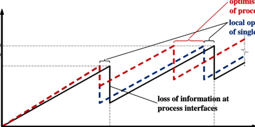
Major benefits can, however, only be achieved if based on a thorough concept of engineering system integration. Figure 1 visualises such benefits qualitatively. On the one hand, development time, which is one of the most crucial factors when developing products, can be cut in two ways. Firstly, local improvements in certain process steps within design and production planning can offer some benefits. Yet much more potential can be seen in the optimisation of the interfaces between the different stages of this process, as an enormous amount of information is lost when transferring data from one department to others: information quality and, as a result, product quality profit greatly from the reduction in loss of knowledge at the process interfaces.
loss of information at process interfaces loss of information at process interfaces
local optimisation of single process steps local optimisation of single process steps optimisation of process interfaces optimisation of process interfaces t kn o w le d g e gene ra ti o n design planning t kn o w le d g e gene ra ti o n design planning
The objective of this paper is to develop steps towards an integration concept capable of meeting the challenges of the development processes in place today and conceivable for tomorrow. Special attention will be paid to methods arising from the current trend towards relational, assembly-oriented design, exemplified by the topic of weld point definition within body-in-white product and process modelling, including the most crucial integration areas - CAD/EDM and CAP/EDM.
2.
The status quo
This section will take a brief look at the current situation in automotive engineering. Firstly, some IT developments in the designing and planning of products are presented. Secondly, the influence of new trends on the design process is addressed.
2.1 Historical development of engineering IT systems
Nowadays engineers deploy a multiplicity of supporting IT tools in their daily work. This includes all kinds of so-called CAx applications, with the “x” representing nearly every discipline in engineering; for example, CAD systems support the geometric modelling and design process, and CAP systems support the production planning process.
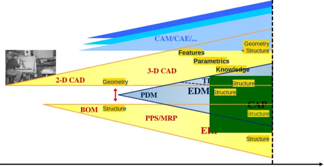
But when talking about integration concepts, it is necessary to be aware of the history of the development of such tools. Most of them have a long history, each of them having grown continuously in functionality and been optimised steadily over the past decades. That’s the reason for the current situation, which is depicted in figure 2. Some of these systems have been merged into bigger and more powerful tools (with “merged” not in all cases meaning “achieving better integration”, though), others still exist as custom tools for special applications. In some areas, the systems have formed architectures that interwork quite smoothly: the co-operation between CAD and FEM tools being an excellent example [Andersson1999]. But if a closer look is taken, we find that a lot of the systems on the market overlap each other and offer similar functionalities for certain applications, thus creating inconsistencies, redundancies, and confusion. Although many systems are bursting with functionality, gaps between the systems are not bridged systematically, resulting in a poor integration and interworking of all these IT islands.
BOM PPS/MRP
ERP
BOM PPS/MRPERP
2-D CAD 3-D CAD 2-D CAD 3-D CAD t PDM TDMEDM
PLM PDM TDMEDM
PLMCAP
CAM/CAE/... Features Parametrics Knowledge Features Parametrics Knowledge Geometry + Structure Structure Structure Geometry Structure Geometry Structure Structure Structure Structure Structure today todayFigure 2. Development of different IT systems
A good example in the case at hand is the administration of product structure data: for a long time this lay in the responsibility of BOM (bill of materials) systems. Now, the product structure can alternatively or additionally be modelled not only in BOM/ERP systems but also in EDM/PDM, CAD
or even CAP systems. This example shows that is essential to keep a good overview and assign clear areas of responsibility - even if this might lead to a completely revised field of work between the different IT system classes.
2.2 Trends in engineering methodology
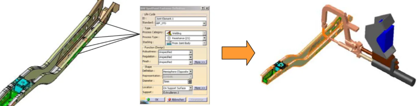
Many new trends impact the methodology of product development. Buzzwords such as “knowledge-based design”, “feature-“knowledge-based parametric design”, “the digital factory” or “assembly orientation” crop up. Some consequences - benefits as well as drawbacks - of these trends can be shown using the example of defining a weld point between two parts. State-of-the-art systems allow some characteristics such as the thickness and material of the weld points’ geometric “carrier”, the connected surfaces, to be read and checked automatically during weld point generation. Implicit knowledge tools can, for instance, prevent users from connecting two aluminium parts with standard resistance welding. Parameters such as the current or the holding time of the weld gun can be derived automatically by checking the parts’ thicknesses. But this example points to another problem. When using such IT tools, the design engineer defines enormous amounts of data which are very relevant for the following process of production planning and have, traditionally, belonged within this area. Now, production planners reap the consequences of this: not only do they need to be able to re-use data already included in the product model, they also have to add additional information (figure 3), e.g. an assignment to a special process plan or even a certain welding robot in the line. Another issue of importance when talking about weld points is the product structure level on which they are to be stored. Do they belong to each of the connected parts as an item of additional information, or do they only exist on the assembly level as a kind of part-spanning assembly information? This leads to the problem of managing assembly information in general, which is the focus of related research work presented in [Vielhaber2004]. Answering such questions is not easy, but it is necessary if all the process participants’ needs are to be met and the right architecture to handle and distribute the data properly is to be found.
Figure 3. Definition of weld points and re-use in process simulation
The example given for the definition and re-use of information about weld points clearly indicates the need for a properly structured data model in order to manage and utilize the information across the borders between the individual systems.
3.
Integration concepts and strategies
In the context of the situation described above, the focus of this paper will remain on the transition between digital design and digital production planning. Taking a look at the IT systems involved, the situation can be seen as portrayed in figure 4. On the one hand, there are CAD applications with their methods for the design department; on the other hand there are digital planning tools for the production planning process. The connecting layer in the middle represents the different kinds of data management systems.
Team data management (TDM) systems are said to be very close to the CAD systems: they are designed to support concurrent engineering in distributed design teams. Their counterparts in planning
processes are indicated by a so-called PPR database, whose task it is to handle and integrate the product, process, and resource data. In the middle lies the engineering data management (EDM) – system, which functions as an enterprise-wide archival and data management system. As discussed in [Burr2003], these EDM systems have incurred many problems since they were originally not designed to manage all the different kinds of data occurring in today’s development processes (see [Andersson1999]). As an additional layer, the ERP system is shown. It is bringing more and more influence to bear on the product development process and is linked closely to the EDM system. With a view to integration, all these different systems must be able to work seamlessly together, i.e. both in the horizontal direction and in the vertical direction, in order to facilitate the usage of data across processes as well as inside each individual partial process (cf. [Storga2001]). And a variety of concepts for effective integration are under discussion today.
FAKT / Am SECAM
Dialog
CATIA
MethodenSmaragd
DELMIA
MethodenPPR-Hub
EDM CAD CAP TDM PPR ERP Methodologies MethodologiesFigure 4. Integration of CAD and CAP applications into data management systems 3.1 Vertical integration of CAD and TDM/EDM
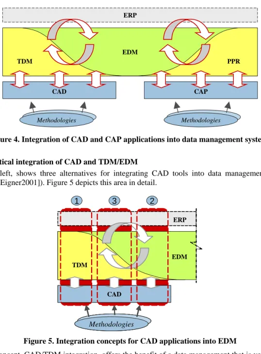
Figure 4, left, shows three alternatives for integrating CAD tools into data management systems (compare [Eigner2001]). Figure 5 depicts this area in detail.
CATIA
Methoden MethodenSmaragd
EDM CAD TDM ERP Methodologies Methodologies 1 3 2Figure 5. Integration concepts for CAD applications into EDM
The first concept, CAD/TDM integration, offers the benefit of a data management that is very close to the CAD applications, making optimisation with regard to the functionalities and data formats of the CAD system very easy. For example, this architecture promotes effective link management as well as archiving parametric designs such as skeleton models [Baer2001].
The second option is to focus more on an enterprise-wide data management, i.e. on storing all the data coming from CAx applications in a central EDM system. There are many examples in research projects that emphasise the need for such a solution, e.g. [Sellgren1996]. The great advantage of this concept lies in the information transfer to subsequent process steps, with striking improvements in change management and workflow procedures. Unfortunately the data formats are heavily restricted. Typically, the CAP applications should be flanged on the same EDM base, which often forces an organisation to procure from a single system vendor, minimising flexibility.
The third alternative is a combination of both approaches. Realising such a concept yields the greatest benefits, as the advantages of both extreme solutions can be combined. It enables effective storage of CAD-relevant data in early design stages, but it is also able to pass on the information needed by upstream process participants. Yet, while this alternative promises outstanding benefits, putting such a concept into practice is an extremely complex undertaking and would have to be accomplished by the company using it itself. Additionally, changes in working procedures are unavoidable and entire processes would have to be re-engineered.
3.2 Vertical integration of CAP and PPR databases
Within the last few years a new trend towards digital production planning tools has emerged. These tools support production planners in calculation, cost and time estimation, and detailed 3-dimensional process simulation. The concepts for integrating CAP systems with database applications are basically similar to those shown on the left-hand side of figure 4. Instead of TDM systems, we now find specialised databases (“PPR databases”) for the archival and management of planning data such as process plans, manufacturing layouts, different kinds of process charts, and simulations. The advantages and disadvantages of the different alternatives are identical to those in the CAD area. The difference here lies in the role of the geometric information. The exact geometry of the parts is needed only in very late phases of the planning process after a certain degree of maturity in product design is reached. During earliest planning stages, it is only the rough part geometry and dimensions and the so-called meta-data of the parts that are in of interest for the planner, e.g. the ID numbers, the material, the total number of weld points, and assembly information that deals with relations between two or more product components on different levels (cf. [Vielhaber2004]). This information should therefore be made available by product design as early as possible. In passenger car design, the information associated with a predecessor model may even be re-used.
3.3 Horizontal integration of CAD- and CAP-related data management
As mentioned, an integration of both areas in figure 4 in the horizontal direction offers the most gain from the enterprise point of view. This optimisation potential is high enough to justify the great effort called for in the realisation of such an architecture. The initial ideas for appropriate integration concepts have been introduced by the same authors in [Burr03]. Some of these have now been investigated further. The two most significant approaches are the best-in-class solution (figure 6) and the all-in-one concept (figure 7).
The first concept exploits the special functionalities of each application’s own databases, to ensure optimal support for the engineers in their daily work (focus on vertical integration). To achieve co-operative working between different departments (i.e. to accomplish horizontal integration), an integration layer with special kinds of data-objects that bring all these different types of information together is needed [Morales2003].
The second concept, using the all-in-one-approach, promotes an enterprise-wide working style; but in order to have a smooth-functioning concept, the user often needs to purchase all the applications from a single vendor (horizontal integration). And although the product portfolios of IT vendors today encompass a wide range of applications, their co-operation is sometimes still poorly performant and ineffective, which typically poses limitations on the vertical integration.
Data model
Product Process Resource
Data management
BOM DB PDM Analysis DB Planning DB Production DBs others
BOM CAD CAE CAP CAM ...
Inte-gration
Application
Linking element
Figure 6. Best-in-class-integration concept [Burr2003]
The resulting architecture achieved using the hybrid solution between the two extremes allows certain applications to employ their own data management while flanged onto the enterprise-wide EDM system. To do so, clear structures and workflows have to be formulated. Different kinds of data are generated at different points in time and in different areas within the development process. But as the degree of maturity in the product increases, these different structures converge more and more.
Data model
Product Process Resource
Data management
BOM DB PDM Analysis DB Planning DB Production DBs others
BOM CAD CAE CAP CAM ...
Linking element
Inte-gration
Application
Figure 7. All-in-one-integration concept [Burr2003]
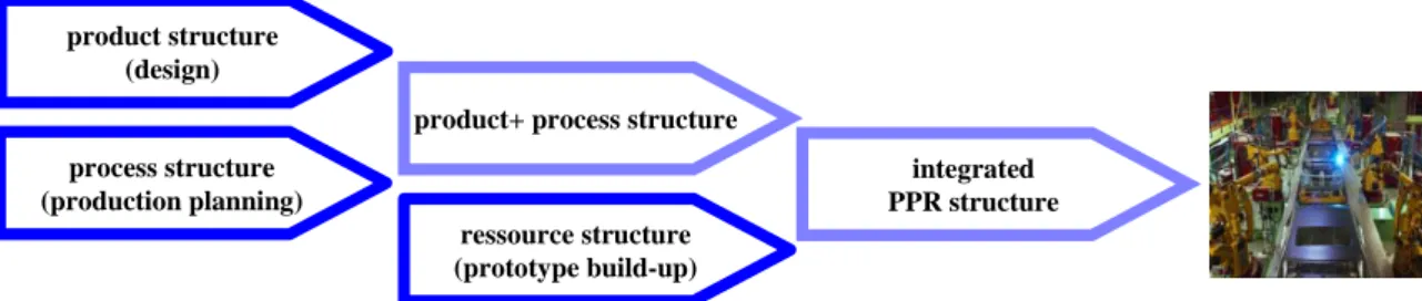
Figure 8 illustrates this behaviour in the area of interaction between development and planning. Whereas design engineers start creating their geometric structures with the CAD data, planners begin with their process-related structures in their own system environments. In this phase, their work is not largely dependent on the designers' geometric information. On the contrary, it is far more important for both groups to have more flexibility and freedom in their work. Of course, some limitations and boundary conditions have to be maintained, but neither product development nor process planning should be restricted too narrowly in their creative freedom.
At a certain time, these different structures have the necessary maturity to be merged and integrated. This can, for instance, be the release date or quality gate of a design stage. “Integration” in this context means a definition of the different structures in such a way that they can adapt easily at the very moment when they are brought together. As shown in figure 8, the result will be an integrated PPR structure, including data related to products, processes, and resources and, in the end, leading to the real production facility, which is no less than its reflection in the digital world.
product structure (design) process structure (production planning) ressource structure (prototype build-up) product+ process structure
integrated PPR structure
production
Figure 8: Different structures along the product development processes
First investigations with such structures and their behaviour have been carried out in a productive environment dealing with body-in-white-applications. So far, the results are quite encouraging.
4.
Application example: weld point
As set out above, a simple weld point affords a good example for the application of the architecture described and its different structures. The design engineer influences the planning process to a not inconsiderable degree when defining a weld point. The engineer's focus lies mainly on the geometric and functional perspectives, defining the weld point in the context of a special co-ordinate system with specific co-ordinate values and directions related to the product’s geometry. The process planner, on the other hand, is initially not at all interested in the exact position of the weld points. For process planning, the total number of weld points on an assembly is far more important in the early stages, as this affects the manufacturing layout (e.g. number of robots) and the related cost and time estimation. Only in later stages will the two structures from design and planning have to be brought together: for example, to be used in digital process simulations or concept validations, for the development and building of devices or for robot programming. Although coming from different structures, the weld point information in both structures will thus have to be linked. Within this process of merging the structures, data may have to be transferred from one structure to the other, without loss or inconsistencies. But when carrying out this step successfully, a complete structure with a certain degree of maturity is created, acting as a single contact point for subsequent departments or for all kinds of internal and external suppliers. On-going research work being done by the authors elaborates this approach, taking the different system concepts shown in figure 6 and 7 into account.
Weld points contribute to another interesting topic: variants. A great benefit in bringing together different structures is the ability to manage different variants and to re-use information. With regard to the definition of weld points, this would enable the re-use of certain groups of weld points in different contexts, without the necessity of generating the same data twice. For example, the connectors between the roof sheet and its framework could be used for variants with and without a sunroof. However, to re-use information, some technical clarification is required to define which parts of the structure could be re-used and which cannot. While the designer might be able to re-use the roof connectors, the planner may, however, see the need to diversify the manufacturing process for both variants (for reasons of technology, production figures, process complexity, quality, etc.) and therefore keep the structures separate.
This example clearly illustrates that such an integration concept is a complex architecture which calls for in-depth investigation in the area of interest, excellent preparation, and continuous optimisation in both the data models and the process workflows.
5.
Conclusions
Although the functionality of engineering systems is rocketing, they currently cannot sufficiently cope with the development of new engineering methods and influences arising from new trends within product and process development. Additionally, the data management systems and concepts of today fail to adequately support these innovative functionalities, their data formats, and the general trends in development processes.
The realisation and integration of new methods into existing and new system environments are often not taken into account. But what is the value of information that cannot be transmitted or managed appropriately and is therefore lost at the interfaces between the process stages? In addition to the optimisation of individual tool functionalities, integrated system architectures are needed, as they will be accompanied by new structures and process workflows. Putting effort into this will rapidly pay off through its catalyst function on design methodology benefits.
Initial investigations and implementations of the architectures discussed in this paper have been made in the body-in-white environment with encouraging results. The necessity of integrated structures is recognised by the users, and the first experiences made show that they are aware of the benefits that these new approaches can bring to their daily work, making it easier for them to accept the consequences of these process changes.
References
Andersson, K.: “A Design Process Model for Multiview Behaviour Simulations of Complex Products”, Proceedings of the ASME Design Engineering Technical Conference DETC’99, Las Vegas, USA, 1999. Baer, T. and Haasis, S., "Verkuerzung der Entwicklungszeiten durch den Einsatz von Skelettmodellen und der
Feature-Technologie", VDI-Berichte Nr. 1614, VDI-Verlag Düsseldorf, 2001, pp. 143-155.
Burr, H., et al., “Challenges for CAx and EDM in an International Automotive Company”, Proceedings of the International Conference on Engineering Design - ICED 03, Stockholm, 2003.
Eigner, M., Stelzer, S., “Produktdatenmanagement-Systeme”, Springer, Berlin, 2001.
Morales, H, “Assembly-Oriented Design komplexer Produkte in der Automobilindurstrie”, diploma thesis at the Institute of Engineering Design/CAD, Saarland University, Saarbruecken, 2003.
Sellgren, U., Hakelius, C., “Information Management in Product Development – Experiences from Six Swedish PDM Projects”, Proceedings of Produktmodeller 96, Linköping, 1996.
Storga, M., Pavlic, D. and Marjanovic, D., “Reducing Design Development Cycle by Data Management Within the Design Office”, Proceedings of the International Conference On Engineering Design - ICED 01, Glasgow, 2001.
Vielhaber, M., et al., “Assembly-oriented Design in Automotive Engineering”, Proceedings of theInternational Design Conference - Design 2004, Dubrovnik, 2004.
Holger Burr
Department of Engineering Design/CAD Saarland University Saarbruecken, Building 8.2 P.O.-Box 151150, 66041 Saarbruecken, Germany Tel: +49-681-302-3387
Fax: +49-681-302-4858
![Figure 6. Best-in-class-integration concept [Burr2003]](https://thumb-us.123doks.com/thumbv2/123dok_us/396904.2544379/6.892.181.777.109.408/figure-best-in-class-integration-concept-burr.webp)