Glyndŵr University Research Online
Conference Paper
Analysis of mechanical power flow in an electric drive
operating under vibration conditions
Ermolaev, A., Plekhov, A., Titov, D., Chakirov, R. and Vagapov, Y.
This is a paper presented at the 10th International Conference on Electrical Power Drive
Systems ICEPDS 2018, Novocherkassk, Russia, 3-6 October 2018.
Copyright of the author(s). Reproduced here with their permission and the permission of the
conference organisers.
Recommended citation:
Ermolaev, A., Plekhov, A., Titov, D., Chakirov, R. and Vagapov, Y. (2018) 'Analysis of
mechanical power flow in an electric drive operating under vibration conditions'. In Proc.
10th International Conference on Electrical Power Drive Systems ICEPDS 2018,
Abstract—This paper discusses the analysis of mechanical power flow in an electric motor drive operating under variation of conditions. The drive system vibration generates the oscillation in the supplied active power which can reduce performance of the system and increase the actual load on the shaft. It is shown that the vibration damper installation significantly decreases the oscillations in mechanical power flow on the motor shaft and improves characteristics of the system operation. The paper provide analysis of two models of the electric drive installed on the platform – the system which is quipped with vibration dampers and without.
Keywords—electric drive; vibration; damping; mechanical power; modeling; simulation
I. INTRODUCTION
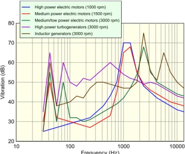
In many industrial applications, vibration in electric drives occurs due to the load variation and mechanical defects of motors [1],[2]. It is assumed that the power on the motor shaft developed to drive an industrial process is corresponding to the active power absorbed by the electric drive from the main grid. Therefore, the oscillations of the consumed active power are directly linked to the vibration occurred in the motor. In addition, the torque produced by an ac electric motor drive can fluctuate due to cogging torque effect, electromagnetic force in plain-pole machines, magnetic saturation of the rotor tooth zone, defects in controller, inverter, sensors, etc. whereas the mechanical defects contributing the torque oscillation are static and dynamic eccentricity of the rotor shaft, wear and play of the sliding or rolling bearings, fluffing of active stator steel packets etc. [3] A typical range of the torque pulsations related to electromagnetic processes is from 10 Hz to 10000 Hz [4]. The spectral densities of vibration for various electric motors are shown in Fig. 1.
Operation of electric drives utilised, for example, in the renewable energy generation systems is characterised by low frequency electromagnetic torque oscillations linearly related to the induction motor slip and grid current distortions. Apart from the torque oscillation and current distortion, mechanical load of electric drives is often stochastic which generates sharp changes in the power consumption. Such changes can significantly affect on the values of supplied voltage and, therefore, mechanical power on the motor shaft. This could also influence on the
operational performance of the other power devices connected in parallel to the electric drive [5].
It is known that the torque ripples on the motor shaft can be reduced by injection of compensating voltage/ current disturbance into the input supply voltage/current in order to control and, therefore, improve the motor performance. This approach requires a sophisticated tuning of the compensation signal in order to fully suppress the torque oscillations [6].
At present, there are two main types of vibration protection devices widely used in majority industrial installations. These are elastic based dampers and active electromagnetic antivibrators. Active electromagnetic antivibrators have adjustable parameters and can be controlled in accordance of a particular dumping algorithm. In general, the active dumper operation is based on two methods: electromechanical harmonic filters and magnetorheological fluid dumpers [7].
The inactive components of mechanical power flows in the system “motor drive–shaft–load–base” which are related to the motor vibration create an additional load on the system components: motor, shaft and actuator. At the design stage of an electric drive shaft system this load must be assessed to ensure the reliable operation. The value of vibration and, therefore, unexpected power fluctuations in the system can be significantly reduced using vibration
Analysis of Mechanical Power Flow in an Electric
Drive Operating Under Vibration Conditions
Yuriy Vagapov
Glyndwr University
Wrexham, UK Artem Ermolaev
Alekseev Nizhny Novgorod State Technical University
Nizhny Novgorod, Russia
Fig. 1. Spectral densities of vibration for various electric motors.
978-1-5386-4713-4/18/$31.00 ©2018 IEEE
Roustiam Chakirov
Bonn-Rhein-Sieg University of Applied Sciences
Sankt Augustin, Germany
Aleksandr Plekhov
Alekseev Nizhny Novgorod State Technical University
Nizhny Novgorod, Russia
Dmitriy Titov
Alekseev Nizhny Novgorod State Technical University
Nizhny Novgorod, Russia
This work was supported by the grant of the President of the Russian Federation for the State support of young Russian scientists (MK-590.2018.8).
dumpers. Due to this reduction, the motor drive hardware can be reduced in size and mass. It also contributes to the motor service life and improvement of electromagnetic and mechanical compatibilities.
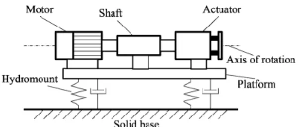
II. ELECTRIC DRIVE MECHANICAL POWER FLOW ANALYSIS The physical model of the electric drive is comprising the following elements: an electric motor, an actuator, and a shaft as it is shown in Fig. 2. The motor drive system is installed on a platform which is fixed to the rigid base. It can be seen that the motor rotates the actuator through the shaft which usually has the form of a rod. The actuator is mechanically linked to a load to provide rotation to a tool or other device. The actuator is controlled by the motor through the shaft connection.
Under normal operational condition, the moment or force pulsations in the system are related to the load variation. In general, the shaft transfers the motion to the actuator including the vibration component. In case of a gear box installed between motor and the actuator, its bearings’ fault and structural elements unbalance can bring an additional vibration. In the present model, it is assumed that the platform is rigid and fixed to prevent propagation of vibrations from one element of the system to another.
Mechanical forces produced from the motor shaft rotation are main source of vibration in electric drives [8]. The vibration-driving forces usually depend on the accuracy and quality of eclectic drive manufacturing. It also depends on the system degradation during operation.
The low-frequency vibration in electric drives is usually occurred due to the rotor unbalance and associated centrifugal force F and torque T. The system of equations below provides the description of the dynamic equilibrium of rotor which rotates around its axis of inertia:
(1) where F is the total force acting on the rotor, Fi is the i-th component of the total force acting on the rotor, mi is the mass of the i-th element of the rotor, yi is the displacement of the center of mass of the rotor element relative to the
1 1 1 1 1 0 0 n n i i i i i m m m i i i i i i i i i F F m y T T J m r
equilibrium position, T is the cumulative torque of the rotor forces, Ti is the i-th component of the torque acting on the rotor, Ji is the inertia of the i-th element of the rotor, ri is the distance from the center of mass of the i-th element to the axis of rotation of the rotor, φi is the angular displacement of the rotor.
In terms of generalised coordinates the system of differential equations can be represented as follows. The generalised coordinates are based on the rotation angle of the rotor (φ) and the vertical components of the force arising in the non-centred rotor (y) [9],[10].
(2) where mr is the mass of the rotor, m is the mass of the platform with the electric drive, Vr is the linear velocity of the center of mass of the rotor, g is the acceleration due to gravity, J is the moment of inertia of the rotor, Tr is the torque created by the stator winding, r is the radius of the eccentricity of the rotor shaft.
According to the mass center motion theorem the term Vr/dt summarises the acceleration of the center of mass and the harmonic vibrational motion at a given frequency of the oscillator.
(3) In general, under action of centrifugal forces an unbalanced motor rotor generates a driving force acting on the platform:
(4) where the first expression characterises the static imbalance of the rotor and the second characterises the dynamic imbalance.
The viscoelastic elements as shown in Fig. 3 generate compensatory forces to prevent the system from displacement from the equilibrium position and substantially suppress vibrations at high frequency. The parameters of the system with vibroelastic components, such as the stiffness coefficient C and the damping coefficient μ, are determined in [11]. Based on Newton's second law the following equations are obtained:
(5)
This system of equations gives a description of oscillation of forces and torques relatively to the equilibrium positions of the drive system shown in Fig. 3. The first equation is the motion of the shaft relatively to the fixed reference system along the vertical axis y. The second expression in the system (5) describes the motion of an unbalanced shaft in the horizontal plane in the radial direction z. The third expression is the rotational motion of an unbalanced shaft around the axis of rotation x.
sin sin r r r r r r V m m m m g dt J T m ry m gr
sin cos
sin sin r r r r r r m m y m r m m g J T m ry m gr
sin 0 sin 0 r r F F t T T t
sin cos sin cos sin sin r r r r r z z r rot r r m m y m r y Cy m m g m m z m r z C z J T m ry m gr Fig. 2. Motor drive system mounted directly on a fixed base.
The viscoelastic components attached to the base dissipate significant part of the pulsation power and linear oscillation power or convert it into platform motion to reduce the force effect of the shaft unbalance. In the case of transient occurred due to a rapid change in the static load of the motor, considerable portion of oscillations at high-frequency is absorbed by the shaft. If the controllable magnetorheological vibration dampers are used as viscoelastic components then the optimum adjustment of the parameters C and μ of the dampers can reduce the transient time [9, 10].
The measurement of force and torque oscillation on the rotor shaft can be done using vibration diagnostic equipment. The readings obtained form the measurement form a vibro-displacement diagram. The generated vibrating signal is analysed using Fourier transform and then represented as a spectrum to numerically determine the components related to active and reactive power:
(6) where Т, f are the period and the frequency of the investigated harmonic respectively, μ is the coefficient of coupling damping of rotor-bearing-stator contact, А is the amplitude of the investigated harmonic.
The power on the motor shaft can be divided into useful power flow Prot, the ripple power flow Qrot, the power of linear motion Qlin. If a viscoelastic base is included in the electric drive mechanical system then an additional component Qhm appears in the power flow equation, which characterizes the dissipation of oscillation energy in magnetorheological vibration dampers:
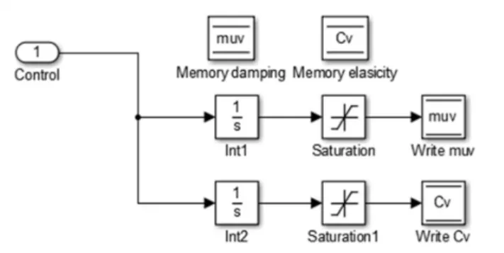
(7) III. VIBRATION DAMPING SYSTEM MODELLING Fig. 4 shows the simulation model build using the system of equation (5) for the physical model of an electric drive system installed on the base equipped with vibration dampers. This model takes into account mechanical power flows from the vibrating platform with an electric drive to the magnetorheological dampers and also the reverse action of viscoelastic forces. The operating principle of the magnetorheological damper control system is described in [12], [13].
System of equations (5) describes the physical model of the electric motor drive mounted on a fixed base. In this case, the parameters C and μ will represent the stiffness (C0) and damping (μ0) coefficients of the elastic drive
2 2 0 2 T r r m P y y y ydt A m f T
rot rot lin hm
S P Q Q Q
system, taking into account the viscoelastic properties of the structural components of the electromechanical drive system. Thus, to compare the dynamic properties of the first (on the fixed base) and the second (on the viscoelastic base) physical models, different initial data were selected:
The dynamic system simulation model and the control system software model are linked through analytically defined variables. Fig. 5 shows the simulation model of dynamic system of electric motor drive equipped with vibration dampers. The system parameters for both physical models are presented in Table 1.
IV. ANALYSISOF UNBALANCED ELECTRIC MOTOR DRIVE SYSTEM
The diagrams of angular velocity of the unbalanced rotor and radial force components acting on the motor bearings has been obtained from the models’ simulation. The total force acting on the electric drive installed on a fixed base is approximately 1.5 times greater than the same force acting in a system equipped with magnetorheological vibration dampers.
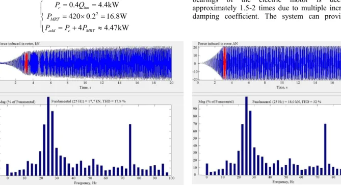
The estimation of mechanical power flows is analysed from the spectrum of force acting on the motor bearings. The obtained spectrums (Fig. 6 and 7) proves that majority of sub-harmonics were suppressed by both the dissipative action and elastic forces generated by magnetorheological dampers.
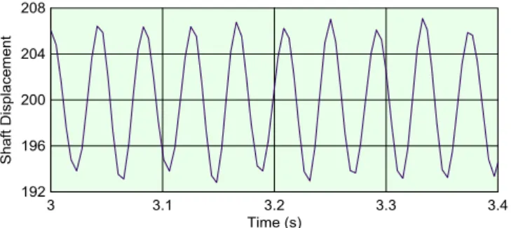
The evaluation of mechanical power flows can be obtained using (6) and (7). For this purpose it is necessary to obtain the vibration displacement signal of the electric drive relatively to the fixed base on which the dynamic system is installed. Diagrams of vibration displacement of the unbalanced rotor shaft in the radial direction obtained from the models’ simulation are shown in Fig. 8 and 9. The spectra obtained by the fast Fourier transform method are shown in Fig. 10 and 11.
The obtained values of the mechanical power flows components are given in Table 2.
0 0 0 0 N N×c Model #1: 10000 , 1 mm m N N×c Model # 2 : 100 , 10 mm m C C
Fig. 4. The block of the stiffness C and the viscosity μ variation for the magnetorheological vibration damper .
Physical parameter Symbol Value Measurement unit
Mass of the electric drive system located on a single platform
m 200 kg
Mass of the shaft mr 70 kg Electric motor torque М 4000 N·m Shaft rotation frequency n 1500 rpm Moment of inertia of the
shaft eccentricity J 22.6·10−3 kg·m2 Length of unbalanced the
shaft section l 0.6 m
Bending of the shaft Δr 4.7 mm Inertia tensor of the shaft [675.0 0 0;0 268.8 0;0 0 268.8], kg·m2·10−3
Checking the results the total values of the mechanical powers of each of the electric drive dynamic models coincided both with each other and with the rated power of the electric motor:
It should be noted that the effective operation of magnetorheological vibration dampers requires an external power source and a cooling system. Assuming that the cooling system power should be at least 0.4Qhm and each electromagnet of the magnetorheological transformer has an resistance Rhm = 420 Ohm, the required additional power is equal to: 1 2 2 4000 2 25 628.3kW 590 14 23 1 628kW 595 7 15 11 628kW n
rot lin rot hm rot lin rot hm
P M f S P Q Q Q S P Q Q Q
2 0.4 4.4kW 420 0.2 16.8W 4 4.47kW c hm MRT add c MRT P Q P P P P VII. CONCLUSIONThis article provide analysis of two dynamic models of the electric motor drive systems. The first model mathematically describes the performance of the electric motor drive which platform is fixed to the rigid base. The second model takes into account the vibration dampers installed between the drive system platform and the base. Operation of both systems are accompanied by vibrations occurred due to mechanical and electromagnetic processes.
The proposed simulation model provides investigation of dynamic processes in the electric motor drive installed on a single platform equipped with controllable vibration dampers. The magnetorheological vibration dampers have been selected for this purpose. The results obtained from the simulation shown that the total force acting on the bearings of the electric motor is decreased by approximately 1.5-2 times due to multiple increase in the damping coefficient. The system can provide a very
Fig. 6. The diagram and spectrum of the inertial force acting on the electric motor bearings in the dynamic system of the electric drive mounted on a fixed base.
Fig. 5. Simulation model of a dynamic system of electric motor drive with vibration dampers.
Fig. 7. The diagram and spectrum of the inertial force acting on the electric motor bearings in the dynamic system of the electric drive mounted on a viscoelastic base.
efficient damping even under a significant increase in vibration displacement (by 10-12 times).
The sums of the mechanical power flows of both electric drive dynamic models correspond to the rated power of the motor Pn = 628 kW.
A comparison of the spectrograms of the two dynamic drive systems has proved that the system equipped with
magnetorheological vibration dampers absorbs about 50% of parasitic mechanical energy flows of the electric motor drive mainly taken from the power of the linear vibration displacement of the system.
REFERENCES
[1] V.G. Gerasimov (ed.), Electrotechnical Handbook, Vol. 2: Electrotechnical Products and Devices, 9th ed. Moscow: MPEI, 2003.
[2] A.P. Petrov, Distributing Gearboxes. Kurgan: Kurgan State University, 2014.
[3] A.V. Barkov, and N.A. Barkova, Vibration Diagnosis of Machinery
and Equipment. Analysis of Vibration. Study Guide. Saint
Petersburg: SPbGMTU, 2004.
[4] I.G. Shubov, Noise and Vibration of Electric Machines. Saint Petersburg: Energoatomizdat, 1986.
[5] I.V Belousenko, and V.F. Yugay, “Evaluation of the influence of the main parameters of industrial power supply systems on the stability of nodes of electric load,” Industrial Energy, no. 10, pp. 31-33, 2002. [6] T. Su, S. Hattori, M. Ishida, and T. Hori, “Suppression control
method for torque vibration of AC motor utilizing repetitive controller with Fourier transform,” IEEE Trans. Industry Applications, vol. 38, no. 5, pp. 1316-1325, Sep.-Oct. 2002. [7] B.A. Gordeev, A.N. Osmekhin, S.N. Okhulkov, and A.S. Plekhov,
“Elimination of hysteresis effects in ferromagnetic cores of electromechanical transducers of hydraulic vibro-supports,” Vestnik IEEU, no. 5. pp. 64-68, 2013.
[8] B.A. Gordeev, S.N. Okhulkov, A.N. Osmehin, and A.S. Plekhov, “Measurement of torsional moments on shafts of electrical complexes connected by magnetorheological clutch, frequency method,” NNSTU Transactions, no. 3, pp. 65-70, 2017.
[9] A.I. Ermolaev, S.N. Okhulkov, A.S. Plekhov, and D.Y. Titov, “Semiconductor converter for field magnets of hydromounts with a magnetorheological transformer,” in Proc. Int. Conf. on Power, Instrumentation, Control and Computing, Thrissur, India, 9-11 Dec. 2015, pp. 1-3.
[10] S. Guo, S. Yang, and C. Pan, “Dynamic modeling of magnetorheological damper behaviors,” Journal of Intelligent Material Systems and Structures, vol. 17, no. 1, pp. 3-14, Jan. 2006. [11] B.A. Gordeev, A.V. Leonteva, A.N. Osmekhin, S.N. Okhulkov, and
V.V. Bugajsky, “Experimental investigations of the complementary effects in the synchronization of two motors on an elastic base,”
Bulletin of Machine Building, no. 6, pp. 39-42, 2013.
[12] A.I. Ermolaev, S.N. Okhulkov, A.S. Plekhov, and D.Y. Titov, “Implementation of a control system for hydromounts with a magnetorheological transformer on a FPGA,” in Proc. Conf. Actual Problems of Electric Power Industry, Nizhny Novgorod, Russia, 2016, pp. 136-141.
[13] A. Ermolaev, A. Plekhov, D. Titov, A. Anuchin, and Y. Vagapov, “Adaptive control of magnetorheological fluid damper,” in Proc. 52nd Int. Universities Power Engineering Conf. (UPEC-2017), Heraklion, Greece, 28-31 Aug. 2017, pp. 202-207.
Fig. 8. The diagram of the shaft displacement relatively to the fixed reference system in the electric drive installed on the fixed base.
Fig. 9. The diagram of the shaft displacement relatively to the fixed reference system in the electric drive system installed on the viscoelastic base.
Mechanical power flows
component Symbol
Value for physical model
#1, kW
Value for physi-cal model #2,
kW Useful power Prot 590 595
Power of linear perturbations Qlin 14 7 Torque ripple power Qrot 23 15
Power dissipated by damping
forces Qhm 1 11
TABLE II. OBTAINED VAUESOFTHE MECHANICAL POWER FLOW COMPONENTS
Fig. 10. The spectrum of the shaft displacement relatively to the fixed reference system in the electric drive system installed on the fixed base.
Fig. 11. The spectrum of the shaft displacement relative to the fixed reference system in the electric drive system installed on the viscoelastic base.