Tribology in Industry
www.tribology.fink.rsAnalysis of Failure Causes and the Criticality Degree
of Elements of Motor Vehicle’s Drum Brakes
D. Ćatića, J. Glišovića, J. Mikovića, S. Veličkovića
aUniversity of Kragujevac, Faculty of Engineering, Sestre Janjic 6, Kragujevac, Serbia.
Keywords: Reliability FTA FMECA Motor vehicles Drum-brake A B S T R A C T
The introduction of the paper gives the basic concepts, historical development of methods of Fault Tree Analysis - FTA and Failure Modes, Effects and Criticality Analysis - FMECA for analysis of the reliability and safety of technical systems and importance of applying this method is highlighted. Failure analysis is particularly important for systems whose failures lead to the endangerment of people safety, such as, for example, the braking system of motor vehicles. For the failure analysis of the considered device, it is necessary to know the structure, functioning, working conditions and all factors that have a greater or less influence on its reliability. By formation of the fault tree of drum brakes in braking systems of commercial vehicles, it was established a causal relation between the different events that lead to a reduction in performance or complete failure of the braking system. Based on data from exploitation, using FMECA methods, determination of the criticality degree of drum brake’s elements on the reliable and safe operation of the braking system is performed.
© 2014 Published by Faculty of Engineering
Corresponding author: Dobrivoje Ćatić, full professor University of Kragujevac, Faculty of Engineering, Sestre Janjic 6, Kragujevac, Serbia E-mail: caticd@kg.ac.rs 1. INTRODUCTION
Reliability analysis of technical systems is based on failure analysis of their elements. For failure analysis of technical systems and their components, a number of methods have been developed. The Fault Tree Analysis (FTA) and Failure Modes, Effects and criticality Analysis (FMECA) are most commonly used from all methods [1-3].
FTA is a deductive method where at first the so-called top event, which in technical systems represents a failure, and then the possible causes of this failure inside the system are
analysed. The basis of the fault tree represents a transformation of physical systems to structural logic diagrams.
The FTA method was invented and developed in 1961 by H.A. Watson at Bell Telephone Laboratories in connection with a US Air Force contract for a safety study on the Minuteman Launch Control System [4-5]. After the initial
work at Bell Telephone Laboratories,
development of the fault tree continued at the Boeing Company, where the technique was applied to manned aircraft and simulation techniques were used extensively. In the seventies, the method was used in particular in
R E S E A R C H
determination of effects of different failure modes of technical systems. This method dates
from November 9th, 1949, as an official
document [7]. Application of FMEA in
automotive industry projects followed no sooner than in the second half of the 1980's and it was related with introduction of quality regulations Q-101 by American Ford Company.
FMEA is a procedure for evaluation of reliability of a technical system that may be applied in all phases of its lifetime. FMEA is generally an inductive method. It is based on consideration of all potential failures of constitutive parts of the system and effects they have on the system. Criticality Analysis (CA) is a procedure for evaluation of criticality rating for all constitutive parts, where, by criticality, a relative measure of item’s failure modes influence on reliable and safe operation of the system is meant. Joint FMEA and CA analysis are called Failure modes, effects and criticality analysis - FMECA. According to previous considerations, application of FMECA based on exploitation data is founded on the assumption that the intensity of all failure modes of system elements is constant, which is valid for
electronic systems [8]. This assumption
considerably simplifies the procedure for criticality assessment. However, application of this methodology in cases when failure intensity is a function of time may lead to distortion of real picture of elements’ criticality. A proposal for procedure of quantitative FMECA of machine system’s elements, originating from modification of the existing method, is given in paper [9]. The application of these methods gives the best results in the design phase because it enables removal of causes of the potential failure of system‘s elements or reducing the consequences of failure with the lowest costs.
2. STRUCTURE AND FUNCTIONING OF DRUM
BRAKES
Performing detailed analysis of the causes and failure modes of the observed object requires knowledge of the structure, functioning modes and the relationship among the constituent elements. Only a full understanding of the functioning of the system and its elements, as well as knowledge of their mutual relationships, allows the implementation of logical analysis that defines the necessary and sufficient conditions for the appearance of the object's failure.
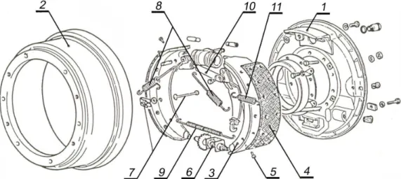
Figure 1 [10] shows the parts of the drum brakes
that are mounted on the rear wheels of light commercial vehicle manufactured by "Zastava Trucks" in Kragujevac. Similar solutions of drum brakes are applied also on the front wheels. The difference between these constructions is in existence of a lever mechanism on the rear brakes, which allows the use of these brakes as the parking (auxiliary) brakes.
Drum brake is composed of mobile and immobile elements. Immobile elements are via backing plate (1) attached to the supporting structure of the vehicle, while moving parts (drum (2)) are connected to wheel hub. Friction elements of drum brakes are two symmetrically placed brake shoes and drum. During brake activation, brake shoes snuggle up with the drum and thus the car's kinetic energy is converted into heat, i.e. braking of the vehicle is performed. Drum brakes’ shoes are composed of a metal carrier part (3) and friction lining (4). The connection between the metal part and friction lining can be achieved by riveting (rivets
Fig. 1. Main parts of rear drum brakes: 1 – Baking plate, 2 - Drum, 3 – Brake shoe, 4 – Shoe lining, 5 - Rivet, 6 – Brake adjuster, 7 - Elements for holding the shoes, 8 - Shorter return spring, 9 - Longer return spring, 10 - Lever mechanism of the parking brake 11 - The return spring.
(5)), bonding (only by glue or by glue and a chemical process during vulcanization), or by a combination of these two methods, depending on the brake’s type. Brake shoes of simplex brakes are supported at lower ends, and in particular, at drum brakes shown in Fig. 1, on clamping of the brake adjuster (6). Activation forces act at the upper ends of shoes and break them apart, which results in friction force between the drum and brake linings. Main task of elements for holding shoes (7) is to ensure the specific position of shoes, so during brakes activating, the brake is as quickly and better brought into contact with the drum. An integral part of the elements for holding the shoes is the spring that allows the movement of shoes with minimal resistance. Return springs (8) and (9) hold the shoes attached to the supports and during releasing they return shoes to the starting position. Especially is evident the importance of for the return spring for safe releasing, i.e. complete separation of the elements of the friction pair during the periods when the vehicle must not be braked (when it is in driving situation).
Drum brakes can be activated hydraulically or mechanically. If the hydraulic transmission mechanism is used for the service brake on motor vehicles, activation of shoes is performed by hydraulic cylinders. Braking torque is proportional to the activation force of the brake, i.e. the operation pressure and to the diameter of the brake cylinder. The brake cylinder is a screw-connected to the baking plate (1), which is usually made in sheet metal forming processes
with a relatively strong relief, resulting in a higher stiffness of the element.
Rear brakes of the vehicles represent the executive mechanisms of the service and parking brake of the vehicle. Activation of shoes for the parking brake is done via the lever mechanism (10). After termination of the parking braking, spring (11) returns a lever mechanism for activation of the drum brake in the position prior to activation. The liver mechanism of the parking brake on the wheel must be independent of the mechanism that is used for service braking, especially should not interfere with this basic function of the brakes in any way.
It is very important that the clearance between the drum and brake lining at drum brake should be properly adjusted. The large clearance increases travel of the command pedal of service brake and extending the system response time, which is adversely in terms of traffic safety. Furthermore, a large clearance increases travel of pistons in brake cylinders, increasing the wear of pistons, cylinders and sealing elements. There are several methods for the clearance
regulation. The required travels for
compensation of wear brake linings of shoes for passenger vehicles are small, so the regulation of clearance can be made by the cams, sliding elements on the shoes’ ribs or through specially made brake cylinders. The relatively high wear of brake linings is allowed in commercial motor vehicles, and it is necessary to provide greater movement of shoes. One way for clearance
distribution law on brake linings depends on several factors, but primarily on structural solutions of drum brakes (simplex, duplex), the stiffness of the drum, shoes and linings, support systems of shoes, shape of shoes’ abut surfaces (the consent shape with the drum) etc.
Construction solutions of drum brakes influence on distribution of braking torque, i.e. the surface pressure on shoes. In simplex brake, due to
uneven pressure distribution on contact
surfaces, lining’s wear of leading shoe
(activating force and friction force on this shoe lining have the same direction) is significantly larger than at the other (trailing) shoe.
The elastic deformation of the drum has significantly influence on pressure distribution on the arc length of the friction lining. In addition, the deformation of the drum can reduce developed braking torque over two times. This is a direct result of the fact that one part of shoe’s movement "consumes" on drum’s deformation, which reduces the activation force acting on shoes. The real activation force of leading shoe is almost three times smaller during elastic deformation of drum.
Adjusting the position of shoes to the drum, and therefore, more uniform wear lining, is provided via the sliding supports. Surfaces on which shoes support, may be parallel to the vertical axis of the wheel or can be oblique. It should be noted that both solutions are often used and that in both cases can be achieved corresponding pressure distribution along the lining’s length. In addition, the shoes have two degrees of freedom: translation in a radial direction and rotation.
for complex events. Among the symbols used for basic events most commonly used is the circuit, which signifies the state of an element of the system conditioned by its characteristics, and rhomb, which indicates an undeveloped event. Logical symbols in the fault tree signify mutual conditionality and correlation of lower and higher levels events. For example, the "OR" logic gate produces output if one or more input events are happened. In contrast, "AND" logic gate produces output only if all input events occur. Figure 2 shows the fault tree of drum brakes. The peak event in the fault tree, “failure of the drum brake”, implies a complete or partial brake’s failures. The manner of defining the peak event enables recording of the highest number of potential failure modes of drum brake’s elements. Total failures of drum brake occur when the braking torque cannot be achieved on the brake, and they rarely happen. In the case of partial failures, the operating characteristics of brakes are significantly deteriorated. This manifests through the reduction of achieved braking torque on the brake, uneven braking or delayed response of brakes. Failures that lead to reduction of the braking torque are usually called friction failure. They can be permanent and transient.
Permanent friction failures could occur due to wear of the friction surfaces of drums and linings, inhomogeneity of the lining material (presence of hard inclusions), occurrence of cracks and falling out of lining’s pieces, dirty or greased friction surfaces etc.
drum is creating dust that, in case of damage of the brake cylinder’s sealing cap can reach the sliding surfaces of elements of this assembly and thus deteriorate the friction conditions.
The presence of hard inclusions in the brake shoe linings, in addition of reduction of the friction coefficient between the lining and the drum, causes the abrasive wear of friction surface of drum. As a result, there is damage of drum’s surface and reduction of the braking torque. Furthermore, occurrence of cracks and falling out pieces of lining leads to deterioration of operation characteristic of brakes.
During brake operation, a crust of soot is forming on friction lining and it has significantly different properties than the base friction material. This significantly reduces the friction coefficient of braking lining. Furthermore, the oil leakage from the brake cylinders due to nonhermetic leads to greased shoe lining and reduction of the friction coefficient. In case of greased lining, regeneration of operating capability of brake is done first by removing the cause of failure by replacing the sealing rings of the brake cylinder or all cylinders, and then by performing the interior cleaning of brakes and grinding of the friction surface of lining [12]. Uneven braking represents a special type of permanent friction failures in which, in addition to reduction of the braking torque, the jitter of brakes during the braking is much expressed. Brakes jitter is caused by uneven distribution of pressure on arc length of the lining. There are several reasons for this, such as: geometric deviations of friction surfaces, mechanical damage of the friction elements, baking plate failure or failure of elements for holding the shoes.
This starts breaking even when brakes are not activated, which is especially dangerous for traffic safety. Furthermore, there is a damage of the friction surfaces of lining and the drum in the form of deep furrows.
The response time delay of the drum brakes, from the aspect of failures of brake’s elements, occurs due to non-adjustment of the clearance between lining and drum. This intermediate event occurs if, due to failure of elements of the adjust mechanism, this device does not perform its function.
Transient friction failures may occur due to wetting inside the brake with water, due to a long-lasting braking while the vehicle is moving on a downhill or due to incomplete brake release when brake is not activated.
The presence of water in the interior of the brake results in a decrease of the friction coefficient and the achieved braking torque. During braking, due to the heating of brake’s elements, comes to water evaporation and the return working capacity of the brake.
In the case of long-term braking during vehicle moving downhill, the heat produced by converting the car's kinetic energy is greater than the heat that brake’s components submitting to the close surroundings. Therefore, the high operating temperature of all elements of drum brakes is occurred. The high operating temperature leads to decrease of the friction coefficient between the lining and drum. Phenomenon of deterioration of frictional properties of the material, due to the increase in temperature, is known as "fading" [13]. This phenomenon is especially noticeable when brakes have non-metal part made of asbestos.
The frictional linings cooling leads to accomplishment of the moderate level of operating temperatures and frictional properties
are returned and friction coefficient is
"restored". Because of that, these and similar forms of defects are called transient failures. The high operating temperature, in addition to the impact on friction coefficient affects also on the deformation of elements (oval shape of the drum, bending of shoes), cracks of the drum, changing the characteristics of the material (loss of elasticity of return springs), accelerated aging of sealing elements of the brake cylinder, etc. Incomplete disengagement of drum brakes
caused by failures in the transmission
mechanism of the service or the parking brake or by failure of return springs of the brake shoes, depending on the degree of achievement, leads to permanent braking of vehicles, increasing the operating temperature of brake, decreasing the friction coefficient and rapid wear of friction elements.
Since the regular operation of brakes is in indirect way affected by failures of elements of transmission mechanisms, which represent separate entities in the braking system, fault tree shown in Fig. 2 is not independent. This conclusion can be also made over an undeveloped event "Fouling of friction surface", which in extreme cases can be a consequence of the oil leakage from the brake cylinders, i.e. because of the nonhermetic of these cylinders. As already mentioned, the role of return springs is to ensure safe separation of friction surfaces during periods when the brake is not activated. Failures of return springs of drum brakes, such as spring break, elasticity loss or fallout from the tray, lead to improper position of shoes and continuous contact between the shoe linings and drum.
4. FAILURE MODE, EFFECTS AND CRITICALITY
ANALYSIS OF DRUM BRAKES’ ELEMENTS
Analysis of the modes, effects and criticality of failures of technical systems’ elements can be done qualitatively or quantitatively, depending on whether the data on failure intensity of elements are known [5]. In case of mechanical elements, when failure intensity is a function of
time, for determination of the criticality of the j
-th failure modes of i-th element for category of the failure effect, k, the expression is used [9]:
( )
( )
sri i k ij ij k ij t t C =α ⋅β ⋅ (1)where αij is a relative rate (frequency measure)
of failure mode j of element i
(0≤ ≤1, ∑ =1
j ij
ij α
α ), βij( )k is conditional
probability that failure mode j of element i will cause category k failure effect according to the adopted classification (values are taken from
Table 1, according to recommendations from [6,
8], ti is operating time of element i and tsri is
mean operating time until failure of element i
occurs.
Table 1. Values of conditional probabilities Degree of occurrence of the k-th
failure effect category
( )k ij
β [-]
Certain event 1
Probable event 0.1 ... 1
Most probably would not happen 0 ... 0.1 Practically doesn’t happen 0
To be able to perform analysis of the effects within FMECA, it is necessary to all the failure effects of the observed object classify by categories. The analysis of the final effects of potential failure modes of drum brakes’ elements has shown that they can be classified into two categories:
• k.1 - The effects in cases where the safety of
persons and vehicles is compromised, due to significantly reduced performance of the brake system (disastrous consequences for the vehicle and/or driver and other traffic participants);
• k.2 - Reducing the achieved braking torque
on the brake (Decrease of the realized braking torque on the brake can occur due: deformation of the drum or shoes, wear, filthiness or inhomogeneities of brake linings, decrease of the friction coefficient due to the high temperature of friction surfaces, etc.).
Determination of the criticality of drum brakes’ elements is performed based on the data given in Table 2.
holding Extraction Insufficient efficiency N.29 N.30 0.008 0.009 0.6 0.3 k.2 k.2 70 90 Return spring of the shoe 51302 51303 Spring cracking Insufficient elasticity Fallout of spring N.06 N.15 N.29 0.01 0.009 0.009 0.8 0.5 0.8 k.2 k.2 k.2 70 90 70 876.9 14.62
Adjust mechanism 51304 Cracking of elements Damage of the coil of shoes support Insufficient efficiency N.06 N.07 N.30 0.001 0.001 0.02 1.0 0.4 0.4 k.2 k.2 k.2 70 130 60 881.6 14.69
Backing plate 51305 Cracking of backing plate Insuff. tightening of the nuts Damage of screw connection
N.06 N.31 N.32 0.0005 0.002 0.001 1.0 0.2 0.4 k.1 k.1 k.1 800 20 200 897.5 14.96 Drum 51306 Cracking
Oval shape - irregular shape Traces on the work surface Wear of work surface
N.06 N.24 N.64 N.77 0.005 0.02 0.4 0.575 0.8 0.6 0.7 1.0 k.1 k.2 k.2 k.2 180 15 200 300 253.7 4.23 Lever mechanism of the parking brake on the wheel
52206 Fracture of the fastening parts Get jammed N.32 N.36 0.005 0.005 1.0 0.4 k.1 k.2 130 90 892.1 14.87 Return spring of the lever mechanism 52207 Spring cracking Insufficient elasticity Fallout of spring N.06 N.15 N.29 0.01 0.009 0.009 0.2 0.1 0.2 k.2 k.2 k.2 70 90 70 876.9 14.62
Table 3. Criticality of elements’ failure modes without taking into account the effects. No. Code Element’s
name
Failure mode Eff.
name α [-] β [-] sr t [h] i t [h] Criticality ( )k ij C [-]
1 51312 Shoe lining Lining wear k.2 0.880 1.0 1.550E+03 1 0.5677E-03 2 51306 Drum Working surface wear k.2 0.575 1.0 4.230E+03 1 0.1359E-03 3 51306 Drum Traces on working surface k.2 0.400 0.7 4.230E+03 1 0.6619E-04 4 51312 Shoe lining Lining filthiness k.2 0.010 1.0 1.550E+03 1 0.6452E-05 5 51312 Shoe lining The lack of elasticity - the
hard inclusions k.2 0.010 0.8 1.550E+03 1 0.5161E-05 6 51312 Shoe lining Lining detach (crack.
rivets)
k.1 0.005 1.0 1.550E+03 1 0.3226E-05 7 51312 Shoe lining Lining cracking k.1 0.005 1.0 1.550E+03 1 0.3226E-05 8 51306 Drum Oval shape – irregular
shape
k.2 0.020 0.6 4.230E+03 1 0.2837E-05
9 51306 Drum Cracking k.1 0.005 0.8 4.230E+03 1 0.9456E-06
10 51302 Return springs of shoe
By processing of the acquired data and by using the computer program, output lists are gained for degree of criticality of the drum brakes’ elements failure modes without taking into account the effects (Table 3), degree of criticality of the drum brakes’ elements with taking into account the effects (Table 4) and degree of criticality of final failure effects of the drum brakes’ elements (Table 5).
To assess the degree of criticality of failure modes of drum brakes’ elements, a total of 28 different failure modes of elements were examined. Output program list for the degree of criticality of failure modes of elements regardless of the effects contains the failure modes ranked according to criticality. Since the failure modes of elements are aligned in descending order by criticality, the first part of this list is interesting for analysis. Therefore, and because of lack of the space in the paper, only the initial part of the output list of the program is given in Table 3. Based on the results in Table 3, the biggest criticality has worn of brake shoe’s lining. Second and the third place take failure modes of the drum, followed by the remaining failure modes of shoe’s lining and drums. Criticality of failure modes of the remaining elements is more than a thousand times smaller than the criticality of most critical failure modes of drum brakes’ elements.
Table 4. Criticality of elements with taking into account the effects.
a) Criticality by effects k.1 No
.
Code Element’s name ( )k i
C [-] 1 51312 Shoe lining 0.6452E-05 2 51306 Drum 0.9456E-06 3 52206 Lever mechanism of
parking brake
0.3362E-06 4 51305 Backing plate 0.8690E-07 b) Criticality by effects k.2
No. Code Element’s name ( )k i
C [-] 1 51312 Shoe lining 0.5794E-03 2 51306 Drum 0.2050E-03 3 51302 Return spring of shoes 0.1347E-05 4 51301 Elements for holding
shoes
0.1059E-05 5 51304 Automatic brake
adjuster
0.6399E-06 6 52207 Return spring of lever
mechanism
0.3215E-06 7 51311 Brake shoe 0.2199E-06 8 52206 Lever mechanism of
parking brake
0.1345E-06
Based on Table 4, the greatest criticality for both categories of effects has shoe’s lining. The drum is in second place. Criticality of the next element in the sequence is substantially smaller than the criticality of shoe’s lining (for first category of effects is about 20 times, and for a second category of effects is over 430 times smaller). Table 5. Criticality of final failure effects
No. Final effect Ck[-] Rel. crit. % 1 k.2 0.7880E-03 99.02 2 k.1 0.7820E-05 0.98 According to Table 5, the distribution of failure modes with the category effect one is infinitesimal in relation to the presence of failure modes with the category effect two. Pareto analysis of criticality of elements for effect two is given in Fig. 3 in order to illustrate the criticality of elements. Since the representation of failure modes for the first category of effects is negligible, Fig. 3 illustrates also the overall criticality of the elements. The highest relative criticality of 73.53 % has shoes linings. In second place by criticality is the drum with 26.01 %, while the other seven elements take only 0.46 %.
0.46
75.53 26.01
The shoes lining Drum The other elements
Fig. 3. Percentage of criticality of failure modes of drum brakes’ elements for the category effect two.
5. CONCLUSION
By forming the fault tree for drum brakes as elements of braking systems of motor vehicles, in addition to a better understanding of this important assembly from the point of failure, it was recorded most of the failure modes of the constituent elements. The basis for quantitative analysis of the modes, effects and criticality of elements’ failure is obtained by collecting the remaining required data related to failures of elements of researched assembly. Calculation of the criticality of failure modes of elements and
of drum brakes can be used for any mechanical system. The combined use of FTA and FMECA is especially suitable for failure analysis of complex systems. Namely, by analysing modes, effects and criticality of failure at the level of assembly, the critical entireties of the system to which special attention should be paid during formation of the fault tree can be determined.
REFERENCES
[1] B. S. Dhillon: Design reliability, fundamentals and applications, Department of Mechanical Engineering, University of Ottawa, Ottawa, Ontario, Canada, CRC Press LLC, 1999.
[2] B. Bertsche: Reliability in automotive and mechanical engineering. VDI-Buch, Springer-Verlag, Berlin Heidelberg, 2008.
[3] D. Catic: Reliability in development of mechanical systems, Faculty of Mechanical Engineering, Kragujevac, 2010.
[4] C. Ericson: Fault Tree Analysis – A History, in: Proceeding of the 17th International System
[8] Mtain Inc.: Reliability, maintainability, logistics support, engineering services, reliability failure modes, effects and criticality analysis, from http://www.mtain.com/relia/relfmeca. htm, Accessed: 08.06.2010.
[9] D. Catic, B. Jeremic, Z. Djordjevic, N. Miloradovic: Criticality analysis of the elements of the light commercial vehicle’s steering tie-rod joint, Strojniški vestnik - Journal of Mechanical Engineering, Vol. 57, No. 6, pp. 495-502, 2011. [10] Service manuals: “Zastava Iveco trucks”,
Kragujevac, 1991.
[11] J. Glišović, R. Radonjić, D. Miloradović: Experimental method for analyzing friction phenomenon related to drum brake squeal, Tribology in Industry, Vol. 32, No. 4, pp. 28-35, 2010.
[12] V.S. Aigbodion, U. Akadike, S.B. Hassan, F. Asuke, J.O. Agunsoye: Development of asbestos - free brake pad using bagasse, Tribology in Industry, Vol. 32, No. 1, pp. 12-18, 2010.
[13] J. Todorović.: Braking of motor vehicle, Institute for textbooks and teaching aids, Beograd, 1988.