DIMITRIOS TOUFEXIS
MSc by Research
Aircraft Maintenance and Development of a Performance-based Creep
Life Estimation for Aero Engine
Academic Year: 2010 - 2011
SCHOOL OF ENGINEERING
Department of Aerospace Sciences
Supervisor: Dr. AL SAVVARIS
ii | P a g e
CRANFIELD UNIVERSITY
SCHOOL OF ENGINEERING
Department of Aerospace Sciences
MSc by Research
Academic Year 2010 - 2011
DIMITRIOS TOUFEXIS
Aircraft Maintenance and Development of a Performance-based Creep Life
Estimation for Aero Engine
Supervisor: Dr. AL SAVVARIS
© Cranfield University 2011. All rights reserved. No part of this publication may
be reproduced without the written permission of the copyright owner.
iii | P a g e
Executive summary
For any machine designed to generate power, or to fulfill its functions in general, maintenance actions will have an impact on many aspects of its overall capabilities, especially its performance and the length of its useful life. Since these are vital in order to generate maximum profit, the maintenance actions that affect them must be given serious consideration. For this reason, this research aims to propose a method that will enhance the cost saving potential with more accurately determined maintenance intervals and greater exploitation of the remaining life of the components by utilizing the capabilities of condition based monitoring.
Initially, the research focuses on the description and the understanding of maintenance methods as they are performed within the aviation industry, but it also aims to investigate the state of the art Condition Based Monitoring Maintenance (CBMM) and its associated advantaged relating to the older methods. The thesis begins by describing the fundamental aviation maintenance management domains, paying particular attention to CBMM, and continues with the diagnostic and prognostic methods that are in use in order to support the condition monitoring concept. Next, a description is given of the actual implementations of the CBMM process, with the presentation of the maintenance enhancement systems, namely the Central Maintenance System and the Aircraft Condition Monitoring System. Lastly, a case study is presented of the estimation of the remaining useful life of a turbine blade, as it relates to the primary failure mode of creep. The case study endorses the use of the condition monitoring diagnostic methods discussed previously and also aims to demonstrate the predictive capabilities of the Engine Usage Diagnostics at both the design and the into-service stage. The created/simulated engine performance models concern several operating conditions of the engine while the impact of each of those on the remaining useful life of the blade is investigated.
The benefit of this research is that it proposes a practical, effective, and relatively easy way to perform maintenance by predicting the need according to the usage. Additionally, the data required have already been measured, which paves the way for the creation of more intelligent engine control units. The contribution and innovation of the research is demonstrated by the fact that no similar approaches to creep life prediction have been published for the same type of engine, namely the CFM56 5B2. Last but not least, the results are presented in the most beneficial form of remaining hours before the failure.
iv | P a g e
Aims and Objectives
The aim of this project is to investigate Condition Based Monitoring (CBM) techniques and the implementation of them in aviation maintenance. The resulting maintenance by using these techniques is known as Condition Based Monitoring Maintenance (CBMM). In order to demonstrate the concept of CBMM, a case study utilizing creep life analysis for high pressure turbine blades will be considered to predict and estimate the remaining useful life of the component. Additionally, and because this particular study concerns the design lifing approach, a wide range operation scenarios will be presented in order to arrive at suggestions for health management operation.
The final aim will be achieved by completing the following objectives:
I. Review of maintenance practices and methods with particular emphasis on condition based monitoring.
II. Analysis of diagnostic/prognostic methods for aircraft engines that are in use as tools for assessments regarding the condition of the engine.
III. Description and analysis of on-board/off-board maintenance enhancement systems.
IV. Case study: Calculation of remaining useful life of a turbine’s blade using design lifing approach and investigation of the impact of different ambient conditions and reduced take-off thrust health management operation.
v | P a g e
Acknowledgements
This section is dedicated to those whose contribution was significant in the fulfillment of this MSc. The first person I must mention, and for whom I have the greatest love, is my grandfather. Without his silent support and the constant encouragement, I would have done nothing during the past year. Along with him, special mentions go to my mother and grandmother.
Considered as family, I would like to thank my girlfriend Tatiana who was always there to love me and support me even when she was suffering from my bad temper. I thank you and I love you.
I would also like to express my sincerely thanks to my friend Maria Stamatopoulou for her support and material provision during the past year, and of course all my friends in Greece who did not forget me when I left, and never stopped contacting me to empathise with my feelings and lift my mood. Finally, I would like to mention one of my former professors who finally became friend; Dr. Kyriakos Kourousis, and thank him for his support. Really, thank you!
Of the people whom I know from Cranfield, I have to say a very big thank you to Mr. Panagiotis Giannakakis, Dr Pavlos Zachos and Mr. Eshati Samir, for their guidance, recommendations and material provision without any profit for themselves. I am very grateful to the library staff for the kindness and help, and a special mention goes to Miss Heather Woodfield for her help and advice, and for time that she spent for me. I am very glad that in the end I can call her a friend.
Last but not least, the most special thank you goes to my supervisor Dr Al Savvaris. I could not have imagined being treated as a friend by someone superior to me. I thank him from the bottom of my heart, and I wish him all the best for his life.
vi | P a g e
Table of Contents
Executive summary... iii
Aims and Objectives ... iv
Acknowledgements ... v
Table of Contents ... vi
List of Figures ... ix
List of Tables ... xi
Nomenclature and Abbreviations... xii
Chapter 1: Maintenance Practices ... 1
1.1 Introduction ... 1
1.2 Maintenance According to Level ... 2
1.3 Maintenance According to Time ... 4
1.3.1 Reactive or Unscheduled Maintenance ... 5
1.3.2 Preventive or Scheduled Maintenance... 10
1.3.3 Maintenance Steering Group (MSG) 3 ... 14
1.4 Condition Based Monitoring ... 18
1.5 Condition Based Monitoring Architecture ... 20
1.6 CBM Implementations ... 27
Chapter 2: Engine Diagnostics ... 31
2.1 Introduction ... 31
2.2 Mechanical Methods ... 32
2.2.1 Oil Analysis ... 32
2.2.2 Gas Path Debris Monitoring ... 35
vii | P a g e
2.2.4 Borescope Inspections ... 41
2.2.5 Engine Usage Monitoring Diagnostics ... 44
2.3 Performance Diagnostics ... 47
2.3.1 Gas Path Analysis ... 47
2.3.2 Linear Gas Path Analysis ... 50
2.3.3 Non Linear Gas Path Analysis ... 53
2.4 Artificial Neural Networks ... 55
Chapter 3: Maintenance Enhancement Systems ... 60
3.1 Introduction ... 60
3.2 CENTRAL MAINTENANCE SYSTEM ... 61
3.2.1 Purpose of the System ... 61
3.2.2 Central Maintenance System General Description ... 63
3.2.3 Report Categories... 64
3.2.4 Report Acquisition and Transmission ... 67
3.2.5 Warnings and Faults ... 71
3.2.6 Central Maintenance Computer Description ... 73
3.3 Full Authorized Digital Engine Control (FADEC) ... 75
3.4 Aircraft Condition Monitoring System ... 80
3.4.1 Purpose and Interfaces ... 80
3.4.2 ACMS Reports ... 84
Chapter 4: Case Study ... 87
4.1 Introduction ... 87
4.2 Engine Description and Modeling ... 89
4.3 Creep ... 92
4.4 Case Description ... 94
viii | P a g e
4.6 Stress Model ... 100
4.7 Larson-Miller Parameter ... 103
4.8 Cumulative Creep ... 106
Chapter 5: Results and Discussion ... 109
5.1 Introduction ... 109
5.2 Results of the Thermal Model ... 110
5.3 Results of the Stress Model ... 115
5.4 Results of the Creep Life ... 119
5.5 Conclusions for Health Management Operations ... 123
5.6 Overall Conclusions ... 132
5.7 Suggestions for Future Work ... 136
References ... 137 Appendix A ... 1 Appendix B ... 8 Appendix C ... 9 Appendix D ... 13 Appendix E ... 17
ix | P a g e
List of Figures
Figure 1-1: General division of maintenance ... 1
Figure 1-2: Maintenance division according to time ... 4
Figure 1-3: Deviation of corrective maintenance downtime ... 7
Figure 1-4: MSG decision tree diagram ... 177
Figure 1-5: Modern approach of maintenance division ... 188
Figure 1-6: OSA-CBM Communication Types (Penn State University et al., 2006; Thurston et al., a 2001) ... 255
Figure 1-7: Outline of the OSA-CBM Architecture (Thurston et al., a 2001) ... 277
Figure 2-1: Gas Path Debris Monitoring Principle ...35
Figure 2-2 Gas Path Monitoring Representation...39
Figure 2-3: Gas Path Monitoring Representation...39
Figure 2-4: Typical Engine Port Configuration for Borescope Inspection...42
Figure2-5: Typical Flexible Endoscope ...43
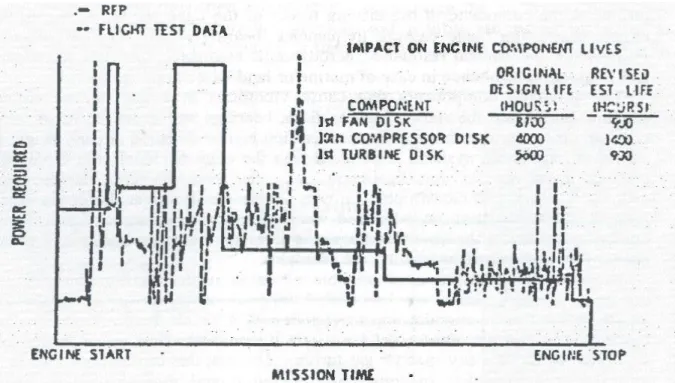
Figure 2-6: Assumed Thrust (continues line) and Real Thrust (dashed line) ...45
Figure 2-7: Overall Concept of Gas Path Analysis...49
Figure 2-8: Schematic Representation of Gas Path Analysis Procedures ...52
Figure 2-9: Non linear Gas Path Analysis Concept Representation...53
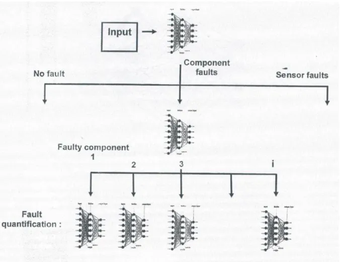
Figure 2-10: Fault Detection network...57
Figure 2-11 Fault Isolation Network...57
Figure 2-12: Fault Quantification Network...57
Figure 2-13:Artificial Neural Networks Diagnostic System...59
Figure 3-1: in flight report generation menu ... 622
Figure 3-2 on ground report generation menu ... 622
Figure 3-3: Central Maintenance System general arrangement/interfaces ... 633
Figure 3-4: Report Printer ... 677
Figure 3-5: MCDU ... 677
Figure 3-6: Previous Flight Report Print Menu ... 699
x | P a g e
Figure 3-8: CMC Possible Configuration Both Available (left) Switching (right) ... 744
Figure 3-9: Engine Monitoring Sensors Mounted Positions ... 766
Figure 3-10: EIVMU Interfaces ... 777
Figure 3-11: FADEC Outputs ... 788
Figure 3-12: FADEC Inputs ... 799
Figure 3-13: DMU Interfaces ... 822
Figure 3-14: Sample of ACMS Report ... 866
Figure 4-1: Contribution of Various Major Components to Gas Turbine Downtime (Boyce and Referex, 2002) ... 888
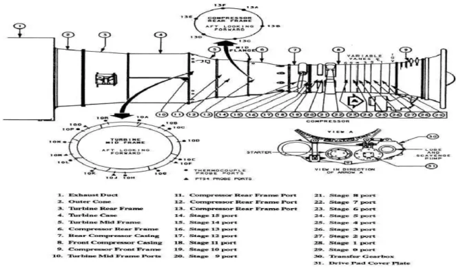
Figure 4-2: Major Failures in Gas Turbines less that 170MW (Boyce and Referex, 2002) . 888 Figure 4-3: CFM56 5B2 Cutaway Drawing ... 899
Figure 4-4: Neubauer’s classification of creep damage from observation of replicas and consequent action to be taken (Furtado and May, 2004)……….92
Figure 4-5: Creep Stages (Allison et al., 2010)………..93
Figure 4-6: Rene N5 Larson-Miller Parameter Master Curve (Walston et al.)………103
Figure 4-7: Rene N5 Larson-Miller Parameter Master Curve Plotted in Excel (Source: Author)………104
Figure 5-1: TET vs. ISA Deviation for Specific Thrust... 1122
Figure 5-2: Tb vs. ISA Deviation for Specific Thrust ... 1122
Figure 5-3: Effects of Altitude Density to Thrust (Bosdas et al., 2009) ... 1133
Figure 5-4: TET vs. Thrust Percentage for Specific ISA Condition ... 1144
Figure5-5: RPM vs. TET at 100% Thrust with Gradually Increased ISA Deviation ... 1155
Figure 5-6: RPM vs. ISA Deviation for Specific Thrust ... 1177
Figure 5-7: RPM vs. Thrust Percentage for Specific ISA Condition ... 1177
Figure 5-8: Stress vs. ISA Deviation for Specific Thrust ... 1188
Figure 5-9: RUL vs. ISA Deviation for 100% thrust ... 1255
Figure 5-10: RUL vs. ISA Deviation for 100% take-off but different duration ... 1255
Figure 5-11: RUL vs. ISA Deviation for Specific Thrust (1 min) ... 1266
Figure 5-12: RUL vs. ISA Deviation for Specific Thrust (1.5 min) ... 1277
xi | P a g e
Figure 5-14: RUL vs. Thrust Percentage for Specific ISA Condition ... 13030
Figure 5-15: RUL vs. Thrust Percentage for Constant ISA Condition (1.5 min) ... 130
Figure 5-16: RUL vs. Thrust Percentage for Constant ISA Condition (2 min) ... 1311
List of Tables
Table 3-1: Summary of Failure Classes ... 722Table 4-1: CFM56 5B2 Technical Characteristics (Lufthansa Technical Training, 1995) ... 91
Table 4-2: indicative methodology of creation of the investigated flight profiles (Source: Author) ………96
Table 4-3: Reference Thermal Model for Complete Flight ... 999
Table 4-4: Reference Stress Model for Complete Flight ... 1022
Table 4-5: Duration of the Flight Segments ... 1066
Table 4-6: Representative Result Table for Cumulative Creep ... 1088
Table 5-1: Initial Time to Failure Calculation...119
Table 5-2: Time to Failure calculation with change of -0.1 in LMP from Table 5.1...120
Table 5.3:. Time to Failure calculation with change of 10 oC from the table 5.1...120
Table 5.4: Design service life (USA DOD, 2004) ... 121
xii | P a g e
Nomenclature and Abbreviations
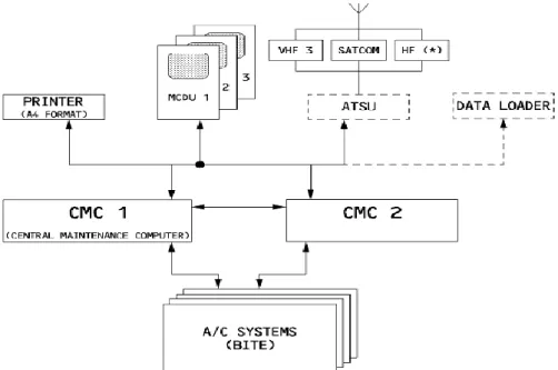
ACARS Aircraft Communication Addressing and Reporting System ACMS Aircraft Condition Monitoring System
ATSU Air Traffic Service Unit BITE Built in Test Equipment CBM Condition Based Monitoring
CBMM Condition Based Monitoring Maintenance σCF Centrifugal Forces
CMS Central Maintenance Computer CMS Central Maintenance System DAR Digital ACMS Recorder DMU Data Management Unit ECU Engine Computer Unit
EDMS Exhaust Distress Monitoring System EDMS Exhaust Distress Monitoring System
EIVMU Engine Interface and Vibration Monitoring Unit FADEC Full Authorizes Digital Engine Control
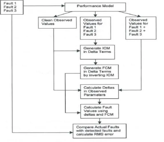
FCM Fault Coefficient Matrix h Height
ICM Influence Coefficient Matrix
IDMS Ingested Debris Monitoring System IDMS Ingested Debris Monitoring System ISC Industry Steering Committee
IVHM Integrated Vehicle Health Management
JSF PHM Joint Strike Fighter Prognostic Health Management LMP Larson-Miller Parameter
xiii | P a g e
MCDU Multipurpose Control and Display Units MDDU Multipurpose Disk Drive Unit
MEL Minimum Equipment List MSG Maintenance Steering Group MSI Maintenance Significant Items NFF No Fault Found
OSA-CBM Open Structure Architecture Condition Based Monitoring rcg Centre of Gravity radius
RUL Remaining Useful Life SAR Smart ACMS Recorder SOT Stator Outlet Temperature t time
tf time to failure Tb Blade Temperature Tcin Inlet Coolant Temperature TET Turbine Entry Temperature Tg Total Gas Temperature ε Cooling Effectiveness
εc Convection Cooling effectiveness εf Film Cooling Effectiveness ρ Density
φ% Percentage of Cooling Flow ω Angular Velocity of the Roto
1 | P a g e
Chapter
1
: Maintenance Practices
1.1
Introduction
Maintenance should be a major consideration for every company whose operations depend on machines, in order to maximize both quantity and quality of their products. Maintenance actions are defined as those that result in the restoration of a specific component to a serviceable condition or those that prevent the break-down or performance degradation of the component. For this reason the study and development of maintenance techniques is very important.
Apart from adverse weather, air traffic congestion, flight crew and passenger problems, aircraft maintenance is the main factor that impacts on an airline’s services because it keeps the aircraft on the ground. Maintenance or technical problems, affect the Dispatch Reliability (DR) of the airline, which shows the percentage of revenue departures which were not interrupted by delays or cancellations due to technical problems. DR, along with the Direct Maintenance Costs (DRCs), which are the costs incurred by the maintenance of an aircraft, are the two values that must be kept high and low respectively in order for the company to make high profits with maximum exploitation of maintenance resources (Knotts, 1999). A significant improvement in the desired levels of these two factors could be achieved by devising an accurate and specific maintenance plan. Optimum planning is essentially the optimum combination of the different maintenance techniques used. In the following chapter an analysis of those techniques will be presented. These will be divided into maintenance by level and maintenance by time, with its associated subdivisions.
maintenance Maintenance depending on level Maintenance depending on time
2 | P a g e
1.2
Maintenance According to Level
The first philosophy of maintenance depends on the depth of the associated maintenance activities and on the level of detail of the maintenance level. There are three categories, each of which refers to specific actions. The differences between these operations are due to the facilities, the tooling equipment and the personnel needed to perform each of them. Additionally, the time taken for each action to be accomplished is another restriction and is essentially the base line of every successive level. However, the separation between one level and another is blurred. Therefore, the following description is as it was found in Airbus internal publications (Airbus Industry, 2010c).
The lowest maintenance level is the Line Maintenance or on-aircraft maintenance. This is performed before the aircraft’s next flight and generally concerns actions that will not remove the aircraft from the flight schedule. The content of such a level is restricted to a quick identification and rapid replacement of faulty equipment. Such equipment are known as Line Replaceable Units (LRUs) and are designed so as to be quickly and easily removed and replaced (Kinnison, 2004). In modern aircraft this operation is continuously enhanced as maintenance enhancement systems are established that have the capability to isolate and indicate the faulty systems. A detailed description of such systems will be presented in following chapter.
According to AMC 145.A.10 (European Aviation Safety Agency, 2003), the actions that are included in line maintenance are usually those related to troubleshooting, defect rectification, removal and replacement of equipment and minor repairs or general servicing. A final check is required in order to ensure the proper functioning of the system. The checks and inspections that are performed at this level do not require special tools or in-depth analysis. In general the transit, the 24 - 48 hours, and the A - B check is performed at this stage. On every occasion the aircraft is subject to the preflight inspection at the line facilities.
The second level is the Base Maintenance. Hangar or main base maintenance is characterized by the intervention of maintenance personnel over a longer period of time, and generally concerns actions that cannot be performed at line maintenance level. For this type of maintenance, the aircraft is removed from service, and so there is a relative in convenience of time.
3 | P a g e
The major activities performed in base maintenance are the highest “C” and “D” Checks, and also any modifications on the aircraft or the aircraft’s systems by service bulletin or engineering order. For that reason, base maintenance activities require more skilled personnel combined with more sophisticated tools and facilities. Finally, the most complex are those inspections which do not rely solely on visual techniques. Non-destructive testing, which require special tools and a longer amount of time can be undertaken. However, activities that could be performed with the modification of certain details can easily be transferred to line maintenance if the operator obtains the relevant license from the manufacturer and the relevant authorities. Activities at this level are supported from the recently established maintenance enhancement systems, such as the Aircraft Condition Monitoring System, in addition to their ability to perform long time trend monitoring.
The final stage is Workshop Maintenance, which refers to both of the previous levels. Due to lack of time involved in Line Maintenance, any faulty LRUs that may have been removed are sent to the workshop in order to be made serviceable again, while equipment or components that have been removed from the aircraft during Base Maintenance are also sent to the workshops for the relevant actions. These types of equipment are easily removed and the maintenance can be carried out off-board. For example, hydraulic actuators or electrical panels can be removed and repaired off-board, unlike the structural repairs, which have to be performed on the aircraft.
These repairs need specialized workshops. Hence, every hangar has workshops which specialize in different aspects of aircraft maintenance, for example the hydraulic workshop, the avionics workshop, etc. Finally, for equipment for which there is no monitoring method or monitoring equipment installed, it is assumed that the workshop maintenance will restore them and find every ‘hidden’ failure. Such systems are those which do not have any Built in Test (BITE) function, or else the test via a control panel located in the cockpit or at the ground is not possible.
4 | P a g e
1.3
Maintenance According to Time
The division of maintenance according to time is referred to when the maintenance is going to be performed. For an airline, the level of maintenance must be linked with time, so the scheduling and the planning of these activities is essential. However, unforeseen events that require maintenance may occur, hence the schedule cannot be applied. Since safety relies on those maintenance activities they are characterized as unavoidable, and therefore, a maintenance deviation in time takes place.
Although it is sometimes inevitable, it is desirable to avoid maintenance actions that are not time-specific, known as unscheduled maintenance actions. According to Kumar et al. (1999) unscheduled maintenance actions cost a total of £1 million per wide body aircraft for every operational year. To counteract this, airlines demand from the aircraft manufacturer guarantees in order to secure Maintenance Free Operation Periods (MFOPs), during which the maintenance activities will be kept to a minimum. That period is followed by a Maintenance Recovery Period (MRP) in which all the maintenance action could take place, but with the single but very important difference that they will be scheduled (Wu et al., 2004). Apart from the unscheduled or reactive maintenance mentioned earlier, there is also the category of scheduled or proactive maintenance. However, while this category is correct, it is incomplete and has now been superseded, and the trend is now moving towards maintenance based on condition monitoring (CBMM), which constitutes a new and separate evolutionary category of maintenance known as predictive maintenance. It is difficult to categorize this type of maintenance as being either scheduled or unscheduled. However, because the main interest of this research is CBMM, the complete architecture will be described later, and in this case is assumed to be an element of preventive maintenance,as shown in Figure 2. Maintenance Proactive or Scheduled Reactive or Unscheduled Preventive maintenance Corrective maintenance Emergency maintenance
Hard time On-condition
Condition Based Monitoring
5 | P a g e
1.3.1
Reactive or Unscheduled Maintenance
The small but not insignificant category of maintenance according to time is known as reactive or unscheduled maintenance. In general terms, unscheduled procedures fall into two major categories, namely breakdown maintenance and corrective maintenance. In breakdown maintenance the operate-to-failure and the run-to-failure concepts are promoted, whereby a maintenance action is taken only when the component has failed completely and is no longer fit for purpose (Peters, 2006; Beebe, 2004).
Although this methodology has its advantages, such as taking a component’s life to its maximum, there are obstacles for its use in the aviation industry and it is subject to serious restrictions due to the fact that safety must come first. Hence, the more appropriate terms for aviation applications are corrective maintenance and emergency maintenance, depending on how urgently these maintenance actions need to be undertaken. The fact that corrective maintenance is performed with no warning, which means that it is unscheduled, makes that method similar to emergency maintenance. The majority of unscheduled activities have an emergency character and they are performed because the safety of the next flight depends on these corrections. However on many occasions unscheduled tasks are the outcome of scheduled tasks. In most cases the tasks included within corrective maintenance are the same as those of preventive maintenance, the only difference being that on the last occasion they would be pre-defined and scheduled.
The definitions that are published for that type of maintenance are numerous, but all are in agreement. Because the area of interest of this research focuses on the aviation industry, the most appropriate definition would be that which is given by the Air Transport Association, and is as follows:
“Corrective maintenance: All the actions performed as a result of failure to restore an item to a satisfactory condition by providing correction of a known or suspect malfunction and/or defect” (ATA, 1992).
The actions that are mentioned in the definition include everything which is done up until the failure is restored and the damaged system is returned to operational use. For many authors these actions begin with the identification and isolation of the defect, followed by whatever action is necessary to restore the system, namely disassembly followed by the replacement or repair of the component, and reassembly. In every case the last action should be the testing of the system.
6 | P a g e
One accurate and detailed classification of the actions performed within corrective maintenance is given in Dhillon (2006). In this approach, the process from initial identification to restoration of the item to full operation is divided into five steps, each of which includes the tasks that are appropriate for that stage. The steps are as follows:
1st Step: Failure Recognition
This is the initial step of realizing that there is a failure of a component, system or an item in general. The recognition may come from direct observation of the damaged system or - and most usually - from a cockpit indication combined with degraded performance. In this step lies the true difference between preventive and corrective maintenance, which is that the problem and the failure must exist before every corrective action is performed (Mobley et al., 2008).
2nd Step: Failure Localization
The outcome of the first step will be failure localization. Even though the recognition of a failure also indicates the location of the failure, the second step does not have that responsibility. The purpose of this step is the investigation of the component which is causing the damage, and additionally, whether the damage to one system has affected another nearby.
3rd Step: Diagnosis within the Equipment or Item
Following the previous step is the diagnosis of what the failure is and how it can be fixed. This crucial because the correct diagnosis can prevent the problems caused by a wrong diagnosis. The worst case scenario is the combination of unscheduled maintenance with a No Fault Found situation (NFF). According to research conducted for British Airways, the NFF situation cost a total of £20 million, with 8000 removals per month and an average of 14% NFF (Gatland and Trevor, 1993). Therefore, the last three steps are dedicated functions of monitoring systems on modern aircraft.
4th Step: Failed Part Replacement or Repair
Obviously this is the core of the maintenance activity and includes everything that is done in order for the system to return to service. The main activities performed are the replacement, repair, or servicing of the failed item or equipment. However, the system is not fully operable after that step. The final touch is provided by the 5th step.
7 | P a g e
5th Step: Return System to Service
In the aviation industry, great importance is attached to the final check of every piece of equipment, and that is the essence of this final step. Minor alignments and/or adjustments may be necessary, and they will only be apparent after a full check.
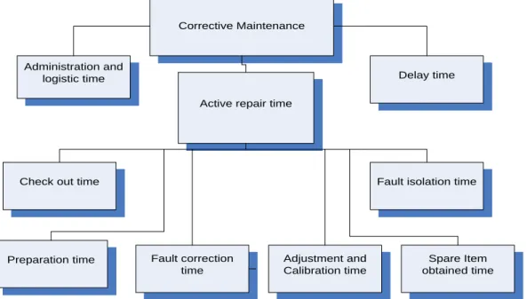
The fact that corrective maintenance is an unscheduled event makes it undesirable for the airline operators, because unscheduled downtime brings with it its own consequences. As shown in Dhillon (2006), downtime can be divided into the following categories (Figure 1.2). A similar categorization is presented in Knotts (1999).
Corrective Maintenance
Administration and logistic time
Active repair time
Delay time
Check out time
Preparation time Fault correction time
Spare Item obtained time Fault isolation time
Adjustment and Calibration time
Figure 1-3: Deviation of corrective maintenance downtime (Source: Author)
Since total elimination of these downtimes is impossible, improvement is essential. Taking this into account, and also the fact that maintenance is an unavoidable action for systems/components when they exceed a specific limit, aviation manufacturers are trying to develop methods that can offer, as much as possible, a reduction in these downtimes. Therefore, in every design philosophy that is followed each time, namely Safe Life, Fail Safe and Damage Tolerance, the concept of reliability and maintainability is integrated in order to improve the maintenance process regarding economics, safety, logistics and availability (Wikstén and Johansson, 2006).
8 | P a g e
The primary goal of maintenance downtime reduction, as studies have shown could be achieved by improving basic factors such as the initial design configuration of the aircraft, but also by making the maintenance process easier and the dispatch permission more flexible. An improvement is been underwent for every of the previous sectors. Initially, the paramount importance should and is given in the design factors that are responsible for the inherent ability of the aircraft to produce failures (Wu et al., 2004).
The first design improvement is the accessibility of the systems and the components. As has been observed from past experience, the majority of the time is taken up in accessing the failed parts. Thus, by paying attention to this at the design stage, a substantial saving can be made. Further savings can be achieved by improved fault recognition, localization, and isolation (Dhillon, 2006). This should be the second design consideration because easy access within the system is not enough on its own. It is hard for a complex system to recognize where the failure is, and thus any help provided by any means is desirable. Additionally, extra costs could be incurred when the recognition is not accurate and a NFF situation arises (Wu et al., 2004).
The improvement of these factors could result in significant improvements for both corrective and preventive maintenance, the difference being that in a scheduled maintenance action, when the operator has to take the aircraft out of service, the downtime is already determined. However as mentioned earlier, improvements could be made by making the dispatch permission more flexible.
Thus, and referring mostly to downtime reduction caused by unscheduled events, the operators, in cooperation with the authorities, have established the Minimum Equipment List (MEL). The purpose of this list is to permit an aircraft to fly safely despite the fact that some systems or pieces of equipment on it are inoperative (Kinnison, 2004; Federal Aviation Administration, 2010). The MEL is unique for every type of aircraft, however the operator can change it if he receives approval from the regulatory authorities and the manufacturer. Finally, the MEL defines the intervals at which the systems or the pieces of equipment that it lists must be rectified (Bristow and Place, 2011).
9 | P a g e
Additionally, the manufacturers have developed Line Replaceable Units (LRUs), based on the concept that the majority of systems on the aircraft are hosted in boxes that can easily be removed and replaced. Initially, this method was intended to provide maximum improvement for avionics systems, however, it is also being used in conjunction with a number of mechanical systems. The LRUs, along with maintenance enhancement systems had boost the maintenance especially the Line Maintenance procedures which in turn triggers a reduction in Turn Around Time (TAT). Consequently, the operator will reap greater benefits if the aircraft does not use the line facilities of a foreign airport any more than is necessary (Papakostas et al., 2010a).
However, it is the author’s opinion that the greatest improvement is likely to be brought about by the full integration of condition monitoring systems, which will assess virtually everything related to maintenance performance. The concept of condition monitoring will also improve deficiencies resulting from human factors, logistic organization and inaccurate maintenance planning orders which do not apply consistently to each different use that an aircraft could have. For example, maintenance planning manuals are created for certain aircraft types even though not every aircraft of the same type is likely to be flying under the same conditions. This is where the true benefits of CBMM will be reaped, and a discussion of these benefits will be presented later in this study in the form of a case study concerning the impact of the take-off performance conditions on the maintenance activities and remaining useful life of an aero engine.
10 | P a g e
1.3.2
Preventive or Scheduled Maintenance
The term ‘preventive maintenance’ was first introduced in 1957 in a handbook of engineering maintenance. In a rapidly changing world where the accurate management of peripheral maintenance actions such as logistics management was necessary, the disadvantages resulting from the deficiencies of corrective maintenance were no longer affordable. For that reason, and in order to achieve optimum resource organization, a preventive approach to maintenance was established (Stapelberg, 2009).
The fact that all maintenance actions spring from the principle of fixing something before it breaks made the preventive model of maintenance a scheduled model of maintenance. This concept was quickly adopted by the aviation industry because it completely endorsed the concept that safety must come first. This concept was termed Reliability-Centered Maintenance, and was quickly developed in order to achieve cost-effectiveness by minimizing downtimes along with the elimination of chances for failure (Kothamasu et al., 2006). Since 1957 many definitions have been given for preventive maintenance, but it is considered appropriate to reiterate the definition as provided by the Civil Aviation Authority, as follows:
“Preventive maintenance. All actions performed at defined internals to retain an item at a serviceable condition by systematic inspection, detection, replacement of worn out items, adjustment, calibration cleaning etc.” (ATA, 1992).
Even though the actions that are performed in preventive maintenance do not differ from those of corrective maintenance, the fact that they are predetermined provides a very clear picture of what is done and when. According to Dhillon (2006), in order to perform preventive maintenance we have to deal with seven elements, of which the first and most important is the periodical inspection. In this initial operation, the mechanic/inspector must check the desired system, component or item in order to determine its serviceability and whether the item still meets its initial standard. Calibration is the next stage, in which the detection and adjustment of any discrepancy in the component takes place.
In addition to inspection, testing is performed periodically in order to detect any kind of degradation. The testing procedures could be part of the inspection, as noted earlier, but they are also part of the final release. Servicing is the element that includes any periodical actions that should be undertaken in order to avoid incipient failures. These actions could be lubricating and cleaning, and are not to be confused with the installation; that is, the periodic replacement of predetermined limited-life items (European Aviation Safety Agency, 2003).
11 | P a g e
Finally, adjustment and alignment are the corrective actions which must be done after a service or installation, and include minor changes that improve the performance of the component.
The sequence in which these maintenance elements are listed by Dhillon (2006) is not what actually happens in a real aircraft maintenance performance, and such tasks are the elements of proactive maintenance. Additionally, in a real maintenance operation, some tasks could be omitted if the manufacturer makes it clear in the maintenance manual. This is understood in the context of aircraft maintenance because for almost everything on an aircraft, and more importantly, for the flight critical systems, the manufacturers have conducted extensive tests before launching into mass production. In these tests the systems are subjected to every kind of stress, i.e. mechanical, physical etc., and the results are compared with the optimum values that a system or component has at the beginning of its life.
By means of the usage diagnostics for recommended and expected operating conditions, the manufacturer provides exact and accurate procedures that must be followed by defining the time internals at which they should be done. A similar assessment will be demonstrated later in this study by calculating the remaining useful life for turbine blades. It should be noted that the following case study will concern about the design and not the post service lifing approach. Starting with the inspection and ending with the final delivery in a serviceable condition of the item, the manufactures describes the servicing, installation, alignment, adjustment, calibration and finally the testing procedures.
As established and recognised by The United Kingdom Civil Aviation Authority in 1992 and presented in Knotts (1999) and Kinnison (2004), there are two types of aircraft maintenance under the preventive umbrella. Both depend on the time at which the maintenance is undertaken and they way in which it is organized. Along with condition monitoring, which will receive the greatest interest in this research, and which will be discussed later separately, these three categories also belong to the process-oriented maintenance approach.
The first category and most common approach to aircraft maintenance is known as the hard-time process. Maintenance performed in hard-hard-time means that everything is totally predefined in terms of time as well as process. The systems and the associated components belong to categories that have a definite lifetime, and their use must not exceed a specific total limit. The measurement of exceedence could be counted in various ways such as flight hours, cycles, etc. The maintenance actions, which could be servicing and overhaul, depending on the manufacturer’s guidelines, are performed at the next scheduled maintenance. However, along with the ageing affected components, into this category fall all
12 | P a g e
flight-critical systems and components. For these systems, even though their remaining useful life may be longer, replacement is essential. However, this is the major deficiency of the process; something which is improved by the use of CBMM. Finally, items for which an accurate condition check is not possible, such as composites or plastics, are included in the hard time process.
The mid-point between hard-time and condition monitoring is the on-condition process. The factor that is predefined in this process is the time interval at which a check must be performed, both before and after the maintenance action, depending on the check results. This is because the items that come under that process do not have a definite life expiry, and only a test could establish their current condition. The tests that are performed do not take the form of a simple inspection. They are more detailed and sophisticated tests that ensure the guaranteed and without-failure operation of the system. The tested component must be fully operable until the next pre-defined on-condition test without presenting any in-flight failure. In any other condition, it must follow the prescribed actions such as overhaul and restoration. If a test for a component cannot provide enough information about its condition without performing a tear-down inspection, the component must not be assigned for on-condition maintenance. The components that usually come under this process are the tyres, the brakes and the engine, by performing oil analysis and borescope inspections. As mentioned earlier, the intervals at which a hard-time or an on-condition maintenance process is undertaken are predetermined and are counted in many ways. For almost every reason, the first time should be when the aircraft is in operation, meaning when the engines are running, known as flight hours. Another option is by measuring flight cycles. One flight cycle begins when the last wheel leaves the ground and ends when the last wheel touches the ground again. However, these time-based intervals are useful for systems that are in operation during the entire duration of the flight or only during takeoff and landing, such as the engines and the hydraulic system, or the tyres and brakes.
Modern aviation uses checks that are a combination of these timed intervals, but also the level of maintenance that will be undertaken. Starting with the Transit Check, the aircraft is subjected to inspection before take-off and after landing. This is the minimum kind of check and the actions that can be taken are limited to line maintenance. The 24 and 48-hour checks follow the same principles. The level of maintenance is again restricted to line maintenance, but the level of the inspection is more detailed. Finally, the most common approach is the check defined by letters. Letter checks tend to eliminate all the other ways of counting and performing maintenance because they combine the hourly counting with the level of maintenance.
13 | P a g e
Starting with the lighter A Check performed on a regular basis, the aircraft receives low level maintenance. The tasks involved in this kind of check are essentially those of the transit and 24-hour check, and are restricted to visual inspections, servicing procedures and small equipment tests. A more extensive and detailed form of the A Check is the B Check, with its tasks remaining at a low level. This kind of check is usually omitted by airlines and its associated maintenance activities are split between the A Check and the next category which is the C Check. This is a major check and requires special tools, premises and human resources. Specific components are removed from the aircraft for inspection and testing with additional detailed structural inspections. The heaviest version of a C Check is the D Check, which requires the same functions as a C Check, but can keep the aircraft out of service for up to one month (Hessburg, 2000). The time at which a C or a D Check must be performed is determined by the manufacturer, or is planned by the airline after the proposed maintenance planning has been approved by the relative aviation authority. The criteria are not the same for every operator because of the differences which result from the operational environment of the airline, e.g. constant flights over deserts, or the aircraft’s operational use, e.g. VIP aircraft do not operate in the same way as a commercial airline fleet.
Every higher check includes every lower check. An airline devises the maintenance planning depending on its needs, thus it adds every maintenance action that must be done in the most appropriate check in terms of time and only. For example, if an A check is close to a C Check, it is possible for actions that have a time window to be performed in the C Check, and to skip the A Check.
14 | P a g e
1.3.3 Maintenance Steering Group (
MSG)
3
In order to create an effective preventive maintenance program it is essential to have available in our hand every kind of availability ranging from data till personnel. This could mean availability of logistics, tools, test instruments, personnel, maintenance manuals and also historical data. However there is a general approach that is covered in six steps, and by following these, an optimum maintenance program can be created (Dhillon, 2006) . The steps are as follows:
1st step is the identification and selection of the area that needs extra attention.
2nd step is to define the need in terms of preventive maintenance and establish periodic inspection and tasks.
3rd step is to determine the frequency of these assignments depending on the manufacturer’s orders and the personal experience of the mechanic/engineer.
4th step is the preparation of preventive maintenance assignments daily or periodically in an effective manner, and then to get them approved.
5th step is to schedule the maintenance activities for a 12-month period.
6th step is to expand the preventive maintenance program to other areas on the basis of experience gained from the pilot preventive maintenance projects.
In the context of the aviation industry, these steps could not be applied together efficiently, because in aviation a maintenance programme must be established before the aircraft is launched onto the market. The procedure for creating a maintenance program has been developed over a period of many years before arriving at its present form and terminology. Within the aviation industry, the approach for establishing the maintenance program is determined by the Maintenance Steering Group, with the latest version being version 3 (MSG-3) (Air Transport Association of America, 1970).
This name is derived from the representatives that an MSG program needs in order to be created. These representatives cover the three aspects of aviation; the Regulatory Authority, the Industry Steering Committee (ISC) and finally the Working Groups, each of which has different responsibilities and compositions. These representatives participate as and when required because this is a process which evolves over time, starting from when a new aircraft is ready to go to the market and ending when that aircraft is no longer in operational use (Adams, 2009).
15 | P a g e
Initially, the ISC consists of the companies who manufacture the aircraft and the airlines that operate it. Even if there is only a single operator, there could be many different manufacturers because different parts of the aircraft come from different manufacturers. The initial maintenance program is created by the members of the group, with the cooperation of Working Groups, and the final decision is approved by the Regulatory Authority. Every final maintenance program is unique for every type of aircraft. If after the establishment of the initial program, a particular operator wants to change it in order to better apply it to their specific program and needs, they can, but once again it must be evaluated and confirmed by the ISC and the Regulatory Authority.
As was mentioned earlier, safety is the first priority in aviation. Thus, the MSG -3 process is a top-down process that organizes the maintenance depending on how a failure on a system or a subsystem might affect the overall safety. This process is accomplished via tree logics with possible answer “YES” or “NO” and their following consequences. The process begins with the manufacturer identifying the Maintenance Significant Items (MSI), which can be either systems or components. The process of identifying them fulfilled in six very important steps:
I. The manufacturer begins to partition the aircraft’s major functional areas as they are defined in the ATA chapters until all the on-aircraft replaceable components have been defined.
II. The manufacturers have to use the top-down approach in order to list the MSI.
III. The following questions must be applied to the MSI:
a. “Could failure be undetectable or not likely to be detected by the operating crew during normal duties?”
b. “Could failure affect safety (on the ground or in flight), including safety/emergency systems or equipment?”
c. “Could failure have a significant operational impact?” d. “Could failure have a significant economic impact?”
IV. For any items for which even one question is answered “YES”, the analysis begins, and for those for which all questions are “NO”, no further analysis is required.
V. The possible MSI list is ready and the ISC reviews and approves it, then gives it to the working groups.
16 | P a g e
After the selection of the MSIs, the next thing that must be done is the identification of the 1) function, 2) functional failures, 3) failure effects, 4) failure causes. The analysis is then ready to begin, divided into two levels, and again using the same question answering method. The first level of analysis concerns the consequences of failure. The questions that have to be answered are:
“Is the occurrence of a functional failure evident to the operating crew during the
performance of normal duties?”
“Does the functional failure or secondary damage resulting from the functional failure have a direct adverse effect on operating safety?”
“Does the combination of a hidden functional failure and one additional failure of a system related or back-up function have an adverse effect on operating safety?”
“Does the functional failure have a direct adverse effect on operating capability?”
The second level is the task development level, for which six questions must be answered.
“Is a lubrication or servicing task applicable and effective?”
“Is a check to verify operation applicable and effective?”
“Is an inspection or functional check to detect degradation of function applicable and effective?”
“Is a restoration task to reduce failure rate applicable and effective?”
“Is a discard task to avoid failures or to reduce the failure rate applicable and effective?”
“Is there a task or combination of tasks applicable and effective?”
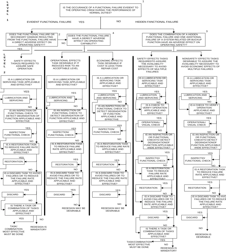
The evaluation of the above gives the decision tree diagram (Figure 1.4) and creates the Maintenance Report Board (MRB). In addition to the MRB, but always based upon it, the manufacturer publishes their own Maintenance Planning Document (MPD). This is a generic term, and each manufacturer can use their own preferred name; for example, Airbus calls it the Maintenance Planning Document, while Boeing uses the term Maintenance Planning Data.
An MSG-3 maintenance program provides maximum aircraft availability as a result of equipment availability and reduction of extended inspection intervals. It also ensures the aircraft’s inherent safety and reliability along with the operational safety, suitability and effectiveness. In addition, it is a cost avoidance method. To summarize, it integrates all levels of maintenance activity while ensuring that all equipment is thoroughly covered by the proper level of inspection (Voith Industrial Services, 2010). Thus, it ensures that the majority of aviation demands are covered. These demands can be simply and accurately
17 | P a g e
summarized in two points; safety must come first, and then after there is no point in maintenance if failure is cheaper (Bristow and Place, 2011; Mann et al., 1995).
IS THE OCCURANCE OF A FUNCTIONAL FAILURE EVIDENT TO THE OPERATING CREW DURING THE PERFORMANCE OF
NORMAL DUTIES?
EVIDENT FUNCTIONAL FAILURE YES NO HIDDEN FANCTIONAL FAILURE
DOES THE FUNCTIONAL FAILURE OR SECONDARY DAMAGE RESULTING FROM THE FUNCTIONAL FAILURE HAVE
A DIRECT ADVERSE EFFECT ON OPERATING SAFETY?
DOES THE FUNCTIONAL FAILURE HAVE A DERECT ADVERSE
EFFECT ON OPERATING CAPABILITY?
DOES THE COMBINATION OF A HIDDEN FUNCTIONAL FAILURE AND ONE ADDITIONAL FAILURE OF A SYSTEM RELATED OR BUCKUP FUNCTION HAVE AN ADVERSE EFFECT ON
OPERATING SAFETY?
IS A LUBRICATION OR SERVICING TASK APPLICABLE
AND EFFECTIVE? LUBRICATION AND SERVICING IS AN INSPECTION OR FUNCTIONAL CHECK TO DETECT DEGRADATION OF FUNCTION APPLICABLE AND
EFFECTIVE
INSPECTION/ FUNCTIONAL CHECK
IS A RESTORATION TASK TO REDUCE FAILURE RATE
APPLICABLE AND EFFECTIVE? RESTORATION
IS A DISCARD TASK TO AVOID FAILURES OR TO REDUCE
THE FAILURE RATE APPLICABLE AND EFFECTIVE? DISCARD IS THERE A TASK OR COMBINATION OF TASKS APPLICABLE AND EFFECTIVE? IS A LUBRICATION OR SERVICING TASK APPLICABLE
AND EFFECTIVE? IS A LUBRICATION OR SERVICING TASK APPLICABLE AND EFFECTIVE? IS A LUBRICATION OR SERVICING TASK APPLICABLE AND EFFECTIVE? IS A LUBRICATION OR SERVICING TASK APPLICABLE AND EFFECTIVE? LUBRICATION AND SERVICING IS AN INSPECTION OR FUNCTIONAL CHECK TO DETECT DEGRADATION OF FUNCTION APPLICABLE AND
EFFECTIVE?
INSPECTION/ FUNCTIONAL CHECK
IS A RESTORATION TASK TO REDUCE FAILURE RATE APPLICABLE AND
EFFECTIVE?
RESTORATION IS A DISCARD TASK TO AVOID FAILURES OR TO REDUCE THE FAILURE RATE
APPLICABLE AND EFFECTIVE? DISCARD IS AN INSPECTION OR FUNCTIONAL CHECK TO DETECT DEGRADATION OF FUNCTION APPLICABLE AND EFFECTIVE LUBRICATION AND SERVICING LUBRICATION AND SERVICING LUBRICATION AND SERVICING IS A CHECK TO VERIFY OPERATION APPLICABLE AND EFFECTIVE? IS A CHECK TO VERIFY OPERATION APPLICABLE AND EFFECTIVE? INSPECTION/ FUNCTIONAL CHECK IS A RESTORATION TASK TO REDUCE FAILURE RATE
APPLICABLE AND EFFECTIVE?
RESTORATION IS A DISCARD TASK TO AVOID FAILURES OR TO REDUCE THE FAILURE RATE
APPLICABLE AND EFFECTIVE? DISCARD OPERATIONAL/ VISUAL CHECK OPERATIONAL/ VISUAL CHECK IS AN INSPACTION OR OR FUNCTIONAL CHECKTO DETECT DEGRADATIONOF FUNCTION APPLICABLE ANDE EFFECTIVE? IS AN INSPACTION OR OR FUNCTIONAL CHECKTO DETECT DEGRADATIONOF FUNCTION APPLICABLE ANDE EFFECTIVE? INSPECTIO/ FUNCTIONAL CHECK INSPECTIO/ FUNCTIONAL CHECK IS A RESTORATION TASK TO REDUCE FAILURE RATE APPLICABLE AND EFFECTIVE? IS A RESTORATION TASK TO REDUCE FAILURE RATE APPLICABLE AND
EFFECTIVE?
RESTORATION RESTORATION
IS A DISCARD TASK TO AVOID FAILURES OR TO REDUCE THE FAILURE RATE APPLICABLE AND
EFFECTIVE?
IS A DISCARD TASK TO AVOID FAILURES OR TO REDUCE
THE FAILURE RATE APPLICABLE AND EFFECTIVE? DISCARD DISCARD IS THERE A TASK OR COMBINATION OF TASKS APPLICABLE AND EFFECTIVE? 1 2 3 4 NO YES OPERATIONAL EFFECTS TASK DESIRABLE IF IT REDUCES RISK TO AN ACCEPTABLE LEVEL REDESIGN MAY BE DESIRABLE SAFETY EFFECTS TASK(S) REQUIRED TO ASSURE SAFE OPERATION TASK/ COMBINATION MOST EFFECTIVE MUST BE DONE REDESIGN IS MANDATORY ECONOMIC EFFECTS TASK DESIRABLE IF COST IS LESS THAN
REPAIR COST
SAFETY EFFECTS TASKS REQUIREDTO ASSURE
THE AVAILABILITY NECESSARY TO AVOID EFFECTS OF MULTIPLE
FAILURES
NONSAFETY EFFECTS TASKS DESIRABLE TO ASSURE THE AVAILABILITY NECESSARY TO AVOID ECONOMIC EFFECTS OF
MULTIPLE FAILURES YES NO YES NO YES NO YES NO YES NO YES NO YES NO YES NO YES NO YES NO YES NO YES NO REDESIGN MAY BE DESIRABLE YES NO YES NO YES NO YES NO YES NO YES NO TASK/COMBINATION MOST EFFECTIVE
MUST BE DONE REDESIGN IS MANDATORY YES NO YES NO YES NO YES YES NO NO REDESIGN IS DESIRABLE YES NO L E V E L 1 L E V E L 2
18 | P a g e
1.4
Condition Based Monitoring
Condition Based Monitoring (CBM) is a state-of-the-art technique in performing maintenance which is the called Condition Based Monitoring Maintenance (CBMM). It combines reactive and preventive maintenance, the outcome of which is the predictive way that maintains the values of aviation reliability-centered maintenance (Figure 1.5). Briefly, by using this method, the operator can monitor the state of the component and then schedule the maintenance which is needed at the time, while also exploiting the whole remaining useful life of the component. This method was first developed by Boeing in order to create a new method of preventative maintenance for the new - in those days - 747 model (Bengtsson, 2004), which would respect the reliability-centered concept of the existing MSG, but would be more efficient (Tsang, 1995). The actual research did not refer to CBM from the beginning, but to the tendency of the aircraft components to failure.
That research was commissioned by the US Department of Defense and revealed that approximately 11% of the components had characteristics that deteriorated as a result of ageing. Regarding these components, the scheduled hard-time maintenance process was a solution which could be defined and predetermined in terms of time or other criteria such as flight cycles. For the remaining 89% which did not show ageing characteristics and whose maintenance could not be ‘predicted’, the need to develop a new method for maintenance was obvious (Nolan and Heap, 1978). That new method turned out to be condition-based monitoring, which provides the opportunity for on-demand maintenance.
Maintenance evolving through time Reactive maintenance Preventive maintenance Corrective maintenance Preventive maintenance Hard time maintenance On-condition maintenance Reliability-centered maintenance Predictive maintenance Condition based monitoring
19 | P a g e
In its early stages, this method did not have a clear character, and belonged to both of the major categories of preventative maintenance, namely scheduled and unscheduled. More accurately, due to the lack of monitoring techniques, condition monitoring was restricted to components that did not have a definite lifetime, and as such, their replacement was on demand. The monitoring technique was restricted to the experience and the physical senses of the mechanic, in combination with crew reports referring to system malfunctions.
Most importantly, the components that fall under condition monitoring should follow the specifications that have been defined by the aviation authorities (Air Transport Association of America, 1970; Civil Aviation Authority, 1997). Specifically, the Condition Monitored (CM) item must not be a vital component on which the airworthiness, reliability or safety of the flight depends. Moreover, no ‘hidden functions’, i.e. affecting side components or systems are acceptable if a failure on the monitored component occurs. In addition, the operator has to include the CM items into a data collection and analysis program in order to better understand the reasons for failure, for future use. However, condition monitoring maintenance tends now to be a fully predictive maintenance, something that is achieved by using very sophisticated monitoring, diagnostic/prognostic methods in all of the systems, regardless of their criticality. This is also the difference between on-condition and condition monitoring maintenance.
In recent times, companies are facing a dramatic change because of the need for high productivity in order to be competitive and leading-edge. The key for high productivity is to achieve high levels of availability (Butcher, 2000; Olsson et al., 2004). For an airline this would translate into the maximum availability of their fleet in order to have a maximum operational profile, which means maximum productivity (Papakostas et al., 2010b).
By performing predictive maintenance by using the capabilities of CBM, the operators can benefit from the fact that every component that is been replaced has reached the end of its life. They can avoid unscheduled maintenance actions, and can create an accurate preventive maintenance plan that precisely suits the aircraft’s use. Additionally, the situation of keeping the aircraft on the ground for long periods of time because of a failure in a component that is too big and too expensive to be kept as a spare can be eliminated (Provan, 2003), because the logistics management is improved by predicting the incipient failure.The benefits of utilizing CBM were first observed in the army, which began research in order to implement CBM techniques in existing helicopters and aircraft (Hess, 2002). Currently, a very sophisticated outcome of that research is in use with the state-of-the-art CBM on the JSF F-35.
20 | P a g e
1.5
Condition Based Monitoring Architecture
In order for a tool such as condition monitoring to be fully operable and for its integration to be achievable, the existence of an architecture capable of hosting its functions is essential. The need for a standard CBM architecture was soon recognized, and a fundamental framework was established (Discenzo et al.). This framework consisted of functional system elements, interface requirements, and also the operational procedures that a CBM architecture, and subsequently a specific CBM system, must implement. This initiative was undertaken by representatives from industries and universities to army representatives, covering everything that is involved in a CBM system (Lebold et al., 2003).
Essentially, what was actually needed from a CBM method was a reduction of the costs of maintenance combined with maximum safety. The safety aspect had already been fully accomplished with the previous techniques, but the losses incurred by the unnecessary replacement of equipment was no more affordable. Consequently the most important requirement of a CBM system is to be able to diagnose the current condition and predict incipient failures for the component under inspection. By definition, that process will show the remaining useful life of the component.
In order to accomplish this central requirement of diagnosing/predicting, the systems have to have separate dedicated functions such as data acquisition and processing, and so the outcome and the combination of these should provide the desired data. More specifically, the key utilities and activities that a complete CBM system should have begin with the data sensing and acquisition, followed by the initial processing of these, along with feature extraction. The result of the data processing is the triggering of the alert mechanism, firstly with the diagnosis, and then with prognostic enhancement.
Additional decision support is desirable, along with possible recommendations in general, and is almost essential for a system to be as near perfect as possible. The partition of every task into separate functions should to be a separate piece of the system, or even better, a separate layer. By setting these requirements as goals for the system, the desired operational requirements and system elements respectively have been covered (Discenzo et al.).
21 | P a g e
The aforementioned CBM architecture was standardized to Open Structure Architecture-Condition Based Monitoring (OSA-CBM) in 2001. The program began from zero because no framework existed and was led both from industry and the Army through a Dual Use Science and Technology (DUST) program. The participants covered a range of industrial, commercial, and military applications of CBM technology: Boeing, Caterpillar, Rockwell Automation, Rockwell Science Center, Newport News Shipbuilding, and Oceana Sensor Technologies. Other team contributors included the Penn State University / Applied Research Laboratory and MIMOSA (Machinery Information Management Open Standards Alliance) (Thurston, 2001).
During that time several versions of an OSA CBM architecture were introduced, with the latest version, V.3.3.0, taking the following form (Penn State University et al., 2006). Extensive details of all of them are publicly available on the MIMOSA website www.mimosa.org. The things that have been changed from the first version do not apply to the actual layers but to the interaction between them. Furthermore, the human interface, which is considered to be the top layer, does not appear in the latest edition, but that does not mean that it isn’t present.
The sequence in which the layers appear refers to the representation of the data flow and to the way in which the elements should be follow one another. It should be noted that the architecture described below was found in many publications. However it seems better to analyze the latest adding some details found in other publications. Beginning with data acquisition and ending with the human display, the seven layers are as follows:
1st lLayer: Data Acquisition or Sensor Module
The first layer is responsible for feeding the CBM system with the correct data that the system needs in order to proceed with the processing and provide results. The sources of these data are sensors that monitor the desired component. Fraden (2003) defines a sensor as a “device that receives and responds to a signal or stimulus”. After acquisition these data must always be digitized, but a Word output is also acceptable. The establishment of Micro Electromechanical Systems in the CBM market has reduced the size and the price, and has brought along with it advantages such as temperature stability, self-test functions, low drift and sensor redundancy (Bengtsson, 2004). In the event that the sensor is unable to produce digital outputs from the beginning, a transducer is fitted to complete the task. Essentially, this is a conversion from analog to digital, achieved by adding electrical or optical energy to the signals. In addition, the sensor layer should be able to calibrate the data obtained and must also be able to provide secondary information to its interfaces, such as sampling rate and