A Three-dimensional Forward
Dynamic Model of the Golf Swing
by
Daniel Johnson
A thesis
presented to the University of Waterloo in fulfillment of the
thesis requirement for the degree of Master of Applied Science
in
Systems Design Engineering
Waterloo, Ontario, Canada, 2015
I hereby declare that I am the sole author of this thesis. This is a true copy of the thesis, including any required final revisions, as accepted by my examiners.
Abstract
A three-dimensional (3D) predictive golfer model can be a valuable tool for investigating the golf swing and designing new clubs. A forward dynamic model for simulating golfer drives is presented, which includes: (1) a four degree of freedom golfer model, (2) a flexible shaft model based on Rayleigh beam theory, (3) an impulse-momentum impact model, (4) and a spin rate controlled ball trajectory model. The input torques for the golfer model are provided by parameterized joint torque generators that have been designed to mimic muscular inputs. These joint torques are optimized to produce the longest ball carry distance for a given set of golf club design parameters. The flexible shaft model allows for continuous bending in the transverse directions, axial twisting of the club and variable shaft stiffness along its length. The completed four-part model is used for examining the following parameters of interest in club design by performing simulation experiments: clubhead mass, clubhead centre of mass location, clubhead moment of inertia, shaft flexibility, and clubhead and shaft aerodynamics.
Analysis of the experiments led to the following recommendations for golf club design:
1. The clubhead mass should continue to be around 200g.
2. The centre of mass of the clubhead should be as close to the face as possible.
3. Shaft flexibility should be tuned for an individual golfer, depending on their particular swing.
4. Clubhead and shaft aerodynamic drag have a significant effect on the ball carry and clubhead orientation, and should be minimized during the club design process.
Acknowledgments
I would like to thank all the people who helped make this thesis possible. In particular I’d like to thank my supervisor, Professor John McPhee for his support, ideas, and sug-gestions throughout the process of creating this work. I’d also like to thank Dr. Joydeep Banerjee for his help with modeling clubhead and shaft aerodynamics, Dr. Steve Quin-tavalla for support in modeling ball aerodynamics, and Dan Wilson for help debugging the impact model and providing me with insight into how golfers think about their swings.
I’d also like to acknowledge Professor David Clausi and Dr. Chad Schmitke for reading this thesis and providing invaluable suggestions for improving this work.
I would like to acknowledge the Natural Sciences and Engineering Research Council of Canada and the Government of Ontario for providing funding support during the comple-tion of this thesis.
Table of Contents
List of Figures ix
List of Tables xiii
1 Introduction 1
1.1 Motivation and Goals . . . 2
1.2 Project Outline . . . 2
1.3 Contributions . . . 3
1.4 Document Structure . . . 4
2 Background and Literature Review 5 2.1 Golf Swing . . . 6
2.1.1 Biomechanics of the Golfer . . . 6
2.1.2 Muscle Dynamics and Passive Joint Torques . . . 8
2.1.3 Club Flexibility . . . 14
2.1.5 Ball Aerodynamics . . . 23
2.2 Golf Driver Design . . . 26
2.2.1 Club Mass . . . 26
2.2.2 Clubhead Moment of Inertia . . . 27
2.2.3 Clubhead Centre of Mass Position . . . 27
2.2.4 Shaft Flexibility . . . 28
2.3 Golfer Models . . . 29
2.3.1 Early Golfer Models . . . 29
2.3.2 Modern Golfer Models . . . 30
2.3.3 Other Golfer Models of Interest . . . 33
2.4 Opportunities . . . 34
3 Golfer Model 36 3.1 Biomechanical Golfer Model . . . 36
3.1.1 Active Muscle Torques . . . 39
3.1.2 Passive Muscle Torques . . . 43
3.1.3 Control of the Swing . . . 46
3.1.4 Validation . . . 46
3.2 Flexible Club Model . . . 47
3.2.1 Flexible Shaft . . . 47
3.2.3 Clubhead and Shaft Aerodynamics . . . 52
3.2.4 Validation . . . 57
3.3 Combined Club and Golfer Model . . . 58
3.4 Impact Model . . . 58
3.4.1 Validation . . . 67
3.5 Ball Aerodynamics . . . 68
3.5.1 Validation . . . 71
3.6 Optimal Control . . . 71
3.6.1 Objective Function One: Maximum Clubhead Velocity . . . 72
3.6.2 Objective Function Two: Ball Carry . . . 74
3.7 Complete Model . . . 76
3.8 Implementation . . . 76
4 Results and Discussion 80 4.1 Results for the Default Parameters . . . 81
4.2 Effect of Golfer Strength . . . 90
4.3 Effect of Clubhead Mass . . . 94
4.4 Effect of Clubhead Centre of Mass Position . . . 97
4.5 Effect of Clubhead Moment of Inertia . . . 103
4.6 Effect of Shaft Flexibility . . . 104
4.8 Model Limitations . . . 110
4.8.1 Limitations of the Golfer Model . . . 111
4.8.2 Limitations of the Club Model . . . 114
4.8.3 Limitations of the Impact Model . . . 115
4.8.4 Limitations of the Ball Aerodynamic Model . . . 115
5 Conclusions and Future Work 117 5.1 Project Summary . . . 117
5.2 Recommendations . . . 119
5.3 Future Research . . . 119
References 123
APPENDICES 130
List of Figures
2.1 An illustration of muscle activation and deactivation dynamics [1]. . . 8
2.2 Force-length curve for active portion of a human muscle [1]. . . 10
2.3 Full force-length curve for a muscle including passive and active components. 11 2.4 Normalized force-velocity curve for a typical muscle [1]. . . 11
2.5 General shape of the passive joint moment [2]. . . 13
2.6 Illustraction of clubhead droop. . . 15
2.7 Typical flexing pattern of the club during the swing. . . 16
2.8 Top view of an open clubface orientation (left) and a closed clubface orien-tation (right). . . 19
2.9 Illustrating the “gear effect” for a toed shot. . . 21
2.10 Top view of the effect of side spin on the flight of the golf ball. . . 24
2.11 Flight paths of the ball illustrating the effect of backspin on the flight of the golf shot. . . 25
3.2 A comparison of muscle torques generated by Equation 3.1 to a typical muscle activation curve. . . 41
3.3 Sample joint torque curve incorporating velocity scaling . . . 42
3.4 Contour plot illustrating the passive torques for the shoulder joint [3]. . . . 44
3.5 Fitting curves for the passive forces at each joint in the golfer model. . . . 45
3.6 Flexible beam model as proposed by Shi et al. [4]. . . 48
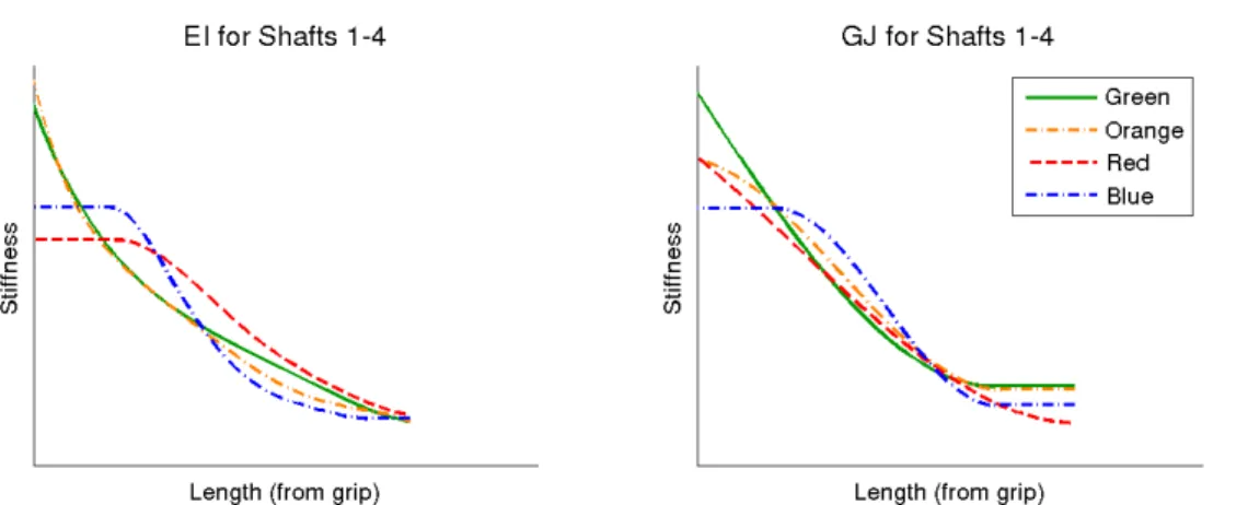
3.7 Flexible club properties provided by a club manufacturer. . . 50
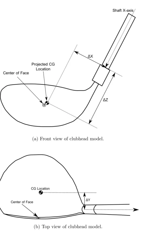
3.8 Diagram illustrating the frames of reference and measurements for the rigid body clubhead. . . 51
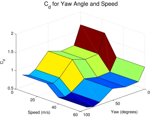
3.9 Cdvalues for the clubhead as modeled for different combinations of clubhead
speed and yaw angle. . . 53
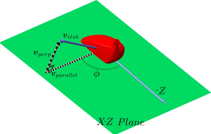
3.10 An illustration of the relevant frames and velocities for calculating the aero-dynamic loads on the clubhead. . . 54
3.11 The combined golfer and club model in the early part of a swing. The wrist has yet to break. . . 59
3.12 Side view of the impact model illustrating impulses, frames of reference, and the clubhead ellipsoid. . . 63
3.13 Top view of impact mode illustrating impulses, frames of reference, and the clubhead ellipsoid. . . 64
3.14 Free body diagram of the ball in flight. . . 69
3.15 Illustrating the required angles for calculating the penalties in objective function 3.37. . . 73
3.16 A plot of objective function 3.38 for constantX = 200 with Zmax = 10. . . 75
3.17 The complete golfer-club, impact, and carry model. . . 77
4.1 Ball trajectory for swing with default parameters. . . 82
4.2 Clubhead centre of mass speed for swing with default parameters. . . 82
4.3 Clubhead kinematics for swing with default parameters. . . 84
4.4 Golfer joint angles for swing with default parameters. . . 85
4.5 Golfer joint torques for swing with default parameters. . . 86
4.6 Total golfer joint torques for swing with default parameters. . . 87
4.7 Clubhead aerodynamics plots for swing with default parameters. . . 88
4.8 Club flexing as measured from the grip. . . 89
4.9 Ball carry plotted against golfer strength factor. . . 91
4.10 Clubhead speed plotted against golfer strength factor. . . 92
4.11 Active joint torque comparison across golfers of different strength. . . 93
4.12 Clubhead speed plotted against clubhead mass. . . 94
4.13 Ball carry plotted against clubhead mass. . . 95
4.14 Comparison between golfer swinging the default club and swinging a club with increased clubhead mass. . . 96
4.15 Ball carry plotted against clubhead mass on the range of 170 g to 200 g. . . 97
4.16 Ball carry plotted against clubhead centre of mass y-coordinate. . . 98
4.18 Joint angle comparison across swings with different clubhead centre of mass
positions. . . 100
4.19 Launch backspin plotted against clubhead centre of mass y-coordinate. . . 101
4.20 Comparison of ball trajectories for different centre of mass positions. . . 101
4.21 Forward/backward flexing of the shaft for clubs with different center of mass positions. . . 102
4.22 Comparison of ball trajectories for different clubhead MOI. . . 103
4.23 EI and GJ curves for flexible shafts used in the study. . . 105
4.24 Ball carry for different flexible shafts. . . 106
4.25 Clubhead speed for different flexible shafts. . . 107
4.26 Backspin of the ball for different flexible shafts. . . 109
4.27 Comparison of the ball trajectories with and without club aerodynamic drag.110 A.1 Green club polynomial fitting comparison. . . 132
A.2 Yellow club polynomial fitting comparison. . . 133
A.3 Orange club polynomial fitting comparison . . . 134
List of Tables
3.1 Segment mass properties of the golfer. . . 39
3.2 Segment geometry properties of the golfer. . . 39
3.3 Parameters for the four active joint torque generators. . . 43
3.4 Parameters for passive joint torques at the torso, shoulder, and wrist joints 46 3.5 Clubhead geometry and mass properties . . . 50
3.6 Measured Values of Cd for the clubhead . . . 55
3.7 Required clubhead parameters for the impact model. . . 67
3.8 Required ball parameters for the impact model. . . 68
Chapter 1
Introduction
Golf is a sport played by an estimated 80 million people worldwide on nearly 40000 courses [5]. Players and manufacturers spend billions of dollars on events, golf tourism, and equip-ment to play the game. To capture this market, golf equipequip-ment companies are constantly designing new clubs for players to use, promising gains in driving distance and accuracy, improved spin control, or other benefits to players who buy the latest technology. While it is clear that golf club technology has improved over the last 30 years [6], there is still a significant lack of understanding of the mechanisms behind this improvement. Golfers are left searching for answers within a haze of marketing information without clear scientific basis.
This thesis seeks to build our scientific understanding of the golf swing through modeling and simulation of golfers and their equipment. Along with improving our understanding of the golf swing, simulations can be used to help design and evaluate new golf clubs quickly and inexpensively.
1.1
Motivation and Goals
Computer simulations are used extensively in the design of multibody dynamic systems. In the past they have mostly been used for designing the mechanical and electrical components of systems, but improved techniques have allowed researchers to begin simulating humans interacting larger systems in biomechatronic models [7]. Simulations of the golf swing have been used since the 1970s to attempt to discover how to golf more effectively. By modeling the golf swing, we can gain insights into how golfers should swing and the best ways to design their equipment.
The goal of this project is to develop a biologically-motivated golf swing model including the golfer and club that can be evaluated based on its performance in striking the ball. The model should include variable parameters for golfer to allow for optimization of the swing and variable parameters for the golf club to test and evaluate different designs.
1.2
Project Outline
The project began with a review of existing golfer models that have been used to simulate the golf swing. The review focused on establishing what parts of the swing have been modeled and what opportunities exist for developing new golfer models. In addition, a review of manufacturer’s claims for the capabilities of new golf clubs was performed to determine what questions the model could be used to answer. This review led to the conclusion that there was a need for a biologically-motivated golf swing model that could be used for evaluating golf clubs and the marketing claims made about them. This model should be able to swing clubs in an optimal fashion and capture the biomechanics relevant to the golf swing.
To easily evaluate golf clubs within the context of the model a four-step golfer model was proposed including the golfer, club, impact with the ball, and aerodynamics of the ball’s flight. Different models were considered for each step, and the resulting selections combined together into a single simulation. This simulation of a golfer striking the ball is then optimized by changing the timing of the muscular torques that drive the model.
The final model was then used to perform several experiments on the claims made by manufacturers about new club designs. Club mass, club head moment of inertia, club head centre of mass position, and club flexibility are all examined within the context of the model. The effect of golfer strength was also investigated. Finally, the limitations of the model are addressed and some recommendations made for how to improve and expand its capabilities are made.
1.3
Contributions
Overall contribution: A biological golfer model that can be evaluated using ball trajectories.
Inclusion of a continuous flexible golf club model based on Rayleigh beam theory in a forward dynamic golfer and swing model.
Method for providing joint torques that mimic those provided by muscles, including both passive and active biological contributions.
A combined impact and aerodynamics model for predicting ball flight.
An optimization technique for determining the best swing based on ball carry for a particular golfer and club combination.
A clubhead aerodynamic model that can be used in forward dynamic simulation. A shaft aerodynamic model that can be used in conjunction with the flexible beam.
1.4
Document Structure
This document describes the process through which the four-part golfer model is created. Chapter 1 describes the goals and motivations for the project and the major contributions of this work. Chapter 2 has two goals: first, in Sections 2.1 and 2.2 to describe the basic biomechanics and physics which affect the golf swing and club design, and second in Section 2.3 to perform a literature review of the existing golfer models.
Chapter 3 describes the four-part golfer model created for this work. It is divided into four sections: Section 3.1 describes the golfer portion of the model including active and passive joint torques; Section 3.2 details the flexible club used, including aerodynamics on the clubhead and shaft; Section 3.4 describes the impulse-momentum based impact model; and Section 3.5 discusses the ball aerodynamic model.
In Chapter 4 the combined model is used to investigate the effect of golf club design decisions on the performance of golf clubs. Evaluations of the effect of a variety of golfer and club parameters on the success of the golf swing are performed and the results investigated. Limitations of the model are also addressed in this chapter.
Finally, in Chapter 5 the project is summarized and recommendations for future work are made.
Chapter 2
Background and Literature Review
In 1968, Search for the Perfect Swing by Cochran and Stobbs began the serious scientific study of the golf swing with a simple two-dimensional model of the swing based on a spring-powered double-pendulum [8]. They investigated the golfer’s motion using strobe photography and developed simple models for the biomechanics of the swing, impact with the ball, and aerodynamic flight. Since then, the search has continued with ever more refined models to improve our understanding of the golf swing and the equipment golfers use.
This Chapter examines the basic mechanics of the golf swing, impact with the ball, and aerodynamics in Section 2.1. Section 2.2 then provides a short summary of the factors involved in designing a golf driver and the claims of manufacturers that are producing new clubs. Finally, in Section 2.3, a literature review of previous golfer and club models is provided. The conclusion of this review is that while a number of different golfer and club models have been created, there is no model available that is well-suited for evaluating club performance. No model exists that combines a biologically-motivated golfer model
with a sufficiently complex club model where ball strikes can be evaluated based on the success of the resulting drive. This is the gap which this project seeks to address.
2.1
Golf Swing
The golf swing is a complicated and precisely timed motion of the human body perfected by the best players with tens of thousands of repetitions. A successful swing results in striking the ball so that it flies to a desired location. For a drive, the goal is to hit the ball as far downrange as possible and to land in the fairway. The result of any particular swing depends on the behaviour of the golfer, club, impact with the ball, and the aerodynamics of ball flight. This section describes the basic physical principles which are necessary for describing and modeling the golf swing.
2.1.1
Biomechanics of the Golfer
The biomechanics of the swing can be broken down into three sections. First, during the backswing, the golfer lifts the club from the address position and coils their torso, shoulder, and wrist to position the clubhead for an accurate and powerful downswing. At the end of the backswing, a typical, right-handed, golfer will have rotated their shoulders more than 90 degrees [9], brought their left arm across the front of their body (abducted 75°to 90°) with the elbow fully extended, and maximally radially deviated their left wrist [10]. During the backswing, the club and arms generally travel within a single plane and the left hand (of a right-swinging golfer) is in control of the club.
During the downswing, which generally lasts between 0.2 s and 0.25 s [8], the left arm once again controls the club, providing the majority of the moment required to bring the
club to the ball. The downswing begins with the rotation of the torso by the pelvis and this motion generally begins before the backswing is complete [11]. The muscles of the torso activate as the club is accelerated downwards, the arm externally rotates as it comes across the body, and the wrist remains cocked as long as possible to maximize the speed of the clubhead. In general, the motions follow the kinetic chain from proximal to distal elements (torso, shoulder, arm rotation, and wrist uncocking) [12].
Finally, in the follow-through, the body and clubhead are decelerated using eccentric muscle action. The arm and club continue to swing through along the club plane. The golfer finishes their swing in a balanced position with the arms extended above the head.
Is the swing planar?
One question which has been examined by many researchers is whether the swing is planar and whether it is useful to model the swing as a planar motion. While it seems clear that many models have been able to obtain useful results from a planar swing, the question remains as to whether more useful information can be found from more complicated models.
In particular, Coleman and Rankin conducted a study in 2005 that challenged the as-sumption of a planar swing through experiment [13]. They used motion capture technology to capture the motions of 7 low-handicap golfers. When examining the planes of motion of the swing, they found that there was not a consistent plane throughout the downswing, and that more complex models should be developed. This idea is confirmed by Iwatsubo, who studied two link (planar) and four link (non-planar) models of the golf swing and concluded that four link models are better for evaluating golfer performance [14]. In par-ticular, the joint torques that are required to actuate the model are more accurate in the four-link model.
Fo rc e ( % of ma x) 100% 0% 0 400 50% 200 300 100 Time (ms) Activation Deactivation
Figure 2.1: An illustration of muscle activation and deactivation dynamics [1].
2.1.2
Muscle Dynamics and Passive Joint Torques
An important aspect of the biomechanics of the golfer is the dynamics of the muscles that power the swing. How the golfer’s muscles behave affect how the swing can be controlled and how much power can be generated.
Muscles are not able to produce instantaneous force at any level within their range of operation. After activation, it can take 5 ms to 10 ms for a single muscle fibre to reach its maximum tension and the recruitment of all the muscle fibres in a single muscle can take 100 ms to 200 ms [1]. The force provided by a single muscle approaches the maximum value over this period and is can be modeled using a first-order function. Similarly, when the muscle is relaxed, the force does not drop instantaneously, but ramps down over a longer time period. This phenomenon is illustrated in Figure 2.1.
In addition, there are two well-studied relationships which govern the amount of force that a well-rested muscle can produce relative to its maximum. The force-length and force-velocity curves for muscles are important in determining the amount of force that
any given muscle can produce at an instant and need to be considered in the development of biomechanical models. Other muscle characteristics, such as history dependence and fatigue, are ignored as the time scales involved in the golf swing are very short.
Force-Length Relationship for Muscles
First the force-length relation describes the relation between muscle length and the force the muscle can exert. The cross-bridge theory of muscle dynamics explains muscle force generation as the interaction between adjacent filaments in the muscle [1]. Depending on the amount of overlap between adjacent filaments more or less force can be generated. For each muscle, there is an optimal length region where maximum force can be generated. Beyond that region, the filaments overlap less and therefore less force is generated. At shorter lengths, the filaments interfere with each other and force generation is reduced. In addition, the force required to further deform the muscle at these lengths is increased and less force is available to be applied beyond the muscle. Figure 2.2 illustrates the shape of the force-length curve for active tensile strength of the muscle.
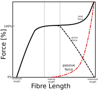
In addition to the active force-length relationship, there is a passive tensile force applied by the muscle when it is stretched beyond its rest length [1]. The passive force is small at first, but increases rapidly as the muscle reaches the limits of its flexibility as shown in Figure 2.3. At the limits of the muscle’s range of motion, the passive force is often larger than the active force. The forces or torques inputted to a golfer model should try to take into account the force-length dynamics of human muscles. It’s unlikely that the reduction in strength due to shortening occurs during the golf swing, but the passive tensile force becomes important as the golfer reaches the limits of their range of motion at the start of the downswing.
Fibre Length
Fo
rc
e [
%
]
100% 0% plateau region ascendinglimb descendinglimb
maximum length resting length minimum length
Figure 2.2: Force-length curve for active portion of a human muscle [1].
Force-Velocity Relationship for Muscles
The second factor which affects the force output of the muscle is the force-velocity rela-tionship. In the most basic form, this relationship states that as the velocity of the muscle contraction increases, the force output decreases. Typically, this relation is described using the Hill muscle model [1],
F = (F0b−av)
b+v (2.1)
where F is the instantaneous force, F0 is the force produced in isometric (stationary)
contraction, v is the current contraction speed, and a and b are constants. This relation-ship leads to the normalized force-velocity relationrelation-ship shown in Figure 2.4. The exact properties of the curve change depending on the muscle’s cross-sectional area, length, and proportion of fast-twitch and slow-twitch fibres, but the general form stays the same [1]. The force-velocity relationship has a significant effect on muscle output and should be accounted for in the development of the golfer model.
Fibre Length
Fo
rc
e [
%
]
100% 0% maximum length resting length minimum length total force active force passive forceFigure 2.3: Full force-length curve for a muscle including passive and active components. The total force line shows how the combination of the passive and active components can produce larger forces than the active force alone. Both components of this force are important to include in the model. [1]
Passive Moments at Joint Limits
In combination with the passive muscle forces describe earlier, passive elastic structure (ligaments, joint capsules, skin, and other surrounding tissues) apply moments to joints to prevent them from leaving their normal range of motion. These passive forces can be very strong and have been shown to be important when modeling human gait [15]. The passive moment begins to affect joints near the limits of their range of motion and grow quickly as the joint goes beyond its normal range to prevent further bending.
Passive joint moments have been measured for many joints in the body and the general shape of the joint angle vs. torque curves is shown in Figure 2.5. The passive moment is small through the normal range of motion and quickly grows outside of those limits. The angle at which the moment is applied and rate of growth differs from joint to joint but the general shape of the applied torque remains the same.
Muscle Activity During the Golf Swing
Of these biological characteristics, the muscle activation dynamics described in Section and shown in Figure 2.1 are the most important factor in controlling the golf swing. They provide limits on the ability of the golfer to control the swing and make control strategies that involve turning muscles on and off frequently difficult. Since the golf drive is an activity where the goal is to achieve maximum distance, it is likely that the muscle groups used are activated for their maximum power production and the golfer’s main role is to control the timing of these activations [16] and thus the timing of the swing.
The passive joint forces that provide limits on joint angles are also important to con-sider when modeling biomechanically possible swings. Especially at the wrist joint, the passive forces prevent the wrist from bending backwards into an anatomically impossible
Figure 2.5: General shape of the passive joint moment [2]. τ is the passive moment andθ is the joint angle. θ1 and θ2 indicate the normal range of motion of the joint.
position during the early portion of the swing while the golfer’s wrist muscles are not ac-tive. In addition, the passive forces are able to store strain energy accumulated during the backswing and provide more power to the swing. Passive forces are a significant part of the stretch-shorten cycle which allows golfers to generate more power in their swing [10].
The force-velocity relationship is also important for the muscles involved in the swing. As the golfer accelerates through the downswing, their muscles will be able to provide less torque to continue accelerating the club. The velocity of the swing is probably not large enough so that no torque can be provided, but the active torque applied is greatly reduced near the impact point.
The force-length relationship will not have a large effect on the muscles during the golf swing. For the range of motion required, the muscle sarcomere lengths will likely be within the optimal range [17].
2.1.3
Club Flexibility
Club flexibility plays an important role in generating clubhead velocity and greatly affects the presentation (orientation) of the clubhead at impact. During the downswing, the clubhead first lags the hands as strain energy is stored in the shaft before whipping forwards to contact the ball. By the time of impact, the club is usually bent forward, leading to increased loft angle of the club face, and possibly an increase in clubhead speed [18]. Figure 2.7 shows the expected flexing pattern for the club throughout the swing in the forward plane.
In addition to lead-lag flexing, the clubhead also droops during the swing to align the centre of mass with the plane of rotation of the swing. The centripetal acceleration of the clubhead tends to push the clubhead centre of mass downwards as the club accelerates.
Figure 2.6: The clubhead droops as it accelerates, bringing the centre of mass closer in line with the plane of the swing and the hands of the golfer. The amount of droop is exaggerated in this Figure to better illustrate the effect.
This effect is illustrated in Figure 2.6. Finally, axial flexibility of the shaft introduces a small amount of lag between the rotation of the grip and the rotation of the clubhead about its vertical axis.
Flexible Club Models
Many attempts to model the flexible club have been made. In 1992, Milne and Davis [18] created a mathematical model for the shaft using a two-dimensional double-pendulum
t = -68 ms t = -127 ms t = -39 ms t = -19 ms t = -4 ms t = 10 ms t = 24 ms 5 0cm -5 5 0cm -5 5 0cm -5 -5 0cm 5 5 0cm -5 5 0cm -5 5 0cm -5 5 0cm -5 t = -229ms
Figure 2.7: The typical flexing pattern of the club during the swing. The amount of shaft bending is magnified by 5 times in this image to make the bending patterns more obvious. Timing information and the amount of bending is taken from Milne and Davis [18].
model of the golf swing. This model used the principle of virtual work to derive a series of shape equations for the shaft. Three golfers’ swings were tracked using optical markers and strain gauges were used to verify the results. The model was used simply to describe club flexing during the swing and it is not suitable for use in a forward dynamic simulation.
Another attempt to model the flexible golf shaft was made by Mackenzie as part of a larger 3-D golfer model [19]. The hands of the golfer, along with the shaft and clubhead (often considered as a single rigid body in many golfer and club models [20] [21] [22]) were divided into 4 subsections, each with its own set of inertial properties. These sections were connected with universal joints that allowed lead-lag and toe-down deflection. To approximate the shaft stiffness characteristics, each joint was fitted with a rotational spring and damper which provided a torque to the joint taking the form:
T = (−Kθ)−(Cω) (2.2)
where K was the stiffness coefficient, θ the angular displacement of the segment, C the damping coefficient, and ω the relative angular velocity of the segment. To find the K values, clubs were tested in a cantilever setup by suspending a 1kg weight at the hozel and measuring the shaft deflection. K values were selected by an optimization process that matched a simulated version of the test setup to the measured results. C values were selected that best matched experimental results. This model is able to account for some changes in stiffness characteristics along the length of the shaft but it cannot account for continuous bending of the shaft or any axial deformations (rotational or translational) that occur during the swing.
A more complete model of the flexible club was proposed by Sandhu et al. in 2010 [23]. This model uses Rayleigh beam theory to model the club and will be described in detail in Section 3.2. Using Rayleigh beam theory allows for continuous bending and continuously
varying stiffness properties along the length of the shaft. Sandhu used this model as part of a kinematically driven forward dynamic golf club model and was able to achieve good matches with the dynamic loft and droop of experimental results.
2.1.4
Impact
The impact portion of the golf swing is confined to a very short period of time (5 mi-croseconds or less) so it is impossible for the golfer and shaft to have an effect on the clubhead during the impact time. Therefore, the shaft dynamics and the golfer’s actions and dynamics can be ignored during the impact phase and the clubhead assumed to be moving freely during the impact [8]. The impact can be considered as an oblique impact between two 3-D bodies. The results of this impact, the initial conditions of the ball’s velocity and spin during its flight, are dependent on the physical and geometric properties of the clubhead and ball, the orientation of the clubhead, the velocity of the clubhead, and the relative positions of the two bodies at impact. This Section will describe the impact of the golf club and the ball and explain how the mechanics of that impact are affected by changing these parameters.
Clubhead Orientation
The clubhead orientation changes two features of the impact. First, the dynamic loft of the clubface (the angle between the face of the club and a vertical plane at the point of impact) affects the vertical launch angle and the amount of backspin of the ball following the impact. Increasing the loft increases the launch angle and the amount of backspin. The dynamic loft is a combination of the nominal loft of the club (usually 9° to 11° for a driver) and the additional loft created by the flexing of the club shaft as described in
CG Location CG Location
Figure 2.8: Top view of an open clubface orientation (left) and a closed clubface orientation (right).
Section 2.1.3. The dynamic loft can be adjusted by placing the ball further forward in the swing, selecting a club with greater nominal loft, or increasing the flexibility near the tip of the shaft. The amount of loft that is ideal depends on the individual swing and varies from golfer to golfer.
Second, the opening/closing angle of the club face has an important effect on the horizontal launch angle and the amount of side spin on the ball after impact. At impact, due to the moment of inertia of the club about the shaft axis, the clubface tends to be tilted backwards away from the golfer in an open position. This results in a slice spin on the ball and a horizontal launch angle away from the golfer. In similar fashion if the clubface is closed at impact, there is a resulting hook spin and launch angle towards the golfer. Since it is more common for a golfer to hit from an open position, golfers intentionally work to close the clubface at impact through the pronation of the arm. Ideally, the clubface is perpendicular to the ball at impact, resulting in a straight shot with minimal side spin. Figure 2.8 shows the open and closed clubface orientations.
Centre of Mass Alignment
The alignment of the centre of mass of the golf club with the centre of mass of the ball changes both the launch angles and the spin of the ball after impact. If the centre of masses are perfectly aligned with the velocity vector of the club, this is a perfect strike of the ball and the launch velocity will be entirely forward and upward with very little side spin.
More interesting is what happens when the ball is struck off-centre, with an eccentric impact imparting angular momentum to the clubhead and ball. The spin of the ball after such an impact comes from two sources: the tangential forces at the impact point, and the gear effect between the clubhead and ball. Figure 2.9 illustrates this scenario, showing a toe hit. In the figure, the impact location of the ball outside the centre of mass of the clubhead causes the clubhead to rotate clockwise as indicated. In a normal eccentric impact, this impact location would also lead to the ball spinning clockwise (opposite to the indicated direction) and for the shot to slice, but the gear effect changes the result. The contact point on the club face moves in the direction shown on the diagram and as the ball rolls on the face of the club, the ball is caused to spin in the opposite direction to the club. For a toed shot, there is resulting hook spin, and for a heeled shot, there is a resulting slice spin. This effect is known as the “gear effect” because the club face and ball act as two gears spinning in opposite directions.
The gear effect also affects the backspin of the ball for an impact that is out of alignment in the vertical direction. If the ball strikes high on the face the backspin is reduced and if the ball strikes low the backspin is increased.
Figure 2.9: Illustrating the “gear effect” for a toed shot.
Clubhead Properties
Four properties of the clubhead have a significant effect on the impact and are therefore limited by the rules of the US Golf Association (USGA). The clubhead mass is important as it helps determines the amount of energy and momentum that is available during the impact. If the mass of the clubhead is increased and its velocity stays the same, the ball will be launched at greater speed following the impact. The mass of the clubhead is not directly limited by the USGA, but most drivers have a clubhead mass of about 200 g.
The moments of inertia (MOI) of the clubhead have a more interesting role in deter-mining the spin of the ball following impact. Because of the gear effect described above in Section 2.1.4 the amount of angular velocity imparted to the clubhead by an off-centre strike is important in determining the spin of the ball. By increasing the MOI about the vertical axis, the spin imparted to the club by an off-center hit is reduced and therefore
the side spin on the ball is reduced [24]. This helps reduce the hooking or slicing effect of an off-center hit. To prevent golf clubs with extremely high MOI from being produced, the USGA has limited the MOI of a golf club about its vertical axis through the centre of mass to 5900 g cm2 [25].
The elasticity of the club face controls the energy lost due to deformation when the ball and club collide. To increase the distance of the drive, club manufacturers try to increase the flexibility of the face so that the natural frequencies of the ball and club match as closely as possible to produce a ”trampoline effect” that minimizes the energy lost [26]. To limit this effect, the USGA has also limited the elasticity of the clubface by limiting the contact time to 239 ± 18µm as measured by striking the club face with a particular mass and pendulum [25]. The measured contact time is directly related to the compliance of the clubface. Increasing the coefficient of restitution (CoR) by increasing the elasticity of the club face results in higher ball speeds after impact and longer drives.
Finally, the bulge and roll of the club face change the launch angles of the ball to produce straighter shots from off-centre hits. Since hitting the ball off-centre horizontally results in a slice or a hook spin due to the gear effect, the bulge of the clubface causes the ball to have an initial velocity in a direction opposing the motion that will be caused by that spin: e.g., for a toe hit which results in a hook spin the ball is initially launched with some velocity away from the golfer to reduce the effect of the hook. Similarly, the bulge of the club increases the vertical launch angle for hits above centre and decreases it for hits below centre.
Clubhead Velocity
By increasing the clubhead velocity, the ball will be launched at greater speeds. In fact, the clubhead velocity is the single greatest determining factor in the distance the ball will carry [20]. Increasing the clubhead velocity will make the effects of off-centre hits larger as the greater impulse in the collision leads to increased side spin.
2.1.5
Ball Aerodynamics
The aerodynamic flight of the golf ball is dependent on the initial velocity of the ball and the spin of the ball as it travels through the air. While the initial velocity is most important for the total distance the ball flies with greater velocity producing greater distance, it is the spin of the ball which has the most interesting effects on its flight path. The Magnus effect of the spin of the ball produces both lateral and upward lift forces during its flight [27]. In golf, these forces are influential in two ways.
First, the direction and amount of side spin (about the vertical axis of the ball) affects the sideways motion of the ball during its flight. As viewed from the top, clockwise spin causes the ball to ’slice’ to the right and counter-clockwise spin causes the ball to ’hook’ to the left [28] as shown in Figure 2.10. Sometimes side spin is intentionally applied to the ball to produce a particular trajectory but in general side spin has an undesirable effect on the shot and decreases the distance the ball will fly.
In contrast, backspin can increase the carry distance by providing lift to the ball during its flight. Increasing the backspin increases the amount of lift on the ball, but there is an upper limit to the amount of lift that can be usefully applied. If there is too little backspin on the ball, no lift is applied to the ball and the flight path is parabolic, like
Figure 2.10: Top view of the effect of side spin on the flight of the golf ball. The top path is a ’hook’ shot for a right-handed golfer and bottom path is a ’slice.’
that of non-spinning projectile as seen in Figure 2.11a. If there is too much backspin (see Figure 2.11b) the excess lift causes the flight path of the ball to balloon upwards, reducing the carry distance. In addition, this flight path leads to a higher angle of impact with the ground, reducing the distance the ball will roll. With the ideal amount of backspin (see Figure 2.11c) the ball rises on a high, boring, trajectory during its flight, carrying further downrange. The ideal amount of backspin depends on the launch velocity and angle of the ball, but in general higher velocity trajectories require less backspin to maintain the optimal trajectory [29]. One club manufacturer has stated that the optimal amount of backspin is 1700 rpm [30].
(a) Typical flight path of the golf ball for a low backspin shot. Notice how it follows a parabolic path. There is no lift provided by the spin.
(b) Typical flight path of the golf ball for a high backspin shot. Too much lift causes the flight path to balloon upwards, reducing the carry and reducing the roll after hitting the ground.
(c) Typical flight path of the golf ball for a shot with a good quantity of backspin. Note the boring trajectory that leads to a non-parabolic flight path and the increased carry distance.
Figure 2.11: Flight paths of the ball illustrating the effect of backspin on the flight of the golf shot.
2.2
Golf Driver Design
Designing a golf driver requires the balancing of many factors within the framework dic-tated by the rules of the US Golf Association (in the USA and Mexico) and the R & A (worldwide). While the rules of the game provide hard constraints on several aspects of the design of the club, there remain many trade-offs to be made in the design process. Each year, club manufacturers release new clubs and make new claims about the scientific im-provements they have made that will allow golfers to hit the ball further and straighter. In this section, several different design decisions and manufacturers claims will be described along with the possible and expected outcomes of those decisions. These decisions and claims will be revisited and analyzed within the context of the model presented in Chapter 3 in Chapter 4.
2.2.1
Club Mass
One of the more recent claims of golf club manufacturers is that a lighter club would result in longer drives [31]. The claim made was that by decreasing the club mass 10 g, the golfer would be able to swing the club 1 mph (0.45 m/s) faster, resulting in longer drives. The trade off here is that by decreasing the club mass, the momentum of the club is not necessarily increased overall by an increase in clubhead speed and the momentum of the clubhead before impact that controls the amount of energy that can be transferred to the ball. It is likely that there is a sweet spot for club mass for each individual golfer and finding that spot is one of the challenges in designing a club.
2.2.2
Clubhead Moment of Inertia
Due to the gear effect of the ball interacting with the club (see Section 2.1.4, the amount of angular velocity imparted to the clubhead during impact is important in determining the side-spin of the ball. By increasing the moment of inertia (MOI) of the clubhead, the angular velocity of the clubhead is reduced and the amount of spin imparted to the ball is similarly reduced. By increasing the MOI of the clubhead about its vertical axis, manufacturers have created drivers that can hit the ball straighter for off-centre impacts on the club. This led to the creating of a rule by the USGA that no club may have a MOI greater than 5900 g cm2 [25].
Even without this rule, improvements to the club made by increasing the clubhead MOI were shrinking as the increase in MOI makes it more difficult for the golfer to close the clubface at impact. Since the MOI is larger, more torque is required from the forearms and hands to rotate the club to the appropriate angle. There is clearly a tradeoff between increasing the MOI to reduce the spin and decreasing the MOI to increase the controllability of the club.
2.2.3
Clubhead Centre of Mass Position
The ideal centre of mass position of the clubhead is also a matter of debate. While most people agree that then the centre of mass of the clubhead should be low, to decrease the amount of backspin on the ball, it is unclear whether it should be low and close to the clubface or low and far from the clubface. In particular the TaylorMade SLDR driver released in 2013 claimed that a low and forward centre of mass location would provide better launch conditions.
The centre of mass should be low so that the gear effect of the ball striking above the centre of mass reduces the backspin of the ball as most golfers tend to hit with too much backspin for an optimal flight (see Figure 2.11b). Striking above the centre of mass causes the clubface to rotate upwards and reduces the backspin on the ball. Moving the centre of mass forward or backwards normal to the clubface should not change this effect as the moment arm of the impact force will not change. It’s unclear whether this movement might have other effects and this should be further investigated. Moving the centre of mass forward horizontally relative to the ground should reduce the backspin as the moment arm of the impact will be increased.
2.2.4
Shaft Flexibility
The shaft of the golf driver bends forward at impact so that the clubhead strikes the ball while angled slightly upwards. This can help to reduce the backspin of the ball and increase the launch angle to improve the carry. The common wisdom is that a golfer with a faster swing speed needs to use a stiffer club and a golfer with a slower swing speed should use a more flexible club. It’s important for a golfer to select the correct shaft flexibility for their particular swing and this selection is one of the parts of a traditional shaft fitting performed by a golf pro.
While shaft flexibility does not involve design trade offs in the traditional sense the selection of the appropriate shaft can be difficult and deserves consideration. Any single shaft is unlikely to be correct for all golfers, but the question of fitting a shaft for a particular golfer is an interesting one. In a world where more goods will be personally manufactured for individual consumers the possibility of designing the shaft flexibility directly for one particular golfer using a computer model is attractive. While the model
presented in this paper is not subject-specific it can be used for testing different flexible shafts and optimizing the stiffness.
2.3
Golfer Models
2.3.1
Early Golfer Models
Cochran & Stobbs
Search for the Perfect Swing, first released by Cochran and Stobbs in 1968, was the first
serious scientific study of the golf swing [8]. They developed a planar double-pendulum model for describing the golf swing where each of the joints is powered by a rotational spring that is loaded during the backswing and released during the downswing. They were the first to propose the idea that the relative timing of the torques applied to each link in the kinematic chain of the golf swing was crucial to a successful, powerful, swing and the importance of swinging in a planar manner. They compared their model to stop-motion photography of golfers and found that it was a reasonable fit for real golf swings. In the same study, Cochran and Stobbs also analyzed a number of other scientific aspects of golf such as shot strategy and putting, but these are not relevant for this work.
Lampsa - Golf Swing Optimization
One of the earliest attempts to optimize the golf swing was made by Lampsa in 1975 [20]. Lampsa made use of a planar double-pendulum model of the golf swing to investigate the optimal control aspect of the golf swing. By applying Pontryagin’s Minimum Principle to the joint torques applied to the double-pendulum model, Lampsa attempted to optimize
the golf swing for maximum clubhead speed while maintaining biologically feasible joint angles. The joint torques found through the optimization were dissimilar from those found from inverse dynamics. Lampsa concluded that it should be possible to hit the ball much further without increasing the golfer’s strength and that the key to longer drives would be to delay uncocking the golfer’s wrists as long as possible to generate greater clubhead speed. Lampsa’s study also performed a sensitivity analysis of changes to the club, varying the mass of both the clubhead and shaft by 10 % to determine the effects on the optimal swing. The conclusion was drawn that changing these parameters has little effect on the optimal torques and results in at most a 1.3 % change in the optimal clubhead speed at impact.
2.3.2
Modern Golfer Models
Sharp - Parameterized Joint Torques
A more recent influential model of the golf swing was proposed by Sharp in 2009 [22]. Sharp compared the typical rigid double-pendulum model of the golf swing with a rigid triple-pendulum model and concluded that including the rotation of the torso and shoulders as part of the swing allowed for a significant improvement in matching captured experimental data. In particular, the triple pendulum model allows for more range of motion in the backswing and a fuller golf motion during the downswing. Sharp concluded that the double-pendulum model of Lampsa was insufficient and created a new forward dynamic model for the swing.
One of the main innovations of this model was the inclusion of parameterized joint torques as inputs to the model to allow some flexibility for the inputs while simplifying the optimization of the swing. The shapes of the torque functions were selected to provide
reasonable matches to inverse dynamics results obtained through testing of a few highly skilled golfers. Three joint torques were required and a different form was used at each joint. The torque provided to rotate the shoulders was
Ts =Tsmaxtanh (λt)−τs2(t−ts)H(t−ts) (2.3)
where Tsmax is the maximum exertion level, τs2 defines the linear drop-off in torque, ts is
the drop off start time, andH(x) is the Heaviside step function. The torque to rotate the arm about the shoulder was given by
Ta= min(τa1t, Tamax)−τa2(H(t−ta)(t−ta)) (2.4)
where Tamax is the maximum exertion level, τa1 defines the linear increase in the torque
at the start of the swing, and τa2 defines the linear decrease in the torque after time ta.
Finally the wrist torque was defined as
Tw =Twmaxtanh(λ(t−tw)) (2.5)
giving a negative maximum torque (Twmax) at the start of the simulation, followed by a
switch to a positive maximum torque after time tw.
Sharp also included passive joint torques in the form of linear spring-dampers at extreme joint angles. The passive joint torques are 0 until the limits are reached and are then activated.
By optimizing the parameters in the joint torque functions, Sharp was able to fit the triple pendulum golfer model to real swings of 3 different highly skilled golfers with good agreement. He then tried optimizing the swing to produce the maximum clubhead speed. Contrary to Lampsa’s earlier results, the optimal torque did not show a holding-back phase for the wrist. Changing the strength of the golfer did not change the general patterns of the swing, but did increase the clubhead speed at impact.
Mackenzie - A Biomechanical Model
Mackenzie’s golfer model, published in 2009 also used the concept of parameterized joint torques to improve the feasibility of optimizing the golf swing [16]. He also introduced a version of the triple-pendulum model that allows for 3-dimensional motion during the swing. Instead of just swinging in a single plane, Mackenzie added an extra degree of freedom along the long axis of the golfer’s left arm to allow supination and pronation of the wrist during the swing and added a separate plane of rotation for the shoulders and arms during the swing. Mackenzie’s parameterized joint torques will be described in detail in Chapter 3 but in short, they allow for the same biologically-motivated parameterized torque to be used at each joint.
In Mackenzie’s model, the shaft of the club was split into four sections with a spring and damper at each joint to model the flexibility characteristics of the shaft. A number of golf clubs were subjected to a flexing test and the stiffness parameters selected to best match the shape of the club as measured in the test. This approach allows for flexing of the shaft at a few points along its length, but cannot model continuously varying shaft properties or bending.
Like Sharp, Mackenzie also used parameter optimization to attempt to find the best possible swing. Genetic algorithms were used to pick the best possible activation and deac-tivation times for the muscles using the clubhead speed as the objective function. Penalties were added to avoid improper clubhead presentation. The final maximum clubhead speed achieved by Mackenzie was 41.7m/s.
2.3.3
Other Golfer Models of Interest
Other golfer models created over the last 50 years with many different goals and purposes were examined during this work. A few of them with interesting details will be described in this section. Many of these models included ideas that were incorporated into the final model proposed in this paper.
Reyes and Mittendorf applied the fixed double-pendulum golfer model to the swing of a long drive champion [21]. Unlike other studies, instead of just studying clubhead velocity, an impact and carry model was used along with the golfer model to determine possible changes to the swing to improve the distance. Increasing the backswing angle, wrist angle, or changing to a lighter clubhead were the areas identified by the model as offering the greatest change in clubhead speed. Ball carry was not affected by using a lighter clubhead as the effect of using the lighter club on the impact reduced the carry.
Nesbit [32] and Serrano [33] created a full-body model of a golfer and used inverse dynamics to study the swings of 1 female and 84 male golfers. He found significant subject to subject variation in the swing, even among skilled golfers. More skilled golfers are able to increase their club speed not by applying greater force, but through increased range of motion. They do more work during the swing, and have a higher peak power output during the swing. Power peaks slightly before impact during the swing and most of the power output is provided by the torso and shoulder rather than the wrists or hands. The amount of strain energy stored by the club is minimal compared to the total work.
Betzler’s thesis [34] examined the effects of changing the staff stiffness on the biome-chanics of the swing using a motion capture system. Two different levels of club flexibility were tested by a group of twenty skilled golfers. Decreasing the flexibility of the shaft increased the clubhead speed significantly, due to increased recovery of the stiffer shaft
from lag bending. The face angle and impact location were unaffected by shaft flexibility. Similar tests were performed with a golf robot and the results confirmed. It seems that golfers are able to adapt to different club flexibilities to hit the ball well but there may be some difference in the distance of shots achieved.
Kenny [35] created a full-body golfer model with 42 degrees of freedom that was driven by experimental data from a single golfer. This golfer-specific model was used to analyze the kinetic energy of the kinematic chain of the golf swing. He found that the while the kinetic energy increased from proximal to distal body segments, there was no sequential ordering to the peaks in each body segment. Kenny concluded that each individual golfer would likely have a unique profile to their golf swing. It will be important to accommodate this variability into any golfer model produced.
Hauefle [36] investigated the effect of changing the mass of the club through simulation and experiment. Using the double-pendulum model of Pickering [37] with two different club models, it was found that increasing the club mass by 22g resulted in a swing that was 1.7% slower. In contrast, experimental results for actual golfers did not show a predictable change in club speed with a heavier club. This showed the golfers respond to changes in the golf club by changing they way that the club is swung, instead of swinging the same way with every club.
2.4
Opportunities
Despite all of the work already done in this field, there remain significant opportunities for creating an improved golfer model that allows for new questions to be asked and answered. In particular a model which can include the following features would be valuable:
Forward dynamic model capable of answering ‘what-if’ questions regarding changes to the club and golfer.
Golfer model including a non-planar model of human motion, active joint torques that act similarily to human muscle, and passive joint torques that mimic the storage of energy during the backswing of the golfer.
Flexible club model capable of predicting droop, dynamic loft, and clubface presen-tation.
Impact model and aerodynamic model for evaluating each swing.
Optimization strategy that allows the model to swing optimally in a variety of con-figurations.
Such a model would be able to answer questions that have been asked recently about club design including how to distribute flexibility along the length of the shaft, whether a lighter club can really hit the ball further, and where the centre of mass of the clubhead should be positioned.
The model presented in Chapter 3 of this thesis accomplishes the goals stated here and the experiments in Chapter 4 try to answer some of the questions posed. These questions represent just the first of many that could be answered using this model.
Chapter 3
Golfer Model
To simulate the golfer and club and take advantage of the opportunities described in Section 2.4 a four-part model was constructed. The parts are
1. Biomechanical golfer model with parameterizable joint torques
2. Flexible club model including club aerodynamics
3. Impact model of the club and ball
4. Aerodynamic model of ball flight
This Chapter will describe each portion of the model and its implementation in detail.
3.1
Biomechanical Golfer Model
The golfer portion of the mathematical model consists of three rigid bodies representing the torso, left arm, and left hand of the golfer. There are four degrees of freedom for the
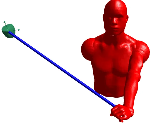
golfer. The first degree of freedom is the rotation of the torso. This represents the rotation of the shoulders during the golf swing and is activated by the power of the muscles of the legs and core. The second degree of freedom allows transverse flexion and transverse adduction of the shoulder across the front of the body. The third degree of freedom allows supination and pronation of the arm and the final degree of freedom allows for ulnar and radial deviation of the wrist. These four degrees of freedom are illustrated in Figure 3.1. This golfer model, based on the work of Mackenzie [16] was considered to be sufficient to apply the correct kinetics to the golf shaft throughout the swing. A discussion of the limitations of the model can be found in Section 4.8.
Four degrees of freedom are sufficient to provide the model golfer with the range of motion required for the swing. The golfer begins the swing with the torso rotated backwards (away from the target), the shoulder maximally adducted, the wrist maximally deviated towards the radius, and the arm pronated so that the club extends over the golfers right shoulder towards the target. During the swing, the torso rotates forward, the arm extends across the body, the wrist fully deviates towards the ulna and the arm supinates to square the face of the club towards the ball. A three body-model of the golfer is sufficient to capture the main dynamics of the swing.
The mass and inertia properties for the torso and arm of the golfer were taken from the work of Mackenzie [17] and are shown in Table 3.1. The mass and moment of inertia of the hand also takes into account the mass of the grip of the shaft and is also shown in Table 3.1. The segment geometries are shown in Table 3.2. Finally, the golfer’s torso was inclined from the vertical by 30 degrees and the swing plane of the arms was inclined 50 degrees. Separate planes of rotation for the shoulder and arm rotation are better able to mimic the swing of a human golfer than single-plane models [14].
Segment M ass (kg) Ixx (kg cm2) Iyy (kg cm2) Izz (kg cm2)
Torso 34.61 ... 3655 ...
Arm 3.431 1076 1096 58.06
Hand & Grip 0.6 10.24 10.24 6.04
Table 3.1: Segment mass properties of the golfer.
Segment Length (cm) CM Locx (cm) CM Locy (cm) CM Locz (cm)
Torso 20 0 0 0
Arm 60 0 0 26.1
Hand & Grip 20.0 0 0 9.0
Table 3.2: Segment geometry properties of the golfer.
3.1.1
Active Muscle Torques
Inputs are provided to the model at each degree of freedom in the form of parameterized joint torques. When designing these input torques, a number of factors were taken into account. The goals for the selection of these torques were:
To provide realistic biologically-inspired inputs to the model;
To capture the relevant muscle dynamics (described in Section 2.1.2) in producing the torques;
To contain the inputs within biological limits;
To parameterize the inputs so that the optimal control of the swing can be performed easily; and
To use the same form for the torque at each degree of freedom.
To accomplish these goals, the parameterized torque functions proposed by Mackenzie were chosen as the active inputs to the model [38].
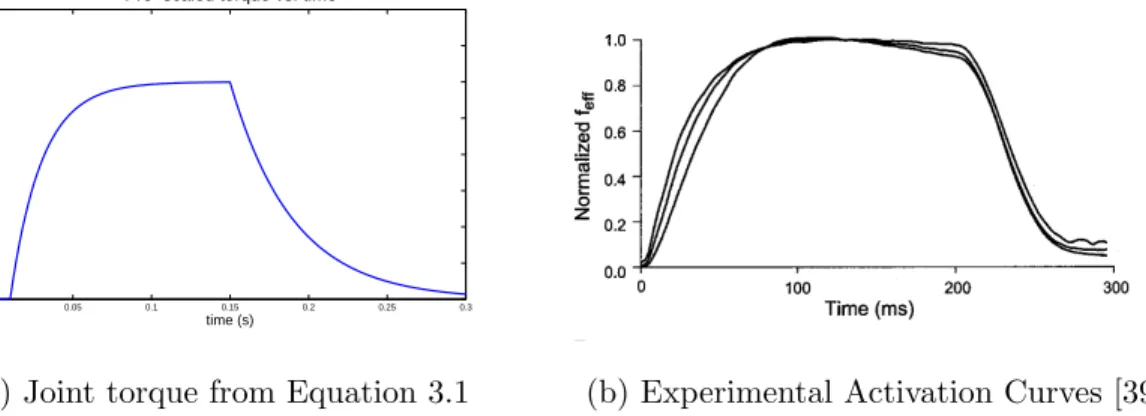
In this method, a two step calculation is used. In the first step, it is assumed that the golfer attempts to apply a maximum joint torque instantaneously for some time and then stops applying that torque. As muscles are unable to produce instantaneous torque due to the dynamics discussed in Section 2.1.2 the applied torque ramps up and ramps down as it is activated and deactivated. The equation used to describe step 1 is
Tpre(t) =Tm(1−e
ton
τact)−Tm(1−e
toff
τdeact) (3.1)
where Tm is the maximum possible applied torque, τact is the time constant of activation,
and τdeact is the time constant of deactivation. ton and tof f are the amount of time that
has passed since the torque was activated and deactivated respectively and are calculated as piecewise ramp functions.
ton(t) = 0 :t < tactivate t−tactivate :t > tactivate (3.2) tof f(t) = 0 :t < tdeactivate t−tdeactivate :t > tdeactivate (3.3)
wheretactivate is the time at which the joint torque is activated and tdeactivate is the time at
which it is deactivated.
The second step in generating the active torque component is to perform scaling based on the current velocity of the muscles involved. The scaling performed is based on the Hill muscle model described in Equation 2.1. By manipulating this equation, we can reach a
0 0.05 0.1 0.15 0.2 0.25 0.3 0 10 20 30 40 50 60 70 80
Pre−scaled torque vs. time
time (s)
torque (Nm
(a) Joint torque from Equation 3.1 (b) Experimental Activation Curves [39]
Figure 3.2: A comparison of muscle torques generated by Equation 3.1 to a typical muscle activation curve.
point where all of its components are easily determined biologically.
F = (F0b−av) b+v F = F0 b− a F0 b+v F = F0 F0b a −v F0b a + F0 a v (3.4)
This seems more complicated, but each of the inner fractions can be replaced with a more descriptive, biologically relevant, form. First F0b
a can be replaced by vmax, the
maximum velocity at which the muscle is still able to exert force [1]. And second, the inverse of the second fraction, Fa
0, has been measured in experiments to be close to 0.25 for
mammalian skeletal muscles [1]. Replacing F0
a with the parameter Γ, we arrive at a scaling
equation for the muscle force.
F =F0
vmax−v
vmax+ Γv
Figure 3.3: Sample joint torque curve incorporating velocity scaling
Assuming that we can transform this equation from the translational (muscle force) to the rotational (joint torque) domain using constant length moment arms, and including the activation curves from Equation 3.1, the active portion of the joint torque is then generated in the same manner as Mackenzie [16].
T(t, ω) = Tpre(t)
ωmax−ω
ωmax+ Γω
(3.6)
A sample curve showing the active portion of the joint torque for the torso during a swing can be found in Figure 3.3.
This approach was selected because it accounts for both the activation dynamics and the force-velocity relationship for the muscles while keeping the number of control parameters small. Since the maximum torque, activation constants, and shape parameters remain constant across swings, only the activation timings need to be determined for each torque generator in the model. This results in 8 muscle parameters that must be chosen during the optimization process, a manageable number.
For each joint, the maximum torque provided (Tm) and the maximum angular velocity
Generator Tm (N m) τact (s) τdeact (s) ωmax (rad/s) Γ
Torso 200 0.02 0.04 30 4.0
Shoulder 160 0.02 0.04 30 4.0
Forearm 90 0.02 0.04 60 4.0
Wrist 90 0.02 0.04 60 4.0
Table 3.3: Parameters for the four active joint torque generators.
3.1.2
Passive Muscle Torques
To account for the torques applied to the golfer’s joints at the limits of their range of motion (e.g., at the start of the downswing) and to keep the joints of the model within the normal range of human motion, passive joint torques are applied to each degree of freedom at the limits of its acceptable range. Passive joint torques are included for the torso, shoulder and wrist, and represent the energy stored during the backswing. To model this sort of passive force, Yamaguchi [2] proposed the use of Equation 3.7.
Tpassive(θ,θ) =˙ k1e−k2(θ−θ−)−k3e−k4(θ+−θ)−c1θ˙ (3.7)
This function is able to approximate the restoring moment at both extremes of the joint range of motion and offer a smooth transition in joint torque from the normal range of motion, where very little torque is applied, to the large moments applied at the edges. The constantsk1 and k3 govern the magnitude of the force at the breakpoints (θ− andθ+)
whilek2 and k4 govern the sharpness of the break. For this form,θ− and θ+ should be set
well within the range of motion of the joint.
For each joint with a passive component, the values k1, k2, k3, k4, θ− and θ+ must
Figure 3.4: Contour plot illustrating the passive torques for the shoulder joint [3].
ankle, knee, and hip moments [2] [15] [40] but no values for the upper body were found. Instead, the parameters were determined from experimental data.
Engin [3] performed experiments to determine the passive moments of the shoulder complex for its full range of motion resulting in a contour plot like Figure 3.4. To find the parameters for Equation 3.7 a point for each contour in Figure 3.4 was extracted at the appropriate sagittal angle and the Matlab commandnlinfitused to find the appropriate values. The same process was repeated for the wrist joint using data from [41], for the torso using data from [42], and for the forearm pronation/supination using data from [43]. The damping coefficient c1 was set to 0.1 as suggested by Yamaguchi [2].
Plots showing the experimental data and the fitted curves using Equation 3.7 are shown in Figure 3.5 and the extracted parameters are given in Table 3.4.
![Figure 2.2: Force-length curve for active portion of a human muscle [1].](https://thumb-us.123doks.com/thumbv2/123dok_us/11084351.2995184/23.918.294.637.179.497/figure-force-length-curve-active-portion-human-muscle.webp)
![Figure 3.4: Contour plot illustrating the passive torques for the shoulder joint [3].](https://thumb-us.123doks.com/thumbv2/123dok_us/11084351.2995184/57.918.294.632.185.464/figure-contour-plot-illustrating-passive-torques-shoulder-joint.webp)
![Figure 3.6: Flexible beam model as proposed by Shi et al. [4].](https://thumb-us.123doks.com/thumbv2/123dok_us/11084351.2995184/61.918.129.811.358.766/figure-flexible-beam-model-proposed-shi-et-al.webp)