The Rationale of Powertype-based Metamodelling
to Underpin Software Development Methodologies
Brian Henderson-Sellers and Cesar Gonzalez-Perez
Department of Software EngineeringFaculty of Information Technology University of Technology, Sydney PO Box 123, Ultimo 2007, NSW
[email protected]; [email protected]
Abstract
Metamodelling provides a way of modelling the rules underpinning not only modelling languages such as UML but also processes. In the context of object-oriented development, we evaluate the conceptual framework used to reason about metamodelling from the different perspectives of methodologist, method engineer and software developer. We propose the use of clabjets and powertype patterns as a solution to avoid the present inconsistencies in the use of a strict metamodelling multi-level hierarchy and demonstrate their efficacy in providing a solid and improved framework for OO-based process (and product) metamodelling.
Keywords: Metamodelling. Powertype. Software development methodologies.
1
Introduction
We can define metamodelling as the subject dealing with the creation, maintenance and application of metamodels , where a metamodel is defined as a model of a model Atkinson and Kühne (2003). If this is accepted, then a metamodel should contain the structure and, optionally, behaviour necessary to represent some target model, as any regular model contains the structure and, optionally, behaviour necessary to represent some target system. That is to say, a metamodel is a regular model in which the subject under study happens to be a model rather than any other kind of system Seidewitz (2003). Metamodels can, in theory, represent any kind of model, but this paper focuses on metamodels that represent conceptual models of software systems and the processes necessary to construct them.
The main objective of any conceptual model is to represent some subject under study by discarding unnecessary detail and keeping only the relevant information. Therefore, in our chosen context, the main objective of a metamodel is to represent a conceptual model of a software system and the processes necessary to construct it. Such representation ===========================
Copyright © 2005, Australian Computer Society, Inc. This paper appeared at the Second Asia-Pacific Conference on Conceptual Modelling (APCCM2005), University of Newcastle, Newcastle, Australia. Conferences in Research and Practice in Information Technology, Vol. 43. Sven Hartmann and Markus Stumptner, Eds. Reproduction for academic, not-for profit purposes permitted provided this text is included.
must be faithful enough to be useful. When a metamodel engineer constructs a metamodel, he/she must keep in mind that this metamodel will be used for practical purposes, so the quality of the representation embedded in it must be optimal. In turn, what is good quality in a metamodel and what is not is determined by the specific usage for which the metamodel has been designed. In this paper, we focus on metamodels designed to be used as frameworks for the definition of software systems and software processes. The main problem posed by metamodelling is, therefore, how to find a way to maximise the quality of a metamodel from the perspective of its users. A metamodel that is theoretically elegant but practically useless could be regarded as of poor quality. The next section describes a conceptual context useful to reason about metamodelling, which is used in Section 3 to tackle the issue of solving the aforementioned problem. Section 4 presents other alternatives to metamodelling and shows how a powertype-based approach is superior. Finally, Section 5 presents the conclusions.
2
A Conceptual Framework to Reason about
Metamodelling
Software developers do not interact with metamodels very often. On the contrary, they work in a world of models, documents, tools and lists of “to-do” tasks. During their daily routine, software developers often execute tasks and use tools to create and modify documents and models. All these activities must be appropriately connected, organized and planned in order to produce a working final product on time and within budget. The body of knowledge comprising the necessary guidance to achieve this can be called a methodology or method (these terms are used in this paper as synonyms). Methodologies combine both product support (related to models and their documentation) together with process support Rolland et al. (1999). Therefore, we can say that methodologies guide software developers in their daily work. This guidance is given as a collection of specifications of the tasks and products that software developers are supposed to be concerned with; for exa mple, a given methodology might describe the specific steps that should be taken in order to obtain the requirements for a system, or list the sections that any system requirements specification document should contain. Software developers apply these specifications to their jobs, thus following the methodology.
It is easy to recognise that the specifications in a methodology comprise a model of the work actually performed by software developers. Also, when software developers use this model as a guide in their daily work, they are in fact enacting the model for the sake of a specific project or endeavour. Enacting means, in this context, creating a real instance of the model given by the methodology. This instance, at least in theory, must comply perfectly with the specifications provided by the model. The quality of a methodology will be given by its capability to generate useful instances.
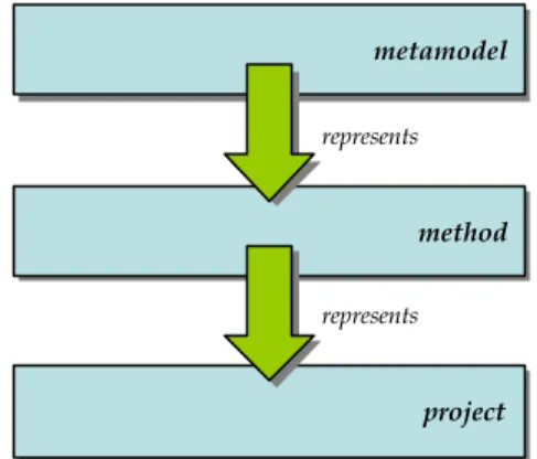
There is a conceptual boundary between the methodology, which specifies what must be done and how, and the enacted instance of it, which actually does something. Software developers cross this conceptual boundary when enacting a methodology on a specific project. In order to separate these conceptual levels, we will call a methodology plus all the specifications contained in it the method layer, and we will call specific instances of a methodology, applied to specific projects or endeavours, the project layer (Figure 1). The relationship between these layers is one of representation: the method layer represents (or models) the project layer so project layers can be created from the method layer when necessary.
metamodel metamodel method method project project represents represents
Figure 1. The proposed metamodelling architecture.
A similar situation can be found between methodologies and metamodels. When a method engineer creates a methodology, they usually utilise a given metamodel from which to create a specific instance, namely the methodology. Metamodels, in this context, serve as guidance to method engineers by providing a collection of specifications that represent potential elements in the methodology. For example, a metamodel can establish that software process lifecycles can be composed of different stages, and that models and documents can be created or modified by tasks. When a method engineer creates a specific methodology using this metamodel, they will decide what specific stages will be included in the lifecycle and what specific models and documents will be created and modified by each possible task specification. The method engineer is using the metamodel as a guide for the construction of a methodology. This involves crossing a new conceptual boundary between the metamodel and the methodology created from it. To the already defined method and project layers, we must add the metamodel layer (top layer in Figure 1), comprised of a metamodel and all the specifications contained in it. Consistent with
the well-established philosophical descriptions of levels of abstraction (e.g. Gershenson 2002), layered architectures similar to this are often used in software-focussed metamodelling approaches such as SPEM OMG (2002b), OPEN Firesmith and Henderson-Sellers (2002) or MOF OMG (2002a) and underpin current initiatives in MDA (see, for example, Kleppe et al. 2003).
Different people work at different layers, and relate to them differently. Method engineers use metamodels (they don’t change them, just use them) to create and extend methodologies. Software developers use methodologies to generate projects and software systems. Methodologies, therefore, serve as a bridge between metamodels and projects, and provide the only and indirect interaction between a software developer working on a project and the metamodel that was used to create the methodology being followed.
We must make a final note before proceeding to introduce and then solve a number of problems associated with traditional metamodelling in the context of software development, particularly object-oriented software development. The discussion presented in this paper is based on conventional object-oriented knowledge and makes use of well-known object-oriented concepts and mechanisms. We have adopted this approach, rather than inventing new concepts and/or mechanisms, to ensure the best degree of understandability and implementability with existing technologies.
3
Solving the Metamodelling Problem
Since we have defined the problem of metamodelling (how to optimize its quality for practical use) from a very applied and pragmatic perspective, we will use the same kind of perspective to reason about the problem and find a way to solve it. This leads us to approach the problem from the bottom, from the optimal result that is desirable, and work towards the top, towards the definition of the best metamodel that could possibly generate such a result.
3.1
The Software Developer’s Perspective
Software developers want a methodology that can be easily enacted on a particular project. That means having a methodology that provides appropriate specifications for all the necessary components of a project, both process-wise and product-wise, as noted above. Such specifications would establish what things must be done, how to do them, what products must be created and how they are built. An excerpt from a simplistic fictional methodology could read:
Requirements engineering must be gathered at the beginning of the project, and a document titled Requirements Specification prepared. Each requirement must be defined using a code, a description and the list of user classes that request it. Once the first draft of the requirements specification document has been completed, it must be sent to the users for their evaluation and sign-off. Many cycles of user evaluation and amendment are possible, and the sent-on and reception dates must be tracked. Once the document is signed off, it will be given a version number of 1.0.
This methodology gives software developers a collection of elements (such as requirements gathering, requirements sign-off, requirement, document and user class), each of which may have properties (documents have a title and a version number, requirements have a code and a description) and relationships to other elements (each requirement can be related to one or more user classes). It is easy to use a conventional object-oriented approach and represent this structure as a class model (Figure 2). In our example, we would have a Requirement class with Code and Description attributes, a UserClass class with a Name attribute and a RequirementsEngineering class with relationships to DraftRequirementsDocument, Amend-RequirementsDocument (with SentOnDate and ReceptionDate attributes) and RequirementsSignOff classes, to cite but a few.
The object-oriented approach is ideal because it allows the software developers to see the methodology as a class model from which they can instantiate objects. Although the fictitious methodology described (and most real methodologies, in fact) includes both process and product aspects, a class model is appropriate to give a homogeneous treatment to them all, in which temporal constraints between process elements can be contractually expressed by pre- and post-conditions (Graham 1995)1 rather than by an explicit sequence. In our example, the Requirement, UserClass and RequirementsDocument classes represent product aspects, while the RequirementsEngineering and DraftRequirements Document classes are examples of the process aspect. A class model allows the methodology to express the relationships between process and product using standard OO relationships; in our example, the fact that a requirements specification document is created and
1 Frequent alternatives include the use of other parts of the
UML, such as activity diagrams or variants such as the workflow diagram in Störrle (2001); or a formal process modelling language (PML), based, for instance, on Petri nets (Bandinelli et al. 1993) or SDL (Podnar et al. 2000).
refined as a result of performing requirements engineering is expressed by the relationships between Requirements-Document and (a) Draft RequirementsRequirements-Document and (b) AmendRequirementsDocument.
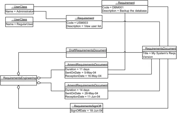
Having a methodology expressed as a class model, software developers can easily instantiate the classes in the method layer in order to create objects in the project layer (Figure 1). For example, an instance of Requirements-Document is needed to represent and track the actual requirements document that is created and maintained in a given project. Similarly, a collection of instances of UserClass will be used to represent the different user classes of the system being constructed. From the process side, an instance of RequirementsEngineering will be created to represent and project manage the activity of performing requirements engineering, and a collection of instances of AmendRequirementsDocument will be created to represent and project manage the successive cycles of amendment to the requirements specification document. Each of these instances will take values for the attributes defined in the class model. For example, each instance of UserClass will have a particular value for Name, and each instance of AmendRequirements-Document will have particular values for the SentOnDate and ReceptionDate attributes (Figure 2). Links between objects in the project layer will be defined from the relationships specified in the method layer; for example, a link between corresponding instances of Requirement and UserClass will be created as an instance of the association between these classes in the methodology that represents the fact that one or more user classes can request a given requirement. As an example involving product and process elements, a link between each instance of Requirement and a specific instance of AmendRequire mentsDocument can be created to reflect the specific amendment cycle that produced that specific requirement (Figure 3).
From the point of view of tools, having a methodology expressed as a class model is also very convenient. Tools used by software developers would implement the class model defined by the methodology and allow users to create instances of them. For example, a project
+Code +Description Requirement +Name UserClass RequirementsEngineering DraftRequirementsDocument +SentOnDate +ReceptionDate AmendRequirementsDocument +SignOffDate RequirementsSignOff 1..* 1..* RequestedBy 1 1 1 0..* 1 1 RequirementsDocument 1 1 Creates 0..* 1 Amends 1 1 SignsOff 1..* 1 Includes 0..1 0..* Produces +Title +Version Document
management and tracking tool would allow a project manager to instantiate Draft RequirementsDocument, AmendRequirementsDocument and other process-related classes to track the progress of the project. Similarly, a modelling tool would allow a software designer to create and maintain instances of the Requirements class and trace each of them to the appropriate instance of Amend-RequirementsDocument created by the project manager. As a conclusion, and from the software developer’s perspective, the method layer must be expressed as a class model from which the appropriate project layer can be created by using conventional instantiation mechanisms.
3.2
The Method Engineer’s Perspective
We have shown in the previous section how expressing a methodology as a class model is appropriate, since it can be used by instantiating the classes in it (which reside in the method layer) to create objects in the project layer. We could argue that, taking a similar approach, the best way of expressing a metamodel is a class model in order that objects in the method layer could be created by instantiation. However, a fallacy lies here. If we gave method engineers a metamodel expressed as a simple class model, they would define methodologies as networks of interconnected objects. But we have established in the previous section that a methodology must be expressed as a class model, not as a network of objects. A metamodel, therefore, should be expressed in such a way that allows a method engineer to derive classes from it and assemble them together into a methodology. The process of generating a methodology in this fashion, by creating a collection of interrelated classes from a given metamodel, involves crossing from the metamodel layer into the method layer. However, this is not achieved though conventional instantiation (as in the case of methodology
enactment) since the resulting entities must be classes rather than objects. Two problems are thus established: first of all, of what kind of entities should a metamodel be composed, so that classes are represented by them? Secondly, what mechanism (other than instantiation) could be used to generate such classes from their representation?
At this point, it is common in the literature to introduce the concept of metaclass as being a class the instances of which are classes themselves. This concept, although often cited by many authors (OMG 2002a , 2003, for example) is self-contradictory and should therefore discarded. If a metaclass actually is a class, then all the characteristics applicable to classes must also be applicable to metaclasses; since the instances of classes are objects , then the instances of metaclasses must be objects too, which contradicts the definition. If a metaclass is, on the contrary, not a class but a different kind of construct, it needs to be properly characterised and described before making any use of it, together with the mechanisms that allow it to be “instantiated” into regular classes. This characterisation is completely avoided by authors using the above-defined concept of metaclass; instead, they just make up an incoherent construct that looks like a class (because it is easy to define it in the well-known terms of name, attributes and relationships) but which generates “instances” perfectly fitted to the authors’ needs without a proper explanation. Such a construct, therefore, cannot be a class, which also contradicts the definition. For all these reasons, we prefer to define metaclass as a regular class that happens to be in the metamodel layer. Since a metaclass is just a class, all characteristics of classes also apply to metaclasses. Actually, the meta- prefix can be often dropped safely since it only denotes the location of the class within the conceptual framework and not any intrinsic property of the class itself.
Name = RegularUser : UserClass Name = Administrator
: UserClass Code = DBM001
Description = Backup the database. : Requirement
Code = USM003 Description = View user list.
: Requirement
: RequirementsEngineering
: DraftRequirementsDocument
Title = My System's Reqs. Version : RequirementsDocument Duration = 11 days SentOnDate = 5-May-04 ReceptionDate = 16-May-04 : AmendRequirementsDocument Duration = 14 days SentOnDate = 28-May-04 ReceptionDate = 11-Jun-04 : AmendRequirementsDocument SignOffDate = 18-Jun-04 : RequirementsSignOff
Once we have discarded the above (standard) concept of metaclass, the answer to our questions (of what kind of entities should a metamodel be constructed so that classes are represented by them, and what mechanism should be used to generate such classes from their representation) comes too easily: the simplest way to represent a class is another class. The subtyping mechanism of conventional object-orientation allows a class to be a more general or more abstract version of another class. Since we need a metamodel that makes a good model of (i.e. represents) any potential methodology that could be derived from it, and a model involves precisely the removal of unnecessary details to keep only the relevant information, expressing the metamodel as a set of abstract classes and using subtyping as the mechanism to cross the conceptual boundary and generate a methodology layer is perfect. On the one hand, it does not introduce strange artefacts such as metaclasses, staying understandable and easy to implement with current technologies; on the other hand, it allows for the generation of concrete classes in the methodology layer from an abstract model, which is exactly what method engineers want. Interestingly, this has parallels with white-box frameworks, which consist of abstract classes from which the software developer creates subclasses for the project in hand.
For example, a method engineer could want to express that each requirements document amendment task modifies a specific requirements specification document. Using the metamodel classes Task and Document as a starting point (Figure 4), the method engineer would create a subtype of Task called AmendRequirementsDocument and a subtype of Document called RequirementsDocument. The method engineer could then link both classes together using an association with the appropriate cardinalities. These classes, part of the generated methodology, form the foundation from which software developers will be able to instantiate actual project-level elements, i.e. specific tasks that amend specific requirements documents.
+Duration Task +SentOnDate +ReceptionDate AmendRequirementsDocument +Title +Version Document RequirementsDocument 0..* 1 Amends
Figure 4. Using abstract classes to represent methodology elements.
We can conclude that expressing metamodels as abstract class models and using subtyping as a generation mechanism is, therefore, a potentially good option.
3.3
Putting It All Together
Expressing metamodels as class models, however, has some interesting consequences. Firstly, the metamodel layer provides type information for the project layer rather than for the method layer. Elements in the project layer are instances of elements in the method layer, which in turn are subtypes of elements in the metamodel layer. From the definition of subtyping, then, elements in the project layer are also instances of elements in the metamodel layer.
Although classes in the metamodel represent classes in the methodology, they do it by subtyping, not by instantiation. This is easy to see by looking at how attributes in metamodel classes are used. Consider an attribute Duration of a class Task in the metamodel (Figure 5). Some classes in the methodology (such as Write MethodCode) would specialise from Task, inheriting Duration. When enacted on a project, instances of WriteMethodCode would take values for Duration. We can see how instances in the project layer are type-conformant with classes in both method and metamodel layers (which makes sense, by definition of subtyping). project method metamodel +Duration Task WriteMethodCode Duration = 3 days : WriteMethodCode «instanceOf»
Figure 5. Representing a metamodel as a class model which can be specialised into the method layer allows attributes and
associations take values in the project layer.
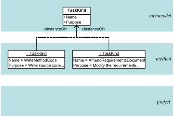
The result of this is that no element in the metamodel layer can provide type information for any element in the method layer, i.e. it is not possible for a methodology element to take values or links for any attributes or relationships, since they are classes and not instances. However, attaching actual data to elements in the methodology layer is useful and even necessary. For example, a method engineer could want to state the purpose of each kind of task that can be potentially performed on a project. Tasks directed at writing code for class methods would have a purpose of “write source code that implements the contract specified by the operation definition”, while tasks for amending requirements specification documents would have a purpose of “mo dify the requirements specification document so that it reflects the accepted change requests submitted by stakeholders”. These properties do not belong to each code writing or requirements document amending task, but to each of these task kinds; all requirements document amending classes have the same purpose, namely “modify the requirements specification document so that it reflects the accepted change requests submitted by stakeholders”. This is a property of a set of potential tasks, i.e. all tasks that aim to amend requirements documents. The method engineer needs a mechanism to give specific values to sets of project layer elements, such as the set of tasks described above. In conventional object-orientation, a set of objects can be mo delled by a class. Thus, a property for which
every object of the set will have a value is easily mo delled as an attribute of that class. Therefore, and continuing with our example, we can say that the metamodel should provide a class representing the different kinds of tasks that can appear in a project, and that class would have an attribute named, in our exa mple, Purpose. Such a class can be named, for example, TaskKind, since there is some semblance to the notion of categorization (e.g. Pirotte et al. 1994, Martin and Odell 1995). Instances of TaskKind will live in the method layer, representing kinds of tasks that can potentially occur in the project layer. For example, the method engineer could create two instances of TaskKind (Figure 6): one, with the name “WriteMethodCode” and purpose “write source code that implements the contract specified by the operation definition”, and another one, named “AmendRequirementsDocument” and with the purpose “modify the requirements specification document so that it reflects the accepted change requests submitted by stakeholders”. project method metamodel +Name +Purpose TaskKind Name = WriteMethodCode Purpose = Write source code...
: TaskKind
Name = AmendRequirementsDocument Purpose = Modify the requirements...
: TaskKind «instanceOf» «instanceOf»
Figure 6. The metamodel must provide some classes that can be used to instantiate objects in the method layer carrying the
appropriate information.
We have established in Section 3.2 that a metamodel is used by a method engineer for creating subclasses of the metamodel classes, and assembling them into a methodology. However, we are saying now that the method engineer can instantiate some classes in the metamodel into objects residing in the method layer. Following our examples so far, a method engineer would create the WriteMethodCode methodology class as a subtype of metamodel class Task, and also the “Write-MethodCode” methodology object as an instance of metamodel class TaskKind. From an intuitive point of view, both methodology elements, class and object, represent the same thing, i.e. tasks that aim to amend a requirements document by incorporating accepted changes. The class version of this concept inherits its attributes and relationships from the Task class in the metamodel and will allow its instances (in the project layer) to take values and links for them. The object version of the concept, on the other hand, takes values and links from the attributes and relationships of its class, namely TaskKind in the metamodel. The Duration attribute in the Task class gets inherited by the WriteMethodCode class and takes specific values for each instance of WriteMethodCode in the project layer. From the object side, we can visualise how
the Purpose attribute of class Task in the metamodel takes the value “write source code that implements the contract specified by the operation definition” in object “Write-MethodCode” in the method layer.
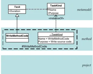
In order to refer to an entity that exhibits both a class facet and an object facet, Pirotte et al. (1994) refer to it as a “two-faceted construct”, whereas Atkinson (1998) or Atkinson and Kühne (2000a) coin the term “clabject”.. This idea of a two-faceted construct or clabject is perfect for our needs, since it nicely models a single concept being modelled simultaneously as a class and as an object. Rather than seeing the WriteMethodCode class and the “WriteMethodCode” object as separate entities in the method layer, we can look at them as a single entity, a clabject, named #WriteMethodCode. As such, #WriteMethodCode will exhibit a class facet (with a name and possibly some attributes and relationships) plus an object facet (with values and links). The class facet of a method-level clabject, as we have explained before, is a subtype of a metamodel class (Task in our example), while the object facet in the same clabject is an instance of a different metamodel class (TaskKind in our example – see Figure 7). method project metamodel WriteMethodCode Name = WriteMethodCode Purpose = Write source code...
: TaskKind +Name +Purpose TaskKind +Duration Task «instanceOf» #WriteMethodCode
Figure 7. A clabject is composed of a class and an object in the method layer that represent the same concept. In this diagram, the
clabject is represented as a labelled dashed rectangle around the component class and object boxes.
It is crucial to understand that these two metamodel classes, the one from which the object facet of a clabject is instantiated and the one from which the class facet of the same clabject is specialised (TaskKind and Task), are different classes, with different sets of attributes and relationships. In our example, TaskKind has attributes Name and Purpose, while Task has attribute Duration. However, it is true that both classes are closely related. In fact, one of them (TaskKind in our exa mple) represents groups of instances of the other (Task in our example); while instances of Task are real tasks, instances of TaskKind are sets of tasks that share some common property (i.e. being of the same kind). In this sense, TaskKind’s instances partition the set of instances of Task. Pirotte et al. (1994) described this in the database literature as “materialization” and, in object technology, Martin and Odell (1992) and Odell (1994) described it as a
“powertype” to denote a type that represents subtypes of another type. Odell’s original definition is not completely appropriate, however, since it states that a powertype P of a type T is a type the instances of which are subtypes of T. Following an argument similar to the one that we used with the concept of metaclass (see Section 3.2), we can see that an instance of a class must be an object, while a subtype of a class is another class. Therefore, they cannot be the same entity, as noted also by Dahchour and Pirotte (2002). The introduction of clabjects comes to the rescue, since we can re -state Odell’s definition and define a powertype P of type T as a type the instances of which are object facets in clabjects of which the class facets are subtypes of T. In our example, TaskKind is a powertype of Task, since instances of TaskKind are the object facets or clabjects of which the class facets are subtypes of Task (Figure 8). The composite entity formed by a type in the metamodel, called the partitioned type (such as Task) plus its powertype (TaskKind in our example) can be called a powertype pattern. The powertype pattern composed of Task and TaskKind can be written as Task/TaskKind or, in short, Task/*Kind. This combination, we note, has strong similarities with the materialization relationship of Pirotte et al. (1994) and Dahchour and Pirotte (2002). In both cases, the two classes, and only these two, belong to the metamodel/conceptual model layer.
method project metamodel +Duration Task WriteMethodCode +Name +Purpose TaskKind Name = WriteMethodCode Purpose = Write source code...
: TaskKind «instanceOf»
#WriteMethodCode
Figure 8. A powertype pattern in the metamodel layer and the clabject generated from it. The relationship between the powertype (TaskKind) and the partitioned type (Task) is indicated here by a dashed line with a bullet end on the side of the
powertype.
From the point of view of tools, clabjects are incredibly powerful and, at the same time, easy to implement. They are powerful because of their dual existence, by virtue of which the object facet can be stored (as any other object) in a database or manipulated by the tool, while the class facet can be used by the tool as a template to create instances. They are easy to implement because they are made of conventional concepts (namely, classes and objects) almost certainly considered by all tool developers and do not require the introduction of new constructs.
Finally, we might note that, although most of the classes in a metamodel will be likely involved in powertype patterns (either as powertypes or partitioned types), some classes
will stand on their own. These classes can be instantiated by a method engineer into objects in the method layer, but they cannot be formally transmitted down to the project layer. These classes, which we call resources González-Pérez and Henderson-Sellers (2005), represent elements in the methodology that are used by software developers without being instantiated, but only as reference or guideline. For example, a notation and a bibliographic re ference about a method element are both method-level entities of value to software developers but do not have object counterparts in the project layer. Method-level entities that are instantiated into project elements (i.e. class facets of clabjects) are called templates González-Pérez and Henderson-Sellers (2005).
3.4
Usage
A powertype-based metamodelling framework is composed of a metamodel layer made of powertype patterns and some stand-alone resource classes. Each powertype pattern, in turn, is composed of a template class (powertype) plus a class representing an element in the project (partitioned type). This is the approach also followed by the Australian Standard AS4651-2004 “Standard Metamodel for Software Development Methodologies” SA (2004).
An example of resource is Notation (with attributes Name and Description), while an example of a powertype pattern is Task/*Kind, in which TaskKind (with attributes Name and Purpose) is the template class and Task (with attribute Duration) represents project elements.
A method engineer would use the metamodel by creating clabjects and objects. Clabjects will be created from powertype patterns, by instantiating the template class into the object facet of the clabject and specialising the project class into the class facet of the same clabject. This combination of instantiation and subtyping is also the essence of the materialization relationship proposed by Pirotte et al. (1994). Objects will be created by regular instantiation of resource classes.
Following our example, Task/*Kind could be instantiated into the #WriteMethodCode clabject, composed of the WriteMethodCode class facet (which inherits attribute Duration from Task) plus the “WriteMethodCode” object facet (which takes values Name = “WriteMethodCode” and Purpose = “write source code that implements the contract specified by the operation definition” from TaskKind). Also, resource class Notation could be instantiated into object “UML”, with values Name = “UML” and some appropriate text for Description (Figure 9).
A software developer would use the methodology by creating objects from the class facets of clabjects and by referring to the object facets of clabjects and to resource objects for additional information.
In the example shown in Figure 9, the class Write-MethodCode (class facet of the corresponding clabject) is instantiated into object WMC1 (which takes value Duration = 2.5 hours). Also, the object “WriteMethod-Code” (the object facet of the same clabject) can be
consulted for guidance. Finally, the object “UML” can also be consulted as necessary when using that notation.
method project metamodel #WriteMethodCode +Duration Task WriteMethodCode +Name +Purpose TaskKind Name = WriteMethodCode Purpose = Write source code...
: TaskKind «instanceOf» Duration = 2.5 hours WMC1 : WriteMethodCode «instanceOf» +Name +Description Notation Name = UML Description = The Unified...
: Notation «instanceOf»
Figure 9. Example of the interactions between metamodel, method and project layers. Powertype patterns (Task/*Kind) and
clabjects (#WriteMethodCode) are shown, as well as a resource element (object with Name = “UML”) and a project-level
element (object named WMC1).
4
Other Approaches
4.1
The Strict Metamodelling Paradigm
Most of the current metamodelling alternatives use a similar approach, often called the “strict metamodelling paradigm”: elements in any of the layers must be instances of elements in the layer immediately above, bar the top one, which is often described as “self-referencing”, i.e. it is an instance of itself. The metamodels of UML OMG (2003), SPEM OMG (2002b) and OPEN Firesmith and Henderson-Sellers (2002) use this conceptualization, and Atkinson and Kühne explic itly advocate it in Atkinson and Kühne (2000b, 2002, 2003). Although these share a layered architecture with our approach, the self-imposed need of having only “instance-of” relationships crossing layer boundaries make them of dubious utility in real-world situations in which round-trip modelling (from the metamodel to the project and back) and comprehensive tool usage are present. In our view, this self-imposed limitation, although commonly accepted unchallenged, has its origins in a poor interpretation of the concept of “representation”. Since the mid 1980s, when the ANSI X3.138 “Information Resource Dictionary System” standard ANSI (1989) was developed, each layer in a metamodelling architecture was defined as a representation of the layer immediately below. The concept of representation admits many implementations (through instantiation, specialisation, interface realisation, etc.), but most existing metamodelling approaches have chosen to equate it with instantiation (see e.g. discussion in Pirotte et al. (1994)), an approach that has become an unchallenged standard in OO modelling. The benefits of considering other means of representation, such as specialisation, are well demo nstrated in this paper. Only two reasons come to mind why restricting the interactions between layers to strict “instance-of” relationships could be acceptable. On the one hand, it is easier and quicker to implement tools that are based on a simplistic interaction model. However, if our motivations go beyond selling tools as quickly as possible, we should
look for more rigorous approaches. On the other hand, once a large and inflexible standards body such as the OMG has adopted a given approach, many authors find it easier to follow it unquestioningly, even if it is flawed, than to try to fix it.
Looking into the specific problems of the strict metamo delling paradigm, the major issue is the following. Metamodels are given as class mo dels (see UML, SPEM or OPEN, for exa mple), and methodologies are supposedly constructed from them by method engineers through instantiation of metamodel classes. Once methodologies are constructed, they are used by software developers by, again, instantiating classes in the methodology into objects in the project. This poses a contradiction: methodologies must be composed of classes (so software developers can instantiate them into project objects), but the result of instantiating a metamodel is a collection of objects, not classes. Where do the classes come from? Most of the metamodelling standards and guides reviewed by us make no mention of this, simply assuming that objects will turn into classes magically. Neither are the implications of this, especially with regard to attributes and associations, explored.
In addition, the strict metamodelling paradigm advocates metamodels that only represent the method layer, saying nothing about the project layer. Following their approach, there is no way in which a metamodel can exert control on how the project layer will be organised. In a powertype-based metamodelling approach, partitioned types represent entities in the project layer, while powertypes represent entities in the method layer. This is called dual representation. Characteristics of both method and project elements can be defined in the metamodel and transmitted down the specialisation and instantiation hierarchies, thus achieving a degree of control over both method and project that cannot be obtained using strict metamodelling alternatives.
The strict metamodelling paradigm, in this light, reflects a desire for a simple world. Unfortunately, the real world is not that simple. The strict metamodelling paradigm offers an oversimplified solution that cannot cope with the real needs of the real world.
4.2
Potency and Deep Instantiation
As an alternative to the problem derived from the strict metamodelling approach for software development approaches (outlined in Section 4.1), Atkinson and Kühne have proposed the concepts of potency and deep instantiation as a means to transmit features (attributes and relationships) beyond a simple level in a specialisation hierarchy Atkinson and Kühne (2001). In this, traditional OO instantiation is seen as a special case (to be called shallow instantiation) of a more generic mechanism called deep instantiation, which operates between clabjects rather than between classes and objects. When a clabject is created by instantiation from another clabject, potency determines how features are transmitted. For features with potency > 0, a feature is created in the instance with its potency decremented by 1. When the potency of a feature becomes zero, we have a “value”, i.e. a slot in the case of attributes and a link in the case of associations. This
contrasts to the traditional OO approach, in which a feature of a class is “converted” into a value of an object whenever the class is instantiated. For example, consider a class Task with an attribute Duration. Usually, instances of Task will be objects with a specific value for Duration. Using deep instantiation, we could assign a potency of 2 to Duration, so instances of Task will actually “inherit” the Duration attribute as is, not getting a value. Such instances of tasks would be clabjects, in which the potency of Duration would be decremented to 1. Instances of these instances would take values for Duration, since its potency would reach zero.
The results of applying deep instantiation can be shown to be equivalent to those from powertype metamodelling as described here. The difference is that, in deep instantiation, a single class is present in the metamodel layer for each conceptual entity in the modelling domain. While this could be regarded as simpler than the dual classes of both powertyping and materialization, this duality permits more explicit (and arguably more understandable) modelling of a class and its categorization characteristics.
5
Conclusions
This paper has presented the rationale behind powertype-based metamodelling and shown how this approach emerges naturally when metamodelling is considered in its entirety and within its intended usage framework. The perspectives of software developers (users of methodologies) and method engineers (users of metamodels and creators of methodologies) are different, and both must be supported. Both communities manage different concepts that are, nevertheless, closely related. Powertype-based metamodelling (and also the materialization relationship) acknowledges this fact by making use of pairs of classes to model method-level concepts (such as TaskKind) and project-level concepts (such as Task). It has been shown how each of these pairs composes a powertype pattern that ties together both concepts and, at the same time, allows for independent usage. A metamodel mainly defined as a collection of powertype patterns, such as the Standard Metamodel for Software Development Methodologies SA (2004), is used by method engineers creating clabjects in the method layer, each clabject being a derivation of a given powertype pattern. The class and object facets of the clabject represent the same concepts for different communities and usages: the class facet, a subtype of the partitioned type in the powertype pattern, is useful for the software developer to instantiate project-level objects from, while the object facet, an instance of the powertype in the powertype pattern, is useful for the method engineer (and associated tools) to characterise the methodology as necessary. Characteristics of other alternatives have also been discussed, showing how the flexibility and degree of control provided by a powertype-based approach cannot be matched by these other methods.
6
Acknowledgements
The authors wish to thank the Australian Research Council (grant numbers DP0211675 and DP0451213) for financial support for this work. This is Contribution number 04/29
of the Centre for Object Technology Applications and Research.
7
References
ANSI (1989): Information Resource Dictionary System, X3.138, American National Standards Institute. Atkinson, C. (1998): Supporting and applying the UML
conceptual framework. In «UML» 1998: Beyond the Notation, Vol. 1618. BÉZIVIN, J. and MULLER, P.-A. (eds). Springer-Verlag, Berlin, 21-36.
Atkinson, C. and Kühne, T. (2000a): Meta-level independent modelling. In International Workshop on Model Engineering at 14th European Conference on Object-Oriented Programming.
Atkinson, C. and Kühne, T. (2000b): Strict profiles: why and how. In «UML» 2000: Advancing the Standard, Vol. 1939. EVANS, A., KENT, S. and SELIC, B. (eds). Springer-Verlag, Berlin, 309-322.
Atkinson, C. and Kühne, T. (2001): The essence of multilevel metamodelling. In «UML» 2001: Modeling Languages, Concepts and Tools, Vol. 2185. GOGOLLA , M. and KOBRYN, C. (eds). Springer-Verlag, Berlin, 19-33.
Atkinson, C. and Kühne, T. (2002): Rearchitecting the UML infrastructure. ACM Transactions on Modeling and Computer Simulation, 12(4). 290-321
Atkinson, C. and Kühne, T. (2003): Model-driven development: a metamodeling foundation. IEEE Software,20(5), 36-41.
Bandinelli, S., Fuggetta, A., Lavazza, L., Loi, M. and Picco, G. P. (1993): Modeling and Improving an Industrial Software Process. IEEE Transactions on Software Engineering,21(5): 440-453. Dahchour, M. and Pirotte, A. (2002): Materialization and
its metaclass implementation. IEEE Transactions on Knowledge and Data Engineering, 14(5): 1078-1094.
Firesmith, D.G. and Henderson-Sellers, B. (2002): The OPEN Process Framework. London, Addison- Wesley
Gershenson, C. (2002): Complex philosophy. Procs. First Biennial Seminar on the Philosophical, Methodological & Epistemological Implications of Complexity Theory. La Habana, Cuba
González-Pérez, C.A. and Henderson-Sellers, B. (2005): Templates and resources in software development methodologies. Journal of Object Technology,[in press, May/June 2005 issue]. Graham, I. (1995): A non-procedural process model for
object-oriented software development. Report on Object Analysis and Design,1(5): 10-11. Kleppe, A., Warmer, J. and Bast, W. (2003): MDA
Explained: The Model Driven Architecture - Practice and Promise. Reading, MA,Addison- Wesley.
Martin, J. and Odell, J.J. (1992): Object-Oriented Analysis and Design. Englewood Cliffs, NJ., Prentice- Hall.
Martin, J. and Odell, J.J. (1995): Object-Oriented Methods: A Foundation. Englewood Cliffs, NJ., Prentice- Hall.
Odell, J.J. (1994): Power types. Journal of Object- Oriented Programming,7(2): 8-12.
OMG (2002a): Meta Object Facility (MOF) Specification, formal/2002-04-03, Object Management Group. OMG (2002b): Software Process Engineering Metamodel
Specification, formal/2002-11-14, Object Management Group.
OMG (2003): Unified Modelling Language Specification, formal/03-03-01, Object Management Group. Pirotte, A., Zimányi, E., Massart, D. and Yakusheva, T.
(1994): Materialization: a powerful and ubiquitous abstraction pattern. In 20th International Conference on Very Large Data Bases. BOCCA, J., JARKE, M. and ZANIOLO, C. (eds). 630-641.
Podnar, I., Mikac, B. and Caric, A. (2000): SDL based approach to software process modeling. In EWSPT 2000. CONRADI, R. (ed). Berlin, Springer-Verlag.
Rolland, C., Prakash, N. and Benjamen, A. (1999): A multi-model v iew of process modelling. Requirements Engineering Journal, 4(4): 169-187.
SA (2004): Standard Metamodel for Software Development Methodologies, AS 4651-2004, Standards Australia.
Seidewitz, E. (2003): What models mean. IEEE Software, 20(5): 26-31.
Störrle, H. (2001): Describing process p atterns with UML. In Software Process Technology, Vol. LNCS 2077, Berlin, Springer-Verlag, 173-181.