Sensor Discovery and Configuration Framework for
The Internet of Things Paradigm
Charith Perera, Prem Prakash Jayaraman,
Arkady Zaslavsky, Dimitrios Georgakopoulos
CSIRO Computational Informatics, Canberra, ACT 2601, Australia {charith.perera, prem.jayaraman, arkady.zaslavsky,
dimitrios.georgakopoulos}@csiro.au
Peter Christen
Research School of Computer Science, The Australian National University,
Canberra, ACT 0200, Australia [email protected]
Abstract—Internet of Things (IoT) will comprise billions of devices that can sense, communicate, compute and potentially actuate. The data generated by the Internet of Things are valuable and have the potential to drive innovative and novel applications. The data streams coming from these devices will challenge the traditional approaches to data management and contribute to the emerging paradigm of big data. One of the most challenging tasks before collecting and processing data from these devices (e.g. sensors) is discovering and configuring the sensors and the associated data streams. In this paper, we propose a tool called SmartLink that can be used to discover and configure sensors. Specifically,SmartLink, is capable of discovering sensors deployed in a particular location despite their heterogeneity (e.g. different communication protocols, communication sequences, capabili-ties).SmartLinkestablishes the direct communication between the sensor hardware and cloud-based IoT middleware. We address the challenge of heterogeneity using a plugin architecture. Our prototype tool is developed on the Android platform. We evaluate the significance of our approach by discovering and configuring 52 different types of Libelium sensors.
I. INTRODUCTION
The Internet of Things (IoT) received its first attention in late 20th century. The term was coined in 1998 [1] and later defined as “The Internet of Things allows people and
things1to be connected Anytime, Anyplace, with Anything and
Anyone, ideally using Any path/ network and Any service”[8].
As highlighted in the definition, connectivity among devices is a critical functionality that is required to fulfil the vision of the IoT. The following statistics highlight the magnitude of the challenge we need to address in the future and motivate our research. Due to increasing popularity of mobile phones over the past decade, it is estimated that there about 1.5 billion Internet-enabled PCs and over 1 billion Internet-enabled mobile phones today. The number of things connected to the Internet has exceeded the number of people on earth in 2008. By 2020, there will be 50 to 100 billion devices connected to the Internet [22]. Similarly, according to BCC Research [2], the global market for sensors was around $56.3 billion in 2010. In 2011, it has risen to around $62.8 billion. Global market for sensors is expected to increase to $91.5 billion by 2016, at a compound annual growth rate (CAGR) of 7.8%.
Sensing as a service [19] has also gained popularity among academia and industry. It envisions to offer sensing capability 1We use terms, ‘objects’ and ‘things’ interchangeably to give the same
meaning as they are frequently used in the IoT related documentation. Other terms used by the research community are ‘smart objects’, ‘devices’, ‘nodes’.
as a service similar to other offerings such as infrastructure as a service (IaaS), platform as a service (PaaS), and software as a service (SaaS). In such environment, discovering, connecting and configuring sensors2 is critical so cloud-based IoT plat-forms can retrieve data from sensors. The sensing as a service paradigm and the importance of sensor configuration is further discussed in [19]. This work is also motivated by our previous work which focused on utilising mobile phones and similar capacity devices to collect sensor data. In DAM4GSN [20], we proposed an application that can be used to collect data from sensors built-in to mobile phones. Later, we proposed MoSHub [15] that allows a variety of different external sensors to be connected to a mobile phone using an extensible plugin architecture. MoSHub also configures the cloud middleware accordingly. In MOSDEN [16], we developed a complete middleware for resource constrained mobile devices that is capable of collecting data from both internal and external sensors. MOSDEN can also apply SQL-based fusing on data streams in real-time. As we mentioned earlier, in order to collect data from sensors, first we need to discover and configure the available sensors in such a way a that cloud can
communicate with them. In our previous work, discovery and
configuration steps are performed manually. In this work, we propose an approach that can be used to discover and configure sensors autonomously.
II. RESEARCHCHALLENGES
Asensor configuration processdetects, identifies, and con-figures sensor hardware and cloud-based IoT platforms in such a way that software platforms can retrieve data from sensors when required. In this section, we identify the importance of sensor configuration, several major challenges and factors that need to be considered. The process of sensor configuration in the IoT is important due to two main reasons. Firstly, it establishes the connectivity between sensor hardware and software systems which allows to retrieve data from sensor. Secondly, it allows to optimize the sensing and data commu-nication by considering several factors as discussed below. Let us consider the following problem‘Why is sensor configuration
a challenging task in the IoT environment?’. The major factors
that makes sensor configuration challenging are1) the number of sensors, 2) heterogeneity, 3) scheduling, sampling rate,
2Each device may comprise one or more sensors. Such device can also be
called assensor node. In this work, we configure the entire sensor node. Charith Perera, Prem Prakash Jayaraman, Arkady Zaslavsky, Peter Christen, and Dimitrios Georgakopoulos, Sensor Discovery and
Configuration Framework for the Internet of Things Paradigm, Proceedings of the IEEE World Forum on Internet of Things (WF-IoT),
communication frequency, 4) data acquisition, 5) dynamicity,
and6) context[18].
1) Number of Sensors: When the number of sensors that
need to be configured is limited, we can use manually or semi-autonomous techniques. However, as the numbers grow rapidly towards millions and billions, such methods become extremely inefficient, expensive, labour-intensive, and in most situations impossible. Therefore, large numbers have made sensor configuration challenging. An ideal sensor configuration approach should be able to configure sensors autonomously as well as within very short periods of time.
2) Heterogeneity: This factor can be interpreted in different
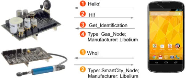
perspectives. Firstly, heterogeneity in term of communication technologies used by the sensors as presented in Table I. Secondly, the heterogeneity in term of measurement capabil-ities (e.g. temperature, humidity, motion, pressure). Thirdly, the types of data (e.g. numerical (small in size), audio, video (large in size)) generated by sensors are also heterogeneous. Finally, the communication sequences, as depicted in Figure 1, and security mechanisms used by different sensors, are also heterogeneous (e.g. exact messages and sequence need to be followed to successfully communicate with a given sen-sor). These differences make the sensor configuration process challenging. An ideal sensor configuration approach that is designed for the IoT paradigm should be able to handle such heterogeneity. Towards this, the proposed solution should be scalable and should provide support for new sensors as they come to the market.
Hello! 1 Who! 1 Hi! 2 Type: SmartCity_Node; Manufacturer: Libelium 2 3 Get_Identification 4 Type: Gas_Node; Manufacturer: Libelium
Fig. 1: Heterogeneity in term of communication and mes-sage/command passing sequences. Some sensors may need only a few message/command passes and others may require more. The messages/commands understood by each sensors may also vary.
TABLE I: Wireless Technology Comparison ZigBee GPRS-GSM WiFi Bluetooth Standard 802.15.4 802.11b 802.15.1 System Resources 4-32KB 16MB+ 1MB+ 250KM+ Batterylife (days) 100-1000+ 1-7 0.5-5 1-7 Network Size 264 1 32 7 Bandwidth (KB/s) 20-250 64-128+ 11000 720 Transmission Range (meters) 1-100+ 1000 1-100 1-10+
Success Metrics Reliability, Power, Cost Reach, Quality Speed, Flexibility Convenience, Cost
3) Scheduling, Sampling Rate, and Network
Communi-cation: Sampling rate defines in which frequency sensors
need to generate data (i.e. sense the phenomenon) (e.g. sense temperature every 10 seconds). Deciding an ideal (e.g. balance between user requirement and energy consumption) sampling
rate can be a very complex task that has a strong relationship with 6) Context. Schedule defines the time table of sensing and data transmitting (e.g. sense temperature only between 8am to 5pm weekdays). Network communication defines the frequency of data transmission (e.g. send data to the cloud-based IoT platform every 60 seconds). Designing efficient sampling and scheduling strategies and configuring sensors accordingly is challenging.
4) Data Acquisition:This can be divided into two categories:
based on responsibility and frequency [18]. There are two methods that can be used to acquire data from a sensor based on responsibility: push (e.g. cloud requests data from a sensor and the sensor responds with data) and pull (e.g. sensor pushes data to a cloud without explicit cloud request). Further, based on frequency, there are two data acquisition methods: instant (e.g. send data to the cloud when a predefined event occurs) and interval (e.g. periodically send data to the cloud). Pros, cons, and applicabilities are discussed in [18]. Using appropriate data acquisition methods based on the context information is essential to ensure the efficiency.
5) Dynamicity: This means the frequency of changing
po-sitions / appearing / disappearing of the sensors at a given location. IoT envisions that most of the objects we use in everyday lives will have sensors attached to them. Ideally, we need to connect and configure these sensors to software plat-forms in order to analyse data and understand the environment better. We observed several domains and broadly identified different levels of dynamicity based on mobility3.High level: sensors move/ appear/ disappear at a higher frequency (e.g. RFID and other low-level, low-quality, less reliable, cheap sensors. Such sensors will be attached to consumables such as stationary, food packaging, etc.).Low level:sensors embedded and fitted into permanent structures (such as buildings and air condition systems) can be categorized under this level. An ideal sensor configuration platform should be able to efficiently and continuously discover and re-configure sensors in order to cope up with high dynamicity.
6) Context:Context information plays a critical role in sensor configuration in the IoT. The objective of collecting sensor data is to understand the environment better by fusing and reasoning them. In order to accomplish this task, sensor data need to be collected in timely and location sensitive manner. Each sensor needs to be configured by considering context information. Let us consider a scenarios related to smart agriculture to understand why context matters in sensor configuration. Se-vere frosts and heat events can have a devastating affect on crops. Flowering time is critical for cereal crops and a frost event could damage the flowering mechanism of the plant. However, ideal sampling rate could be varied depending on both season of the year as well as the time of the day. For example, a higher sampling rate is necessary during the winter season and night time. In contrast, lower sampling would be sufficient during summer and day time. On the other hand, some reasoning approaches may required multiple sensor data reading. For example, a frost event can be detected by fusing air temperature, soil temperature, and humidity. However, if an
3It is important to note that same object can be classified into different
levels depending on the environment they belongs to. Further, there is no clear definition to classify objects into different levels of dynamicity. However, our categorization allows to understand the differences in dynamicity.
air temperature sensor stopped sensing due to malfunctioning, there is no value in sensing humidity, because frost events cannot be detected without temperature. Therefore, configuring the humidity sensor to sleep is ideal until the temperature
sensor starts sensing again. Such approaches save energy by
eliminating unnecessary sensing and communication.
III. ARCHITECTURALDESIGN
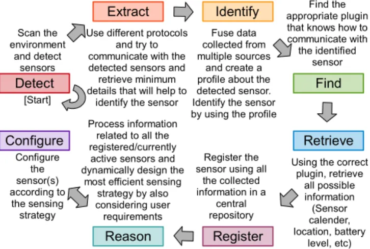
Previously, we identified several major factors that need to be considered when developing an ideal sensor configu-ration model for the IoT. This section presents the detailed explanation of our proposed solution: Context-aware Dynamic Discovery of Things (CADDOT). Figure 2 describes the main phases of the proposed model.
Phases in CADDOT model:The proposed model consists of
eight (8) phases:detect, extract, identify, find, retrieve, register,
reason, and configure. Some of the tasks mentioned in the
model are performed by the SmartLink tool and other tasks are performed by cloud-based IoT middleware.
Scan the environment and detect sensors Detect Identify Find Retrieve Register Extract Reason Configure
Use different protocols and try to communicate with the detected sensors and retrieve minimum details that will help to
identify the sensor
Fuse data collected from multiple sources
and create a profile about the detected sensor. Identify the sensor by using the profile
Find the appropriate plugin that knows how to communicate with the identified
sensor
Using the correct plugin, retrieve all possible information (Sensor calender, location, battery level, etc) Register the
sensor using all the collected information in a central repository Configure the sensor(s) according to the sensing strategy Process information related to all the registered/currently
active sensors and dynamically design the
most efficient sensing strategy by also considering user
requirements [Start]
Fig. 2: CADDOT Model for Sensor Configuration 1) Detect: Sensors are configured to actively seek a wireless access points (WiFi or Bluetooth) which they can be connected to without any authorization, because at this point sensors do not have authentication details. Sensors will get them inphase
(8). SmartLink becomes an open wireless hotspot so sensors
can connected to it in an ad-hoc manner.
2) Extract:In this phase,SmartLinkextracts information from the sensor detected in the previous phase. Each sensor may be designed to respond to a different message-passing sequence depending on the sensor manufacturer and the sensor program developer. Even though the sensors and theSmartLinkmay use the same communication technology/ protocol (e.g. TCP, UDP, Bluetooth), the exact communication sequence can be varied from one sensor to another. Therefore, it is hard to find the specific message passing sequence that each sensor follows. To address this challenge, we propose every sensor to respond to a common message during the communication initiation process. For example,SmartLinkbroadcasts a message [WHO] where the sensors are expected to respond by providing a minimum amount of information about themselves, such as sensor unique identification number, model number / name, and manufacturer. This is similar to the TEDS mechanism discussed in [9]. It is important to note that we propose this
[WHO] constraint only for minimum information extraction. Once the sensor is identified, subsequent communications and heterogeneity of message-passing sequences is handled by matching plugins.
3) Identify:SmartLinksends all the information related to the newly detected sensor to the cloud. Cloud-based IoT middel-ware queries and reasons its data stores using the information. This process identifies the complete profile of the sensor. 4) Find: Once the cloud identifies the sensor uniquely, this information is used to find a matching plugin (can also be called driver) which knows how to communicate with a compatible sensor in full capacity. The IoT middleware pushes the plugin toSmartLink where it gets installed4.
5) Retrieve:Now,SmartLinkknows how to communicate with the detected sensor at full capacity with the help of the newly downloaded plugin. Next, SmartLink retrieves the complete set of information that the sensor can provide (e.g. configura-tion details such as schedules, sampling rates, data structures /types generated by the sensor, etc.). Further, SmartLink may communicate with other available sources (e.g. databases, web services) to retrieve additional information related to a sensor. 6) Register:Once all the information about a given sensor has been collected, registration takes place in the cloud. The sensor descriptions are modelled according to the semantic sensor network ontology (SSNO) [17]. This allows semantic querying and reasoning. Some of the performance evaluation related to the SSN ontology and semantic querying are presented in [17]. 7) Reason: This phase plays a significant role in the sensor configuration process. It designs an efficient sensing strategy. Reasoning takes place in a distributed manner. The cloud IoT middleware retrieves data from sensors and other devices and identifies their availabilities and capabilities. Further, it con-siders the context information in order to design an optimized strategy. However, the technical details related to this reasoning process is out of the scope of this paper. At the end of this phase, a comprehensive plan (e.g. schedule and sampling rate) for each individual sensor is designed.
8) Configure: Sensors and cloud-based IoT software systems are configured based on the strategy designed in the previous phase. Schedules, communication frequency, and sampling rates that are custom designed for each sensor are pushed into the individual sensors. The connection between the sensor and the IoT software system are established through direct wireless communication or through intermediate devices such as MOSDEN [16] so the cloud can retrieve data from sensors. The details (IP address, port, authentication, etc.) required to accomplish above task is also provided to the sensor.
IV. DESIGNDECISIONS ANDAPPLICATIONS
We made a number of design decisions during the devel-opment of the CADDOT model. These decisions address the challenges we highlighted in earlier sections.
Security Concerns and Application Strategies:There are
different ways to employ our proposed model CADDOT as 4In practice, IoT middleware sends a request toGoogle Play store. Google
store pushes the plugin (i.e. an android application) to the SmartLink au-tonomously via the Internet.
Sensor Node
Sensor Node (a) Raspberry Pi (as SmartLink) (b) Mobile Phone
(as SmartLink) Human Robot
Communication Related to Configuration Sensor Data Transmission
Fig. 3: Application strategies of CADDOT model and
SmartLink tool. (a) usage of static SmartLink (b) usage of
mobileSmartLink.
well as the tool SmartLinkin real world deployments. Figure 3 illustrates two different application strategies. It is important to note that neither our model nor the software tool is limited to a specific device or platform. In this paper, we conduct the experimentations on an Android-based mobile phone, as detailed in Section V. In strategy (a), a Raspberry Pi (raspber-rypi.org) is acting as theSmartLinktool. This strategy is mostly suitable for smart home and office environments where WiFi is available. Raspberry Pi continuously performs the discovery and configuration process, as explained in Section III. Finally, Raspberry Pi provides the authentication details to the sensor which is to connected to the secure home/office WiFi network. The sensor is expect to send data to the processing server (local or on cloud) directly over the secured WiFi network. In this strategy, SmartLink is in static mode. Therefore, several
SmartLink instances installed on Raspberry Pi devices may be
required to cover a building. However, this strategy can handle a high level of dynamicity.
The strategy (b) is more suitable for situations where WiFi is not available or less dynamic. Smart agriculture can be considered as an example. In this scenario, sensors are deployed over a large geographical area (e.g. Phenonet: phenonet.com). Mobile robots (tractors or similar vehicles) with aSmartLinktool attached to them can be used to discover and configure sensors. SmartLink can then help to establish the communication between sensors and sinks. The permanent sinks used in the agricultural fields are usually low-level sinks (such as Meshlium [13]). Such sinks cannot perform sensor discovery or configuration in comparison to SmartLink. Such sinks are designed to collect data from sensors and upload to the cloud via 3G.
Other strategies can be built by incorporating the different characteristics pointed out in the above two strategies. This shows the extensibility of our solution. For example, Raspberry Pi, which we suggested for use as a SmartLink in strategy (a), can be replaced by corporate mobile phones. So, without bothering the owner, the corporate mobile phones can silently perform the work of a SmartLink.
System Architecture: The CADDOT model consists
of three main components: sensors, a mobile device (i.e.
SmartLink), and the cloud middleware. All three components
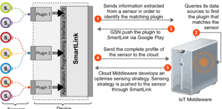
need to work collectively in order to perform sensor discov-ery and configuration successfully. Figure 4 illustrates the interactions between the three components. The phases we explained earlier relating to the CADDOT model in Figure 2 can be seen in Figure 4 as well. As we mentioned before,
SmartLinkis based on plugin architecture. The coreSmartLink
application cannot directly communicate with a given sensor. A plugin needs to act as a mediator between the sensor and
the SmartLink core application, as illustrated in Figure 4.
S1 S2 S7 S3 S4 S5 S6 Plugin 1 Plugin 2 A p p lic a tio n P ro gr a m m in g In te rf a ce ( A P I) Sensors Device Plugin 3 S m ar tL in k IoT Middleware 1
Sends information extracted from a sensor in order to identify the matching plugin
Queries its data sources to find the plugin that matches the sensor GSN push the plugin to
SmartLink via Google Play 2
3
4
Send the complete profile of the sensor to the cloud
Cloud Middleware develops an optimise sensing strategy. Sensing
strategy is pushed to the sensor through SmartLink
5
Fig. 4: System architecture of the CADDOT model which con-sists of three main components: sensors, SmartLink tool, and the cloud middleware. Order of the interactions are numbered.
The task of the mediator is to translate the commands back and forth. This means that in order to configure a specific sensor, the SmartLink core application needs to employ a plugin that is compatible with both the SmartLinkapplication itself and the given sensor. The sensors can be programmed in different ways. We do not restrict the developers to one single sensor-level program design. In order to allow SmartLink to communicate with a sensor which runs different program designs, developers need to develop a plugin that performs the command translations. Plugin designing is guided by an AIDL interface which explains the mandatory functionalities that needs to be implemented.
V. IMPLEMENTATION
Hardware Setup: We employed the Global Sensor Network
(GSN) [7] middleware as the cloud IoT platform and hosted it on a laptop with Intel Core i5 CPU and 4GB RAM during the proof of concept validation. However, our CADDOT model can accommodate any other IoT middleware as well. We de-ployed theSmartLink application in a Google Nexus 4 mobile phone (Qualcomm Snapdrago S4 Pro CPU and 2 GB RAM), which runs Android platform 4.2.2 (Jelly Bean). We deployed 52 sensors in the third floor of the CSIT building (#108) at the Australian National University. All sensors we employed in our experiments are manufactured by Libelium (libelium.com). The sensors senses wide variety of environment phenomenon, such as temperature, motion, stretch, humidity, presence and so on. SmartLinksupports sensor discovery and configuration using both WiFi and Bluetooth. Other communication tech-nologies such as ZigBee and RFID are supported through Libelium Expansion Radio Boards.
Software Setup: GSN [7] is developed in Java. We
ex-tended GSN using the techniques proposed in [15], so it can configure it self accordingly. The Android platform has been used to develop the SmartLink application. Further, we employed the plug-in architecture called Android Interface Definition Language (AIDL) provided to facilitate plug and play functionality. AIDL allows SmartLink to communicate with sensors effective and efficient manner. In order to simulate the heterogeneity of the sensors (in term of communica-tion sequences), we programmed each sensor to behave and respond differently. As a result, each sensor can only be communicated by using a plug-in that supports the same communication sequence. Figure 5 shows how the interaction
Sensor replies with basic details ['WASP_SmartCity015']
SmartLink sends['WHO']message to the sensor
Connection establishes when a sensor finds a SmartLink
S m ar tL in k C lo u d
Continuously searching for SmartLink
P lu g in f o r se n s o r W A S P _ S m ar tC it y0 15 S e ns or Communicates with the server and identifies the matching plugin
Asks for complete sensor profile [Data types and units, current configuration]
Sensor replies with full sensor profile
Configures sampling rate Configures communication frequency
Configures sensing schedule and data acquisition method Configures network configuration
[IP, Port, Authentication]
Sensor connects to the cloud [via a secure network]
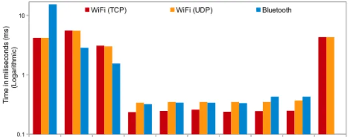
Fig. 5: Sequence diagram demonstrates the interaction between a sensor and theSmartLinktool. However, interaction sequence may varied depend on how the sensor is programmed. between sensor and the SmartLink application occurs. We measure the average amount of time taken by each step (average of 30 sensor configurations). Figure 6 illustrates the results and the following steps are considered: Time taken to (1) set up the sensor, (2) initiate connection between the sensor
andSmartLink, (3) initiate communication between sensor and
SmartLink, (4) extract sensor identification information, (5)
retrieve the complete profile of the sensor, (6) configure the sampling rate, (7) configure the communication frequency, (8) configure the sensing schedule, (9) configure the network and authentication details (so the sensor can directly connect to the cloud), (10) connect to the secure network using the provided authentication details.
VI. EVALUATION
According to Figure 6, the actual configuration tasks take less that one second. There is a slight variation in completion time in configuration steps (4) to (9). This is due to storage access and differences in configuration command processing. Despite the protocol we use, sensors takes 5 to 15 seconds to boot and set-up themselves self. The setup stage consists of activities such as reading default configuration from storage, switch-on necessary modules and components (communication modules, real-time clock, SD card, sensor broads and so on). According to the results, it is evident that a single sensor can be configured in less than 12 seconds (i.e. assuming sensors are already booted, which takes additional 5 to 15 seconds depend-ing on the communication protocol). Additionally, SmartLink
can configure multiple sensors at given time in parallel. This is a significant improvement over a manual labour intensive sensor configuration approaches.
(1) (2) (3) (4) (5) (6) (7) (8) (9) (10)
0.1 1
10 WiFi (TCP) WiFi (UDP) Bluetooth
T im e in m ili se co nd s (m s) (L o g a ri th m ic )
Fig. 6: Time taken to configure a sensor in step-by-step. Experiments are conducted using TCP, UDP, and Bluetooth.
VII. RELATEDWORK
In this section, we review some of the state-of-the-art solutions developed by in academia, as well as commercial business entities. Our review covers both mature and immature solutions proposed by start-up initiatives as well as large-scale projects. The proposed CADDOT model as well as the
SmartLink tool help to overcome some of the weaknesses in
existing solutions.
There are commercial solutions available in the market that have been developed by start-up IoT companies [21] and the research divisions of leading corporations. These solutions are either still under development or have completed only limited deployments in specialized environments (e.g. demos). We discuss some of the selected solutions based on their pop-ularity. Ninja Blocks(ninjablocks.com), Smart-Things (smart-things.com), andTwine(supermechanical.com) are commercial products that aim at building smart environments [21]. They use their own standards and protocols (open or closed) to com-municate between their own software systems and sensor hard-ware components. The hardhard-ware sensors they use in their solu-tions can only be discovered by their own software systems. In contrast, our pluggable architecture can accommodate virtually any sensor. Further, our proposed model facilitates different domains (e.g. indoor, outdoor) using different communication protocols and sequences. In addition, the CADDOT model can facilitate very high dynamicity and mobility. HomeOS
[5] is a home automation operating system that simplifies the process of connecting devices together. Similar to our plugin architecture, HomeOS is based on applications and drivers which are expected to be distributed via an on-line store called
HomeStorein the future. However,HomeOSdoes not perform
additional configuration tasks (e.g. scheduling, sampling rate, communication frequency) depending on the user requirements and context information. Further, our objective is to develop a model that can accommodate a wider range of domains by providing multiple alternative mechanisms, as discussed in section IV. Hu et al. [9] have proposed a sensor configuration mechanism that uses the information stored in TEDS [10] and SensorML [3] specifications. Due to the unavailability and unpopularity of TEDS among sensor manufacturers, we use TEDS-like mechanism, by establishing a standard communi-cation message formats, to extract information from a give sensors in phase 2of the CADDOT model.
Actinium [12] is a RESTful runtime container that provides Web-like scripting for low-end devices through a cloud. It en-capsulates a given sensor device using a container that handles the communication between the sensor device and the software system by offering a set of standard interfaces for sensor configuration and life-cycle management. The Constrained Ap-plication Protocol (CoAP) has been used for communication. Pereira et al. [14] have also used CoAP and it provides a request/response interaction model between application end-points. It also supports built-in discovery of services and resources. However, for discovery to work, both the client (e.g. a sensor) and the server (e.g. the IoT platform) should support CoAP. However, most of the sensor manufacturers do not provide native support for such protocols. Dynamix
[4] is a plug-and-play context framework for Android, which automatically discovers, downloads, and installs the plugins needed for a given context sensing task. Dynamixis a
stand-alone application that tries to understand new environments using pluggable context discovery and reasoning mechanisms. Context discovery is the main functionality in Dynamix. In contrast, our solution is focused on dynamic discovery and configuration of sensors in order to support a sensing as a service model in the IoT domain. We employ a pluggable architecture which is similar to the approach used inDynamix, in order to increase the scalability and rapid extension develop-ment by third party developers. The Electronic Product Code (EPC) [6] is designed as a universal identifier that provides a unique identity for every physical object anywhere in the world. EPC is supported by the CADDOT model as one way of identifying a given sensor. Sensor integration using IPv6 in building automation systems is discussed in [11]. Cubo et al. [12] have used a Devices Profile for Web Services5 (DPWS) to encapsulate both devices and services. DPWS defines a minimal set of implementation constraints to enable secure web service messaging, discovery, description, and eventing on resource-constrained devices. However, discovery is only possible if both ends (client and server) are DPWS-enabled.
VIII. CONCLUSION ANDFUTUREWORK
We explored the barriers in deploying IoT solutions in order to build smart environments. We understood that sensor configuration is one of the major challenges. To address this, we presented the CADDOT model, an approach that automates the sensor discovery and configuration process in smart environments efficiently by considering key factors such as growing number of sensors, heterogeneity, on-demand schedules, and sampling rates, data acquisition methods, and dynamicity. CADDOT also encourages non-technical users to adopt IoT solutions with ease towards building their own smart environments. In this work, we evaluated sensor configuration using three popular communication protocols. We validate the CADDOT model by deploying it in an office environment. As CADDOT required minimum user involvement and technical expertise, it significantly reduces the time and cost involved in sensor discovery and configuration. In the future, we will explore the possibilities of developing an efficient technique to identify a given sensor using context information and probabilistic techniques in circumstances where information extracted in step 2 in CADDOT model is not adequate.
Acknowledgements: The authors acknowledge support
from the OpenIoT Project, FP7-ICT-2011-7-287305-OpenIoT.
REFERENCES
[1] K. Ashton. That ’internet of things’ thing in the real world, things matter more than ideas.RFID Journal, June 2009. http://www.rfidjournal.com/ article/print/4986 [Accessed on: 2012-07-30].
[2] BCC Research. Sensors: Technologies and global markets.
Technical report, March 2011. http://www.bccresearch.com/report/ sensors-technologies-markets-ias006d.html [Accessed on: 2012-01-05]. [3] M. Botts and A. Robin. Opengis sensor model language (sensorml) implementation specification. Technical report, Open Geospatial Consortium Inc, 2007. https://portal.opengeospatial.org/modules/ admin/license agreement.php?suppressHeaders=0&access license id= 3&target=http://portal.opengeospatial.org/files/%3fartifact id=12606 [Accessed on: 2011-12-15].
[4] D. Carlson and A. Schrader. Dynamix: An open plug-and-play context framework for android. InInternet of Things (IOT), 2012 3rd Interna-tional Conference on the, pages 151–158, 2012.
5http://docs.oasis-open.org/ws-dd/ns/dpws/2009/01
[5] C. Dixon, R. Mahajan, S. Agarwal, A. Brush, B. Lee, S. Saroiu, and V. Bahl. An operating system for the home. InSymposium on Networked Systems Design and Implementation (NSDI), USENIX, April 2012. [6] EPCglobal. Epc tag data standard version 1.5. Standard specification,
EPCglobal, August 2010. http://www.gs1.org/gsmp/kc/epcglobal/tds/ tds 1 5-standard-20100818.pdf [Accessed on: 2011-08-16].
[7] GSN Team. Global sensor networks project, 2011. http://sourceforge. net/apps/trac/gsn/ [Accessed on: 2011-12-16].
[8] P. Guillemin and P. Friess. Internet of things strategic research roadmap. Technical report, The Cluster of European Research Projects, Septem-ber 2009. http://www.internet-of-things-research.eu/pdf/IoT Cluster Strategic Research Agenda 2009.pdf.
[9] P. Hu, J. Indulska, and R. Robinson. An autonomic context manage-ment system for pervasive computing. In Pervasive Computing and Communications, 2008. PerCom 2008. Sixth Annual IEEE International Conference on, pages 213 –223, march 2008.
[10] IEEE Instrumentation and Measurement Society. Ieee standard for a smart transducer interface for sensors and actuators wireless commu-nication protocols and transducer electronic data sheet (teds) formats. IEEE Std 1451.5-2007, pages C1 –236, 5 2007.
[11] M. Jung, C. Reinisch, and W. Kastner. Integrating building automation systems and ipv6 in the internet of things. In Innovative Mobile and Internet Services in Ubiquitous Computing (IMIS), 2012 Sixth International Conference on, pages 683–688, 2012.
[12] M. Kovatsch, M. Lanter, and S. Duquennoy. Actinium: A restful runtime container for scriptable internet of things applications. In Internet of Things (IOT), 2012 3rd International Conference on the, pages 135– 142, 2012.
[13] Libelium Comunicaciones Distribuidas. libelium, 2006. http://www. libelium.com/ [Accessed on: 2012-011-28].
[14] P. Pereira, J. Eliasson, R. Kyusakov, J. Delsing, A. Raayatinezhad, and M. Johansson. Enabling cloud connectivity for mobile internet of things applications. In Service Oriented System Engineering (SOSE), 2013 IEEE 7th International Symposium on, pages 518–526, 2013. [15] C. Perera, P. Jayaraman, A. Zaslavsky, P. Christen, and D.
Georgakopou-los. Dynamic configuration of sensors using mobile sensor hub in internet of things paradigm. In IEEE 8th International Conference on Intelligent Sensors, Sensor Networks, and Information Processing (ISSNIP), pages 473–478, Melbourne, Australia, April 2013. [16] C. Perera, P. P. Jayaraman, A. Zaslavsky, P. Christen, and D.
Geor-gakopoulos. Mosden: An internet of things middleware for resource
constrained mobile devices. In Proceedings of the 47th Hawaii
International Conference on System Sciences (HICSS), Hawaii, USA, January 2014.
[17] C. Perera, A. Zaslavsky, P. Christen, M. Compton, and D. Georgakopou-los. Context-aware sensor search, selection and ranking model for internet of things middleware. InIEEE 14th International Conference on Mobile Data Management (MDM), Milan, Italy, June 2013. [18] C. Perera, A. Zaslavsky, P. Christen, and D. Georgakopoulos. Context
aware computing for the internet of things: A survey. Communications Surveys Tutorials, IEEE, PP(99):1–41, 2013.
[19] C. Perera, A. Zaslavsky, P. Christen, and D. Georgakopoulos. Sensing as a service model for smart cities supported by internet of things. Transactions on Emerging Telecommunications Technologies, PP(99):1– 13, 2013.
[20] C. Perera, A. Zaslavsky, P. Christen, A. Salehi, and D. Georgakopoulos. Capturing sensor data from mobile phones using global sensor network middleware. InIEEE 23rd International Symposium on Personal Indoor and Mobile Radio Communications (PIMRC), pages 24–29, Sydney, Australia, September 2012.
[21] Postscapes.com. A showcase of the year’s best Internet of Things projects, 2012. http://postscapes.com/awards/winners [Accessed on: 2013-01-10].
[22] H. Sundmaeker, P. Guillemin, P. Friess, and S. Woelffle. Vision and challenges for realising the internet of things. Technical re-port, European Commission Information Society and Media, March 2010. http://www.internet-of-things-research.eu/pdf/IoT Clusterbook March 2010.pdf [Accessed on: 2011-10-10].