http://researchcommons.waikato.ac.nz/
Research Commons at the University of Waikato
Copyright Statement:
The digital copy of this thesis is protected by the Copyright Act 1994 (New Zealand).
The thesis may be consulted by you, provided you comply with the provisions of the Act and the following conditions of use:
Any use you make of these documents or images must be for research or private study purposes only, and you may not make them available to any other person. Authors control the copyright of their thesis. You will recognise the author’s right
to be identified as the author of the thesis, and due acknowledgement will be made to the author where appropriate.
You will obtain the author’s permission before publishing any material from the thesis.
using WATERS
A thesis
submitted in fulfilment
of the requirements for the Degree of
Master of Science (Research) in Computer Science at
The University of Waikato
by
Martin van Zijl
This thesis investigates the use of formal methods to verify cloud system de-signs against Service Level Agreements (SLAs), towards providing guaran-tees under uncertainty. We used WATERS (the Waikato Analysis Toolkit for Events in Reactive Systems), which is a model-checking tool based on discrete event systems. We created models for one aspect of cloud computing, horizon-tal autoscaling, and used this to verify cloud system designs against an SLA that specifies the maximum request response time.
To evaluate the accuracy of the WATERS models, the cloud system de-signs are simulated on a private Kubernetes cluster, using JMeter to drive the workload. The results from Kubernetes are compared to the verification re-sults from WATERS. A key research goal was to have these match as closely as possible, and to explain the discrepancies between the two. This process is followed for two applications: a default installation of NGINX, a web server with a fast but variable response time, and a hand-written Node.js program enforcing a fixed response time.
The results suggest that WATERS can be used to predict potential SLA violations. Lessons learned include that the state space must be constrained to avoid excessive checking times, and we provide a method for doing so. An advantage of our model checking-based technique is that it verifies against all possible patterns of arriving requests (up to a given maximum), which would be impractical to test with a load testing tool such as JMeter.
A key difference from existing work is our use non-probabilistic finite state machines, as opposed to probabilistic models which are prevalent in existing research. In addition, we have attempted to model the detail of the autoscaling process (a “white-box” approach), whereas much existing research attempts to find patterns between autoscaling parameters and SLA violation, effectively viewing autoscaling as a black-box process.
Future work includes refining the WATERS models to more closely match Kubernetes, and modelling other SLO types. Other methods may also be used to limit the compilation and verification time for the models. This includes attempting different algorithms and perhaps editing the models to reduce the state space.
I would like to thank Dr. Robi Malik and Dr. Panos Patros for guidance in producing this thesis, and Vladimir Podolskiy and Stephen Burroughs for their advice on cloud computing and Kubernetes. I would also like to thank the creators of the WATERS, JMeter and Kubernetes software.
1 Introduction 1
2 Background 4
2.1 Cloud Computing . . . 4
2.2 Service Level Agreements . . . 9
2.3 Formal Methods . . . 11
2.4 Discrete Event Systems . . . 13
2.5 WATERS . . . 14
2.6 Cloud Management Software . . . 16
3 Related Work 18 3.1 Existing Frameworks . . . 18 3.2 Overview Papers . . . 25 3.3 Investigative Papers . . . 26 4 Theoretical Model 29 4.1 Workload . . . 30 4.2 Cloud . . . 30 4.3 SLA . . . 31 4.4 Master . . . 32 5 System Model 34 5.1 Master . . . 35 5.2 Workload . . . 37 5.3 Cloud . . . 40
5.4 Horizontal Pod Autoscaler . . . 41
5.5 SLA . . . 44
5.6 Differences in Node.js Model . . . 48
6 Experimental Methodology 52 6.1 Applications . . . 54
6.2 Kubernetes . . . 54
6.4 WATERS . . . 57
7 Results and Analysis 60
7.1 Application 1: NGINX . . . 60 7.2 Application 2: Node.js Program . . . 69 7.3 Discussion . . . 70
8 Conclusions and Future Work 73
8.1 Future Work . . . 74
Appendices 76
A Raw Results 76
A.1 NGINX . . . 76 A.2 Node.js . . . 76
Introduction
Cloud computing abstracts computing resources, such as memory, disk and CPU. Clients, such as businesses, can use these resources from a Cloud Ser-vices Provider (CSP) on a pay-as-you-go basis [7]. This is an alternative to a traditional in-house IT infrastructure.
The cloud services provider and client usually agree upon a Service Level Agreement (SLA) that defines the expected level of service required from the cloud. The provider aims to ensure that their cloud system meets the SLA, to avoid financial penalties and ensure good reputation [5]. The SLA specifies the Service Level Objectives (SLO) that the cloud system must meet.
The task of the cloud administrator is to configure the cloud system to meet the requirements of the SLA. Due to the complexity of cloud systems and uncertainties about the environment (such as frequency of incoming requests), this is an inexact process and prone to error [16]. A method of formally verifying a cloud system design against an SLA would certainly be useful in this process. In this work, we present a prototype for formal verification of one aspect of cloud computing, namely horizontal autoscaling. For this we use WATERS [2] in order to provide formal guarantees of SLA satisfaction under these uncertainties.
The research questions we aimed to address are as follows:
design meets its SLA with regard to availability?
• How closely can a WATERS model match Kubernetes?
Our hypothesis was that model checking using WATERS can verify perfor-mance requirements to a limited extent, and thereby help ensure more robust cloud system design. We also hypothesise that WATERS can closely match Kubernetes within a limited range of parameters, and under certain assump-tions.
The key contributions of this thesis are:
• Prototype models in WATERS to represent horizontal autoscaling in
Kubernetes, and a discussion of its accuracy.
• A summary of lessons learned and design principles for formal modelling of cloud systems.
The accuracy of our models is evaluated by comparing the verification results from WATERS to experimental results obtained using JMeter1 and
Kubernetes, in which the cloud system simulated and checked against the SLA.
A key discovery was that model checking allowed exploration of all possible traffic patterns up to a given maximum, which would take a very long time to test using a load-testing tool. Another conclusion was that the state space sometimes has to be deliberately reduced in order to ensure fast compilation and verification times in WATERS.
In terms of the MAPE-K loop [17], this work fits within the Analysis and Planning elements. That is, it analyses if the planned cloud design will meet its objectives. In terms of the Waves of Self-adaptation [69], this work belongs to Waves III (Performance Models) and V (Guarantees Under Uncertainties). This is because our work checks the possible (uncertain) scenarios a cloud sys-tem may encounter, and aims to provide formal guarantees as to whether the
1
system will meet its requirements (SLA) or not. This is done via a performance model.
We envision that this type of model checking can be used by a CSP’s self-management module to verify new configurations before deciding to apply them. The planned cloud configuration parameters and the SLA could be run through a WATERS model. If WATERS reports a possibility of an SLA violation, different parameters could be attempted until an acceptable set is found. This type of verification would be especially useful for mission-critical applications, where formal guarantees are required. It could also be used by CSPs to provide stricter SLAs, thus attracting more customers. This research has also been submitted as a conference paper, and is pending review.
The rest of this thesis is structured as follows: Chapter 2 discusses the back-ground including SLAs, formal methods, WATERS and cloud control software. Chapter 3 presents existing work related to this thesis. Chapter 4 describes our theoretical model. Chapter 5 presents the system model. Chapter 6 presents the testing method and experimental setup, and Chapter 7 discusses the exe-cution and results. Finally, Chapter 8 states the conclusions and suggestions for future work.
Background
This chapter presents the relevant background information for this thesis. Firstly, an overview of cloud computing is given. Secondly, SLAs for cloud systems are discussed. This is followed by an overview of formal methods, including model checking (which is the focus of this thesis). After this discrete event systems are introduced, which are the basis of the models created in WATERS. Next, an overview of the WATERS model checking tool is given. Finally, we present a brief introduction to cloud management software includ-ing Kubernetes, which is used as a basis for our WATERS models.
2.1
Cloud Computing
Cloud computing allows clients to host data and software externally in data centres maintained by a cloud services provider (CPS). This is a convenient and popular alternative to traditional IT infrastructure, where the client maintains their own servers, data, and software [7]. A key advantage of cloud computing for the client is that they are only required to pay for the resources actually used (a “pay-as-you-use” model) [7]. From the provider perspective, cloud computing allows profit through economies of scale. Common examples of cloud-based services include social networking and web hosting [12]. Businesses now commonly use cloud systems to host their services [25].
choos-ing the right number of resources (servers, RAM, CPU, and so on) to purchase. If too few resources are available, requests to the system will be dropped (known as underprovisioning). If more resources are invested into than are required to handle maximum load, this represents unnecessary cost (known as overprovisioning). Cloud computing overcomes this problem by providing seemingly infinite resources available on demand. That is, the cloud will ensure sufficient resources are allocated to the client to handle all requests, without overprovisioning and thereby incurring unnecessary costs [7].
The term cloud system refers to both the infrastructure of the provider and the software running on it. A cloud system typically consists datacenters containing a large amount of commodity servers. Cloud systems have tradi-tionally been based on Virtual Machines (VMs) [29]; the physical servers host VMs, each of which is referred to as a node. When a request is made to the cloud, it is delegated to one of the nodes [7] [29]. The nodes are provisioned by the provider to clients as required; this is largely done automatically via cloud management software.
Many modern cloud management systems, such asKubernetes, use contain-ersinstead of or in addition to VMs [32]. Containers include libraries, software and data, but unlike VMs do not include an operating system, making them more lightweight than VMs and easier to migrate. Multiple containers typi-cally run inside a physical or virtual machine, which acts as their host [29].
Cloud services can be classified into the following types [7]: Infrastruc-ture as a Service (IaaS): The hardware, such as network, data centre, Vir-tual Machines (VMs) and so on is provided, but the client must install or choose the operating systems and applications. Platform as a Service (PaaS): The hardware and operating systems (containers, load balancing, and so on) are provided, but the client must install or choose the applications. Microsoft Azure is one example of a provider of PaaS. Software as a Ser-vice (SaaS): The hardware, operating systems and software are provided. The client simply adds their data. Function as a Service (FaaS) could also be
added to this list; it executes a single function on demand.
Clouds can be categorised as public, private or hybrid [7]. A public cloud makes services available on a pay-as-you-go basis to the general public. A private cloud, such as an internal data centre of a business, is not available to the general public. A hybrid cloud contains public and private elements.
Theoretically, any type of application may be deployed to a cloud sys-tem. For modelling purposes, it is useful to categorise application types into stand-alone, multitier and microservice applications. Standalone applications are fully contained in a single node. Multitier applications usually provision separate nodes for each layer of the application. For example, a 3-tier appli-cation may consist of a database, logic, and presentation layer, each with its own node. Many web applications are structured in a similar manner [16]. Microservice applications consist of many individual services, each performing a specific function [32].
Many cloud applications follow a client/server model: clients make requests to the server which runs in a cloud system [48].
Clouds serving more than one client are referred to as multitenant clouds, and each client is referred to as a tenant. In a multi-tenant cloud two or more tenants may share the same application code on the same node. It is the responsibility of the provider to ensure that each tenant has sufficient resources, and that there is no interference between tenant (this is an important security aspect of cloud computing).
A cloud system is an example of aself-adaptive system: that is, a system which adapts itself to changes in the environment and itself [71]. A self-adaptive system consists of a managed system and a managing (controlling) system [70]. The managing system ensures that the managed system meets its quality objectives. This is performed via perform self-healing and self-adaptation [41]. Self-healing refers to the automatic resolution of issues to ensure the reliability of the system. In the context of cloud computing, a node which fails may be replaced with a new one automatically. Self-adaptation
refers to modification in structure or behaviour in response to external condi-tions which are difficult to anticipate at design time.
Self-adaptation in a cloud system is typically performed by cloud man-agement software, such as Kubernetes1 orDocker Swarm2. The orchestration
software usually runs on a special node called the master, and is responsible for making ensuring the system runs smoothly. One self-adaptive strategy used by cloud management is automatic scaling (autoscaling), referring to the automatic provisioning of resources to meet demand, which is the focus of this thesis. For example, when the master detects that 80% of the CPU is being used, it could scale by starting another node to lessen the CPU load of the existing nodes.
Three scaling strategies are commonly used in practice [29]: Threshold scaling performs scaling when certain threshold is reached (such as 80% av-erage CPU consumption across existing servers); in Predictive scaling, the system predicts beforehand when to apply scaling, typically using algorithms or historic data; Seasonal scaling applies scaling according to known “busy periods” or seasons (such as end of tax year for financial applications). This thesis focuses on threshold scaling.
A distinction is also drawn betweenhorizontal scaling and vertical scaling. In vertical scaling, more resources are added to existing nodes; this is also referred to as scaling up ordown. Inhorizontal scaling, entire nodes are added or removed; this is also referred to as scaling in or out [74]. In practice, normally a combination of both is used, but we shall focus on horizontal scaling in this thesis.
Currently auto-scaling policies tend to lack correctness guarantees [21], which is a large motivator for this work.
Cloud management software is also able to manage the number of instances of each microservice in a cloud-based application [32]. For example, if the
1https://kubernetes.io/
database nodes have a high load, it can create more database node instances. Another self-adaptive strategy used within cloud systems isload balancing, or delegating requests evenly to servers in a cloud so that all requests can be handled within an acceptable time limit [74, 11]. Common load balanc-ing strategies for cloud systems include Round Robin,Weighted Round Robin, Sticky Session, Least Connections and IP Hash [30]. In a Round Robin strat-egy, the first requests is sent the first node, the second request to the second node, and so on. This is useful for homogeneous clouds, where all nodes can handle roughly the same amount of work. Weighted Round Robin assigns a weight to each node so that more requests are sent to those with higher weight. This is useful for heterogeneous clouds, where different nodes have different resource limits. Sticky Session involves “pinning” a user to a node so that all requests from that particular user are sent to the same node. This is use-ful in stateuse-ful applications. Using Least Connections, the node with the least connections open gets the next request. This is useful for stateful applica-tions. Using IP Hash, each request has a hash computed for it based on the IP address. This hash maps to a particular node, and the request is then sent to that node. In the models presented in this thesis, we shall assume Round Robin load balancing is used.
There are concerns which hinder the adoption of cloud computing. One example is reputation sharing: In a multitenant cloud, if a datacenter is com-promised due to one misbehaving client, other clients may also be affected also [7]. For example, if data from a cloud system must be confiscated for one client, it will also be confiscated for other clients sharing the same re-sources [29]. Another concern is whether cloud computing provides adequate availability, since systems are often expected to be “always available” [7]. An-other notable concern is whether cloud computing provides adequate security adaptation [7, 10] including confidentiality of data in a multi-tenant cloud, and in the context of attacks such Distributed Denial of Service (DDoS) attacks and Man-in the-Middle attacks during VM cloning [29]. The large datacenters
used in cloud systems also tend to consume a vast amount of power, which has a potentially adverse effect on the environment [29].
2.2
Service Level Agreements
A cloud system is usually created by a provider for a client. Examples of a cloud service providers include AWS (Amazon Web Services)3, IBM Bluemix4
and Microsoft Azure5.
In order to ensure that the cloud system is acceptable, the client and provider typically create a service level agreement (SLA) [11] to define the responsibilities of the client and the provider. In particular, the SLA specifies the non-functional requirements of the cloud system [38], called Service Level Objectives (SLOs). The SLA also defines escalation procedures and financial penalties (costs) for the provider if the SLOs are not met [16].
An SLO normally specifies aService Level Indicator (SLI) and its required value [11] [5]. An SLI is a measurement of the performance of a cloud system, such as the average response time of the cloud to incoming requests. Other examples of SLIs include the error rate (number of failed requests divided by the total number of requests) andmonthly up-time percentage, which are listed on the SLA for AWS6.
SLOs are often defined in terms of percentiles [63] instead of averages or absolute maximum or minimum values. For example, the SLO “the 99% per-centile or response time must be less than 1 second” implies that it is allowable for the top 1% of requests to have response times of 1 second or more. This is partly because it is difficult to avoid “outliers” in practice. Possible examples of SLOs are:
• The system must be available 99.999% of the time (the “5 nines” rule) [25].
3https://aws.amazon.com/ 4https://www.ibm.com/cloud/ 5https://azure.microsoft.com/en-us/ 6https://aws.amazon.com/s3/sla/
(Availability)
• The failure rate at most 1 in 10. (Reliability)
• The 99th percentile of response time must be less than 1 second.
(Per-formance)
• The average CPU utilisation must be less than 80%. (Performance)
In this thesis, we shall focus on themaximum response time.
SLA often specify an error budget, which represents the amount of SLO violations which may occur within a rolling time window [5].
It is useful to categorise SLO requirements into Quality Attributes (QAs):
• Functionality: The system should provide the behaviour specified by its
functional requirements [59].
• Reliability: The system maintains an adequate level of performance while
running in all specified conditions [41].
• Availability: The system performs its required functions at the required
points in time. This requiresmaturity (the ability to avoid failure),fault tolerance and recoverability (the ability to re-establish a specified level of performance after failure) [71].
• Fault-tolerance: The system should recover frominternal faults [71] [59].
• Survivability: The system should survive a disaster or outage (these may be viewed as external faults).
• Performance: The response time (how long the system takes to respond
to a request) and throughput (how many requests are served per unit time) of the system should be acceptable.
• Security: Only authorised parties should have access to data (
confiden-tiality) [23], data must not be tampered with (integrity), and must always be available to its intended users (availability) [60].
• Maintainability: The system should be easily updated to meet new
spec-ifications.
• Replaceability: Components in the system should be replaced easily [71,
59].
• Cost: The system should be cost-efficient. In the context of cloud
com-puting, financial penalties due to SLA violations and losses due to over-provisioning should be kept low.
• Power Efficiency: Power consumption should be kept low both to save
cost and to reduce environmental impact.
Availability is the QA that is the focus of this thesis.
One disadvantage of textual SLAs is that they are difficult to verify. In particular, it is difficult to use a program to determine whether a system meets a textual SLA. Therefore it is useful to translate a textual SLA into a set of formal requirements. To this end, formal SLA languages have been developed, such as SLAng [38] and SLAC [64].
2.3
Formal Methods
Formal methodsare mathematical techniques to check the validity of a system [61]. They are used to verify a system to eliminate design mistakes [27]. Formal methods are normally used to verify critical software, where failure must be avoided. Formal methods may be applied at design time (offline) or at run-time [70].
Model checking[18] is one type of formal method. This consists of creating a model of the system and a specification of the requirements, then verifying if the system actually meets the requirements. A key advantage of model checking is that the verification can be done automatically using a software tool, and thereby saving manual effort.
To create the model of the system, a variety of model types which may be used, which we shall briefly describe. Automata (Finite State Machines) consist of a set of states, a starting state, a set of final states and a set of transitions. Each event triggers a transition to another state [13]. Finite state machines are form the basis of models in WATERS.
Timed Automataare automata which simulate time using real-valued clocks [61]. Transitions are enabled based on the value of these clocks. UPPAAL a mod-elling tool that uses timed automata [70].
I/O Automata are an extension of automata which distinguish between input, output and internal events. I/O Automata have often been used to model reactive systems [61].
Team Automata are an extension of I/O automata which are used to model collaboration in groupware systems [61]. Examples of team automata are presented by ter Beek et al. [62].
Petri Nets (PNs) are directed graphs that contain places and transitions. A transition is only enabled if the required place has sufficient tokens. Petri Nets are especially useful for modelling concurrent processes [22]. A Finite State Machine can in fact be defined as a Petri Net in which the number of inputs and outputs per transition is exactly one [25].
Timed Petri Nets (TPN) are an extension to Petri Nets which model time by assigning a time duration to each transition [25, 51].
Kripke structures are essentially finite state machines in which each state contains a set of propositions which are true in that state [18]. Kripke struc-tures are especially useful for modelling digital electronic circuits.
Other modelling techniques used by formal methods include regular alge-bra, Markov models, Z notation, and ADL [70]. This thesis focuses on model checking using finite state machines.
Clarke Jr et al. discuss a practical example of the use of model checking in the design of the Futurebus+ cache coherence protocol [18]. During the formalising and verification of the protocol, a number of errors and ambiguities
were discovered using model checking.
2.4
Discrete Event Systems
ADiscrete Event System (DES) is a representation of a real-world system con-taining states, events and transitions [13]. The system starts at aninitial state. Events cause the system to transition to another state7. Time is considered
to be discrete, such that each events occurs at a discrete points in time. A DES may be represented in a number of ways (such as the model types listed in Section 2.3. Finite state machines (automata) are one of the simplest types of model for Discrete Event Systems [13].
In particular, a DES can be described by the combination, or composition, of several finite state machines. To this end, let us define a deterministic finite state machine as the set (Q, qi, Qm,P, δ). Q is the set of all states and qi is the initial (starting) state. Qm is the set or marked states; this is the set of states which the automaton should eventually be able to reach. P
is the set of all possible events, called the event alphabet. δ is the transition function; given a current state and an event, this defines the next state.
A DES does not model details about events, but only that they occurred (for example, the fact that a user request was received, but not the data within the request).
The automata in a DES perform synchronisation on common events [27, 13]. When an event fires, all automata which contain the event transition at the same time (they are synchronised). In addition, if one of the automata which contain the event is not in a state where it can be executed, the event cannot fire at all.
A DES typically includes one or morespecificationsthat define the intended behaviour or controlling logic of the system. Specifications control the flow of the DES by specifying which events are allowed in any given state [22].
Events can be classified as controllable or uncontrollable [13]. Controllable eventsmay be enabled or disabled by the specification (the controller), whereas uncontrollable events cannot.
Events are also classified as eitherobservable orunobservable[13]. Observ-able events may be responded to directly by specifications, whereas unobserv-able events cannot.
A specification iscontrollable if it defines transitions for all possible uncon-trollable events which may occur [27, 13]. This means that no unconuncon-trollable event will put the DES in a state where it cannot be controlled. We can define this formally. The following definition is taken from Åkesson et al. [3]: Let G and K (the specification) be two automata with the same event alphabet Σ. K is controllable with respect toGif L(GkK)Σu∩ L(G)⊆ L(GkK), where Σu is the set of uncontrollable events.
Amarked statedoraccepting stateis a state which indicates that the system has finished its processing and is in a normal, idle state. A DES should ideally always be able to end in an accepting state; then it is called nonblocking. The following definition is taken from Åkesson et al. [3]: Let G be an automaton. G is nonblocking ifL(G)⊆ M(G), where M(G) is the marked language of G (the set of strings which end in a marked state).
Alternatively, one can define a DES as nonblocking if it has no deadlocks or livelocks [27, 13]. In a deadlock, the system has reached a state that it cannot transition out of. In a livelock, the system becomes stuck in a loop of unmarked states that it cannot transition out of. It is still “live” in the sense that it is transitions between states, but it can never reach an accepting state.
2.5
WATERS
WATERS8 (the Waikato Analysis Toolkit for Events in Reactive Systems) is the model checking used in this work. In WATERS, models are created as
Discrete Event Systems (DES) usingExtended Finite State Machines(EFSM). Extended Finite State Machines, or Extended Finite Automata are an exten-sion of ordinary automata, which include variables, guards and actions [56]. WATERS is formally calledWATERS/Supremica, as it is based on the Suprem-ica program.
There are four types of automata in WATERS:plants represent the system to be controlled;specificationsrepresent the control logic for the plants; proper-ties; andsupervisors are used for synthesis (generating models automatically). Models can also contain variables. Transitions in WATERS can containguards that only allow the transition if the guard condition is true, and actions that change the value of a variable [42].
WATERS is a comprehensive model-checking software package; it provides verification tools including controllability check, conflict check, deadlock check, control-loop check and property check.
• Controllability check: This checks that the specification is controllable.
• Conflict check: This checks that the system eventually reaches an
ac-cepting state.
• Deadlock check: This checks whether the system may enter a state from
which it cannot escape (a deadlock).
• Control loop check: This checks whether the machine could enter a loop
of controllable events and thus be prevented from reaching an accepting state (a livelock).
• Property check: This ensures the properties (modelled as automata) are
satisfied by the language specified by the DES.
WATERS allows the definition of variables that can be used within tran-sitions. This is a feature of extended finite state machines. A variable in WATERS has a type (such as numeric), a set of allowable values and a start-ing value.
Events in WATERS may haveguardsand actions. If an event has a guard, the event is only allowed to fire if the guard condition evaluates to true. An action usually modifies the value of a variable when the transition is fired. Actions should only be used within plant automata. In addition, if the action for an event assigns to a variable a value which is outside its allowable range, then the cannot be fired (it is blocked). In this way the action also acts as a guard.
Note that in WATERS one cannot modify the state machine itself by adding states or transitions on-the-fly. So it is not possible, for example, to model scaling out by having a transition which creates another state machine entirely. To perform model checking, WATERS models are first compiled then ver-ified. In general, complexity of verification in WATERS is polynomial in the number of states and transitions in the composed system, and exponential in the number of components (automata and variables). Different parameters can be passed to WATERS to improve its performance (for example, compiling the model to a binary decision diagram representation using the “-bdd” flag).
Other examples of model checking tools includeCZT,NuSMV,PAT,PRISM, SPIN, andUPPAAL[18, 57, 70]. However, we will focus only on WATERS in this thesis.
2.6
Cloud Management Software
Cloud systems are usually managed by Cloud Management Software, such as Kubernetes or Google Cloud. This software manage the deployment and adaptation of the cloud, including starting and removing VMs or containers, and overseeing the health of the system. This may also be referred to ascloud orchestration [72].
Kubernetes (also called K8s) is a container-based cloud orchestration pro-gram developed by Google [8]. In Kubernetes, the containers are called pods9,
and are hosted on machines called worker nodes. In particular, K8s can in-crease or dein-crease the number of containers in the cloud based on certain metrics, via the Horizontal Pod Autoscaler [1]. Kubernetes is the cloud man-agement software focused on in this thesis.
Kubernetes actually has three systems for automatic scaling: the Hori-zontal Pod Autoscaler, the Vertical Pod Autoscaler (VPA) and the Cluster Autoscaler [1]. The Horizontal Pod Autoscaler creates more instances of pods. The Vertical Pod Autoscaler assigns more resources to existing pods. The Cluster Autoscaler creates further worker nodes to contain pods. The HPA is the focus of this thesis.
Other examples of cloud management software include CloudFormation, OpenStack Heat, Puppet, Chef and Ansible [72].
Related Work
This chapter presents related work in three categories: existing frameworks, overview papers, and investigative papers. Existing frameworks check cloud system validity at design-time or increase cloud performance at runtime; some do both. These are discussed and compared with this thesis when appropriate. Overview papers give a summary of existing research on a topic relevant to this thesis. Investigative papers describe aspects which are useful to model or at least take into account for this thesis.
3.1
Existing Frameworks
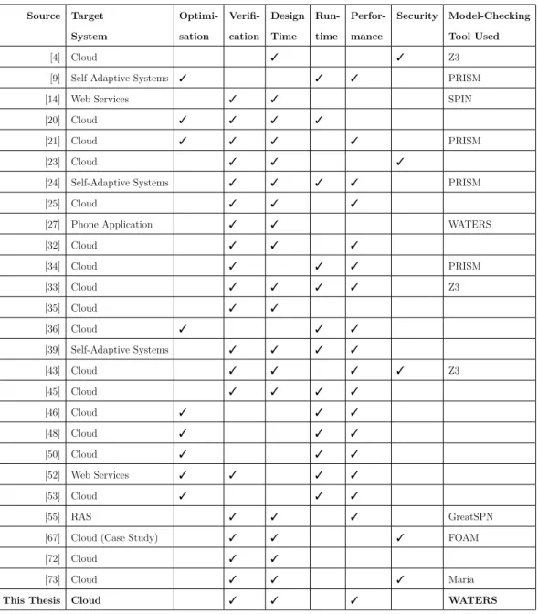
This section discusses the existing frameworks which aim to verify or im-prove cloud systems. These are summarised in Table 3.1. To the best of our knowledge, there is limited work on the formal modelling and verification of cloud autoscaling policies. In particular, to our knowledge no research ex-ists that applies model checking to verify cloud horizontal autoscaling using non-probabilistic finite state machines.
The columns are used as follows: the target system is the system which the research applies to. Most apply to cloud systems specifically, but some are ap-plicable to self-adaptive systems in general [9, 39]. Those with a checkmark in the Optimisation column focus on improving the performance or overall qual-ity of the system at runtime, without necessarily providing formal guarantees.
Table 3.1: An overview of relevant frameworks towards providing guarantees for or improving cloud and self-adaptive systems.
Source Target Optimi- Verifi- Design Run- Perfor- Security Model-Checking
System sation cation Time time mance Tool Used
[4] Cloud 3 3 Z3
[9] Self-Adaptive Systems 3 3 3 PRISM
[14] Web Services 3 3 SPIN
[20] Cloud 3 3 3 3
[21] Cloud 3 3 3 3 PRISM
[23] Cloud 3 3 3
[24] Self-Adaptive Systems 3 3 3 3 PRISM
[25] Cloud 3 3 3
[27] Phone Application 3 3 WATERS
[32] Cloud 3 3 3 [34] Cloud 3 3 3 PRISM [33] Cloud 3 3 3 3 Z3 [35] Cloud 3 3 [36] Cloud 3 3 3 [39] Self-Adaptive Systems 3 3 3 3 [43] Cloud 3 3 3 3 Z3 [45] Cloud 3 3 3 3 [46] Cloud 3 3 3 [48] Cloud 3 3 3 [50] Cloud 3 3 3 [52] Web Services 3 3 3 3 [53] Cloud 3 3 3 [55] RAS 3 3 3 GreatSPN
[67] Cloud (Case Study) 3 3 3 FOAM
[72] Cloud 3 3
[73] Cloud 3 3 3 Maria
Those with a checkmark in theVerification column aim to verify if the system will meet its SLA (or in the case of runtime, is meeting its SLA currently). The Design Time and Run Time columns indicate whether the framework is applied at design time or runtime (or both). The Performance and Security columns indicate whether the frameworks focus on performance (availability, response time and throughput) or security (the CIA triad)1. Finally, the Model
Checking Tool used is listed, where applicable.
Evangelidis et al. propose a probabilistic performance model using Discrete Time Markov Chains, focusing on cloud horizontal autoscaling policies [21]. This work used the PRISM model checker, and related CPU utilization with response time using K-Means clustering. Similar to our work, this falls into Wave V (Guarantees under Uncertainty) and in Wave III (Performance Mod-els) of self-adaptation [69]. Instead, we use non-probabilistic modelling, and focus on modelling the mechanics of autoscaling (a bottom-up, “white box” approach).
Heidari et al. present a method for controller synthesis to determine a cloud system configuration that meets an SLA in [25]. In this study the cloud system is modelled using Timed Petri Nets (TPN) and could be extended to other model types. The authors provide an example for maintaining availability in the case of component failure. In contrast, we focus on maintaining availability based on horizontal autoscaling.
Raimondi et al. collected performance information at runtime to detect a state that indicated an SLO was about to be violated [52]. In contrast, we are aiming to predict SLO violations at design time.
Johnson et al. introduce the INVEST framework for efficient incremen-tal verification of probabilistic models, integrating with the PRISM model checker [34]. The authors present a model for the availability/reliability of a multi-tier cloud service given certain probabilities of component failure. Sim-ilar to our work, the test case examines cloud availability. However, their
ample is based on probability of component failure and not autoscaling. They also use probabilistic modelling, whereas we use deterministic modelling.
A closely related work presents a method for incremental verification of adaptive systems using a satisfiability modulo theory (SMT) solver [33]. Again, the system is re-verified after undergoing change at runtime, as required. The authors suggest how the two methods could be integrated.
Idziorek presents a discrete event simulation model to investigate horizontal scaling within a cloud system [31]. This is, however, based on VM-based clouds and on simulation, whereas we focus on container-based clouds and formal verification.
Basset et al. describe a method for composition of stochastic games us-ing probabilistic automata (PA) to improve the performance of autonomous systems [9]. In contrast, this thesis uses regular (non-probabilistic) automata. The Kubernetes community is planning to implement SLO guarantees as part of the SIG-Scalability project [37]. The documentation distinguishes be-tween steady state SLOs (during normal traffic) and burst SLOs (during un-usually high traffic).
Yoshida et al. used theTOSCA (Topology and Orchestration Specification for Cloud Applications) language to model relationships between components of a system. TOSCA was used to specify the service template for a cloud application, which consisted of a topology template (resource structure) and set of plans. TOSCA designs were mapped to state machines and prove that the systems have “leads-to” properties (a class of liveness). This is a useful approach for testing availability [72].
Hinze et al. used WATERS to verify and improve the design of a mobile tourist information system [27]. While this is different from a cloud system, we also hope to improve the design of cloud systems with the same approach. Zeng et al. used Coloured Petri Nets (CPNs) to verify security require-ments for cloud systems [73]. Their system ensures that resources can only be accessed by clients with the appropriate permission level. The focus of the
research is security, whereas this thesis focuses on availability.
A framework to provide cross tenant access control (CTAC) is presented by Alam et al. [4]. The cloud resource mediation service (CRMS) runs as a third-party service and manages access to resources from one tenant to another. The system is modelled using High Level Petri Nets, and verified using SMT-Lib and the Z3 solver. The focus of the research is security, whereas this thesis focuses on availability.
Chareonsuk and Vatanawood proposed a method to formally validate or-chestration of services in the cloud [14]. In this approach the topology and service functionality of the cloud are specified using the TOSCA and BPEL XML-based languages. This specification is then translated into Promela code, and the resulting Promela code is verified by the SPIN model checking tool. Safety properties are specified using linear temporal logic. In contrast, this thesis does not focus on composition of services (primarily an SaaS concern), but rather on the level of PaaS and FaaS.
Vinárek et al. present the FOAM tool for lightweight formal analysis of use cases [67]. They present an example in the context of cloud service providers, but the tool can be used for other domains as well. The use cases are annotated with required conditions (such as the fact that a resource must always be closed after being opened). Then the NuSMV model checker is used to verify that the proposed implementation of the use cases will meet these conditions. This focuses on functional requirements, whereas in this thesis we focus instead on non-functional requirements.
Malik et al. used a combination of model-checking and theorem-proving using High Level Petri Nets (HLPN) to verify cloud management software itself [43]. The focus is on IaaS, particularly the configuration of VMs within the cloud environment. However, the authors do not present an example of a violation; in all the tests given the management software works as expected. The Z3 solver is used as the verification tool.
rela-tionships between cloud application components, and performing the deploy-ment of a VM-based cloud system [20]. The formal modelling is done using an extension to the XML-based specification language called OVF (Open Vi-talisation Format). An evaluation is presented, in which the focus was on the speed of deployment. In contrast, this thesis focuses on the post-deployment behaviour of the cloud.
Klai and Ochi present a method to verify the composition of cloud-based services using Symbolic Observation Graphs (SOGs), Linear Temporal Logic (LTL), Petri Nets and Labelled Kripke Structures (LKS) [35]. The aim is to check whether a set of cloud services will function as expected when composed together. The authors present a class of Petri Net called aresource-constrained open workflow net (RCoWF-net), used in the verification process. In contrast, this thesis focuses on modelling the cloud system itself as opposed to the composition of services running on the cloud.
Lee et al. present the RINGA framework which uses model-checking in self-adaptive software at runtime [39]. The authors present a type of state machine created at design time called a self-adaptive state machine (SA-FSM). This is used to create an adaptive finite state machine (A-FSM) which is then used in a MAPE loop at runtime to make the software self-adaptive. If the trigger conditions are met, an adaptive transition is performed. The RINGA framework was tested using an IoT-based lighting controller, and its performance overhead compared to existing symbolic model checking tools. This is somewhat related to the work of Klein et al. [36] which aimed to help create self-adaptive software, and Johnson et al. [34] which used model-checking at runtime. However, it is perhaps too low-level for this thesis, which focuses on modelling high-level behaviour of a cloud system at design-time only.
The SLAC Management Framework presented by Uriarte et al. verifies that an SLA is internally consistent at design time [64]. It also monitors the cloud system at runtime to check if the SLA is being met, and sends
alerts if there violations. However, this does not seem to check if a cloud design meets the SLA. It also does not take into account actions such as scaling. The authors also focus on IaaS clouds, whereas this thesis focuses on PaaS. In addition, SLAC is a textual language written in terms of constraint satisfaction problems, whereas this thesis focuses on model checking using finite state machines.
Rodríguez and Campos used Petri Nets to model the throughput (perfor-mance) of systems [55]. Specifically, the authors present a technique to esti-mate the throughput of resource-allocation systems (RASs). A cloud system may be viewed, at least partly, as such a system.
Ficco et al. present an extension to UML to allow modelling security in the context of cloud systems [23]. The cloud is represented by a Cloud Component Diagram and Deployment Diagram, which include Use Cases, representing normal and intended user behaviour, and Misuse Cases, which pose a security threat. Mitigation Cases are added to specify how Misuse Cases are han-dled. A useful overview of security modelling frameworks for cloud systems is also provided, notably Abstract State Machine Language, which is based on extended finite state machines, and STATL, a state/transition-based lan-guage. However, the focus of the work is security, whereas this thesis focuses on availability.
Nawaz et al. present a framework to predict possible SLA violations in a dynamic Cloud of Things (CoT) environment [45]. The authors present a framework using probabilistic modelling to predict SLA violations based on events. This requires translating the SLA into a set of rules, and analysing past QoS data. This is used to infer the likelihood of SLA violations given a set of events. The authors also compare the existing event-driven approaches to modelling SLA violations.
3.2
Overview Papers
This section presents papers which provide a summary of relevant topics to this thesis. These are listed also in Table 3.2.
Table 3.2: Overview papers relevant to this thesis.
Citation Topic
[6] Modelling QoS in cloud systems
[61] Web service composition approaches [41] Assuring QoS in reactive systems
[57] Formal verification in cloud systems
[70] Use of formal methods in self-adaptive systems
[71] How to model requirements for self-adaptive systems
Souri et al. present a survey of the recent use of formal methods to ver-ify cloud systems [57]. Notably, the authors have not listed WATERS as a tool used for checking cloud systems. Existing formal approaches are grouped into three categories: specification process algebra, model or property checking and theorem proving [57]. Model checking is further divided into two cate-gories: state-based andaction-based. The state-based approaches use a Kripke Structure, whereas the action-based approaches use a labeled transition system (finite state machine). Making use of this work, this thesis would be added in the category Model Checking - Action Based - Labeled Transition System.
Weyns et al. survey the use of formal methods in self-adaptive systems in-cluding theInternet of Things (IoT) and cloud systems [70]. The authors state that the main focus of these efforts has been performance and reliability, and also note that there is a need for lightweight tools which use formal methods to verify system performance at runtime.
Ardagna et al. provide an overview of Quality of Service (QoS) modelling for cloud systems [6], covering modelling techniques such as wavelet-based methods,regression analysis,filtering,Fourier analysis and kernel based
meth-ods. The focus is on availability, which is also the focus of this thesis.
Mahdavi-Hezavehi et al. review existing approaches to handling multiple Quality Attributes (QAs) in self-adaptive systems [41]. Performance, reliabil-ity, cost, availability and scalability were the most commonly studied QAs. Only one of the studies investigated used automata to model QAs and their characteristics. Model checking was used by 5 of the studies surveyed.
ter Beek et al. discuss the application of formal methods to the composition of Web Services [61]. Web services typically provide a description of their functionality, and formal methods may be applied to verify if the composition of different web services will produce the required behaviour. In particular, the authors mention automata - which is the focus of our work.
Yang et al. provide an overview of requirements modelling for adaptive systems (including cloud systems) [71]. The approaches modelling tools used included KAOS, pi*, and so on. The authors do not seem to list a Discrete Event Simulation tool such as WATERS. In Figure 12 the authors provide a table of Requirements Engineering activities. Our project in in the category Modelling requirements.
3.3
Investigative Papers
This section presents papers investigate an aspect of cloud computing which may be useful to model formally. These are summarised in 3.3.
Table 3.3: Investigative papers relevant to this thesis.
Source Topic
[26] Elasticity in Cloud Computing
[46] Scaling in the presence of resource-intensive tenants
[49] Effect of garbage collection in Java on SLOs
[54] Sharing resources amongst cloud providers [74] Scaling of Node.js applications in the cloud
Patros et al. investigated the effects of scaling an application in a multi-tenant cloud where other multi-tenants consume a maximum amount of resources [46]. The authors introduce a set of applications called Cloud Burners, which de-liberately consume a maximum number of allocated resources. There is one for CPU, Cache, Resident Memory, Disk I/O and Network I/O. The results indicate that scaling does not always work as expected. For example, scaling horizontally may cause further network congestion, making the application perform worse when the Network I/O is the bottleneck.
Patros et al. reported the effects of different garbage collection policies on meeting SLOs in a cloud environment [49, 47]. The authors created a Java test program calledCloudGC for testing garbage collection settings versus SLOs in the cloud. Using CloudGC the authors tested various parameters and policies and reported the relationships between them.
Patros et al. introduced a method to re-order requests in the cloud to better meet SLOs [48]. This favours the scenario where there are multiple connected clients (many users or devices communicating with the same cloud).
Rameshan et al. [53] present the Stay-Away framework which helps en-sure SLA compliance for multi-tenant clouds. If a batch application (that is, not performance-sensitive) is co-located with a performance-sensitive appli-cation, Stay-Away throttles the batch application as required to ensure the performance-sensitive application has enough resources to meet its SLOs.
Hu et al. present a framework to provide formal verification as a service in a cloud system [28]. This is designed to take advantage of cloud features such as scaling, pay-as-you-go, and to be used my multiple clients (multi-tenant). Using this, models are made as bigraphs using a graphical interface. The models are then converted to SPIN code and verified using the SPIN model checker, since the tools for checking bigraphs directly were not mature yet. To be clear, the authors present a general-purpose verification service which runs on the cloud; they are not verifying a cloud system itself. This thesis investigates modelling the cloud system itself.
Jindal et al. modelled the performance of micro-services based cloud ap-plications by testing the individual micro-services to determine their capacity in terms of requests per second, before SLOs are violated [32]. This was done using the Terminus tool.
Podolskiy et al. used machine-learning algorithms to find the best configu-rations for horizontal and vertical scaling to ensure SLOs are met and cost is kept to a minimum [50].
Klein et al. explain the brownout concept [36]. Similar to an electrical brownout, this refers to reducing the amount of work the software does, in order to maintain availability during peak periods.
Souri et al. present the Graphical Symbolic Modelling Toolkit (GSMT) model-checking framework for distributed systems. This allows creating a model via a graphical user interface as either labelled transition systems or Kripke structures. The tool then generates the SMV code for the model, and the verification is done using the NuSMV tool. The authors also present a useful summary of existing tools for the same purpose. However, WATERS is not listed in the summary.
Theoretical Model
This chapter presents our theoretical model for a cloud system. This is a basis for the formal guarantees in the WATERS models presented in Section 5. As far as possible, we have based this model on Kubernetes. We focus on Platform as a Service (PaaS) and Function as a Service (FaaS) clouds, since providing guarantees under uncertainty in Infrastructure as a Service (IaaS) and Software as a Service (SaaS) has been studied in existing work, for example by Wang et al. [68] and Chen et al. [15].
If the theoretical model is accurate enough, then the WATERS verification results provide formal guarantees of SLA compliance (or non-compliance). It should be noted that the theoretical model is currently rather limited and acts as a proof-of-concept of our proposed methodology; the models can be expanded in the future.
The theoretical model for a cloud comprises the workload, cloud (pods), SLAand themaster. Note that we work at the level of pods, not worker pods. The cloud users submit a number of requests each second. These requests are delegated to the pods of the cloud. The pods process the requests, which takes a certain duration per request. The master scales out or in by creating or removing a pod when the queue lengths reach the relevant thresholds. The SLA specifies the maximum response time for processing requests. Each of these components is explained in detail below.
4.1
Workload
Let us represent the workload as a set of stateless requests from users to the cloud. Each request asks the cloud system to perform a task (for example, return a webpage) which consumes various amounts of cloud resources, such as RAM, CPU or disk space. Let us assume the SLA specifies a maximum rate at which the requests may be sent by users per second, namely RP Smax.
Let us assume that each request takes the maximum possible processing time P Tmax; this way the worst case scenario is modelled. In a real-world
cloud, each request may take a different amount of time to process [48] (for example, a request to encrypt a file may take longer than a request to return a static webpage).
Let us consider two shapes of workload, aconstant load and a square wave
load. In a constant load, there is a fixed maximum rate at which requests are sent, RP Smax. Each second, the number of requests entering the cloud
is a number between zero and this maximum. In a square wave load, this maximum rate is first set to a high level RP Smax(high)for a set amount of time
Thigh, then a low level RP Smax(low) for a set amount of time Tlow; this pattern is then repeated indefinitely.
Note that we do not model the network between the user’s machine and the cloud, since we are considering the cloud provider’s perspective. Therefore packets that are dropped by the network between the cloud and client are not modelled.
4.2
Cloud
Let us define the cloud as a set of pods. A pod represents a single Kubernetes container within the cloud. Let as assume this is a single-tenant cloud, and that each pod runs one instance of a single (stateless) application.
When a request is submitted to the cloud, it is delegated to exactly one of the pods, and is appended to the queue of the designated pod. Every second,
the pod processes a certain number of requests and removes them from its queue. Let us assume that the queue length has no limit.
Since each request takes P Tmax (Processing Time maximum) to process,
the total number of requests processed by a single pod per second is 1/P Tmax.
Again, we assume the worst case scenario, that the processing time is the maximum possible value.
Let us assume that the cloud will always have at least one pod running (podsmin = 1) and there is a maximum limit of pods podsmax. Let us also
assume that requests are allocated to pods via a round-robin scheme. That is, the first request is allocated to the first pod, the second to the next pod, and so on. Formally, if the number of pods currently on is podscurrent, the i-th
request is assigned to pod number ((i−1) mod podscurrent) + 1.
4.3
SLA
Let us define an SLA as a single SLO: a maximum response time of RTmax.
Thus, all requests must be satisfied within RTmax seconds.
Let us determine the maximum possible queue length in order to satisfy the SLO. We assume that the requests are always served in a first-come-first-server order. This means that if there are too many existing requests in the queue (for any pod), the new request will not be serviced in time and the maximum response time SLO will be violated. This occurs when:
QL×P Tmax > RTmax
where QL is queue length of any pod, including the new request to be checked. This can be seen as a variation of Little’s Law [40].
So the SLO is satisfied if and only if, for each pod, QL×P Tmax ≤RTmax.
This can be rearranged as:
QL≤ RTmax
P Tmax
(4.1)
SLO:
QLmax=
RTmax
P Tmax
(4.2)
Therefore in order to meet the SLO, the queue length of any pod must not be greater than QLmax as defined above.
4.4
Master
The master represents the controlling logic and self-adaptive strategy used by the cloud. For this theoretical model, let us consider only horizontal autoscal-ing. Let us assume that the master scales out by one pod when the queue of the last pod reaches a threshold QLscale−up. Let us define the threshold in
terms of percentage of the maximum queue length QLmax as defined in (4.2).
Let us introduce a scale threshold parameter STup between 0 to 1, such that:
QLscale−up =QLmax×STup (4.3)
For example ifSTupis 0.80, the master will scale out when the queue length
of the last pod is at 80% or more of its capacity. Let us also assume that the master will scale down (in) by one pod when the queue of the first pod reaches a threshold QLscale−down. Let us introduce a parameter STdown from 0 to 1.
QLscale−down =QLmax×STdown (4.4)
For example if STdown is 0.20, the master will scale out when the queue
length of the last pod is at 20% or less of its capacity.
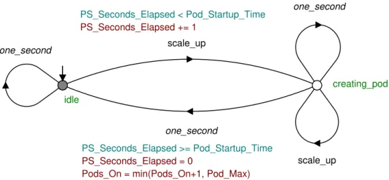
Let us also assume that pods take a certain amount of time to start up and start processing requests after being created. This time in seconds is Tpod−startup.
Let us assume that the master does the check for scaling only at set time intervals. Let us introduce a parameter Tscale−check to indicate that this check
to avoid the case where the master starts a pod while one is already starting up.
This model is based on the KubernetesHorizontal Pod Autoscaler(HPA) [1], but there are some notable differences. Firstly, the Kubernetes HPA scales based on CPU usage, and not queue length. We assume, however, that CPU usage is directly proportional to queue length. The relationship between queue length and CPU utilisation could perhaps be determined experimentally, but due to time constraints this was not done—related work has shown that ex-pected response times based on CPU utilization can be predicted using Ma-chine Learning [50]. Secondly, Kubernetes also does not scale in or out by exactly one pod each time, but rather sets a desired number of pods, and creates or removes pods to meet this desired number1. Scaling by one pod at a time was the simplest to model, and is reasonable for a small number of maximum pods as we have in our experiments (the maximum is 4). However, for a large number of maximum pods (such as 100), this assumption would cause the model to be very inaccurate, since the cloud might scale by a large number of pods at a time. Finally, Kubernetes does not consider CPU met-rics from pods that have been recently created, as those metmet-rics may not be available or stable yet. This is controlled by the “–horizontal-pod-autoscaler-initial-readiness-delay” parameter, which has a default value of 30 seconds. This could be addressed by having the model ignore the queue length of pods that have not been active for a certain amount of time; however, this does add complexity to the model, and the calculation is already complicated due to the CPU vs. length-difference issue explained earlier. The next chapter describes how this theoretical model is represented in WATERS.
1
System Model
This chapter presents our system model. These are extended finite state ma-chines created using WATERS, based on the theoretical model presented in the previous chapter. This chapter presents the system model for the master, workload, cloud, SLA, and Horizontal Pod Autoscaler.
The naming convention used within the models is that states, automata and transitions are spelled in lowercase, for example user_submits_requests;
variables and named constants are capitalised, for example Submitted.
The requirements for our final models were that they had to compile and perform a property check (for all properties) within 10 seconds such that the model is convenient to use. We also aimed to satisfy the generally desirable properties for a DES: the models should be controllable, nonblocking, and con-tain no livelocks, deadlocks or control loops. These properties were confirmed by checking the final models using the WATERS controllability check, conflict check, deadlock check and control loop check features.
The model consists of automata that are synchronised on common events. Thus, if two or more automata use the same event, the event can only fire if it is enabled in all automata, and it fires in each automaton at the same time (in lock-step). For example, because the event user_submits_requests is present
in both the master and user automata, it can only fire if user is in idle and master is in waiting (discussed in Sections 5.1 and 5.2).
We developed two separate, but similar models in WATERS. The first rep-resents a cloud system running a default NGINX installation. The second represents a cloud running a custom Node.js application. The NGINX cloud has a fast and variable response time, and was tested using a constant max-imum load (RP S_max). The Node.js application has a fixed and relatively
slow response time, and was tested using a square wave load. Both WATERS models can be downloaded from our GitHub repository1. We will firstly
ex-plain the NGINX model fully, then exex-plain differences for the Node.js model in Section 5.6.
5.1
Master
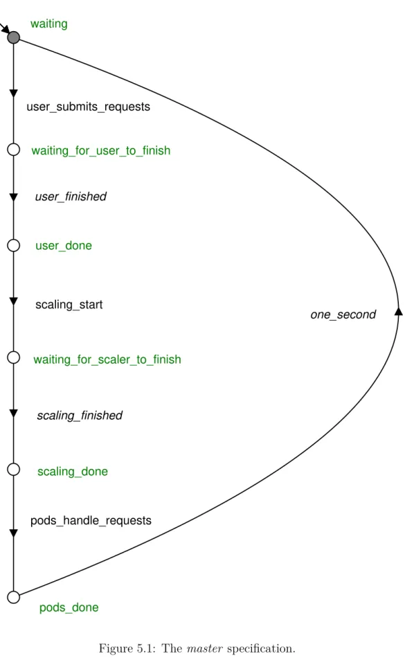
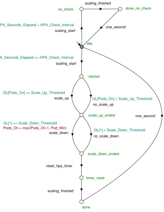
The master automaton controls the overall flow of the model. This is shown in Figure 5.1. The automaton starts in the statewaiting and transitions to the state waiting_for_user_to_finish via event user_submits_requests. This event
is synchronised in the automatonuser, which is described in Section 5.2. Once the user automaton has finished, it triggers the event user_finished. This lets
the master automaton transition to stateuser_done. The master then triggers
the event scaling_start and goes to state waiting_for_scaler_to_finish. The
scaling is then done by the automaton horizontal_pod_autoscaler, which is
described in Section 5.4. The horizontal_pod_autoscaler automaton triggers
the eventscaling_finished when done, which lets the master transition to state
scaling_done. The master then triggers the transition pods_handle_requests.
This is synchronised to the pod automata, which handle requests and remove them from their queue. This is described in Section 5.3. Finally, the master transitions back to state waiting via the event one_second. This represents
one second of time. The loop can then continue indefinitely.
scaling_done waiting_for_user_to_finish waiting_for_scaler_to_finish waiting user_done pods_done pods_handle_requests scaling_finished one_second user_submits_requests user_finished scaling_start
5.2
Workload
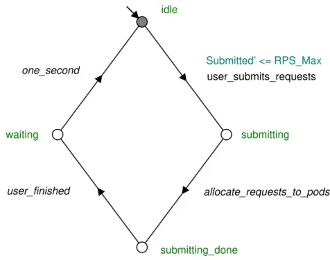
The workload is controlled by the plant called user. This plant represents the users of the cloud as a whole. Every second the users send a certain number of requests to the cloud. Theuser automaton for this design is shown in Figure 5.2. The corresponding pod_queue automaton for this is shown in
Figure 5.3. Note the guard condition for the user_submits_request event in
the user automaton: Submitted0 ≤ RPS_Max. The prime notation indicates
the next state of the variable. Therefore this guard ensures that the transition is allowed only if the next value of Submitted (that is, Submitted0) is less than
RPS_Max. Therefore when the transition is finished and the automaton is in
state submitting, the value of Submitted is between zero and RPS_Max. Note
that RPS_Maxis set to the maximum number of requests per second allowed.
This highlights one of the key uncertainties that model checking allows us to explore: the incoming traffic to the cloud. Each second there may be any number of requests up to RPS_Max. For a period of 2 minutes and a
maximum of 299 requests per second, the number of possible patterns is 300120
(300 possible values each second, for 120 seconds): it is infeasible to test all possible variations with a load testing tool; however, model checking can test this rapidly.
The number of pods currently active (on) is represented by the variable
Pods_On, which is always betweenPod_Min and Pod_Max. There is one pod_
queue automaton for each pod, identified by Pod_Index from 1 toPods_On.
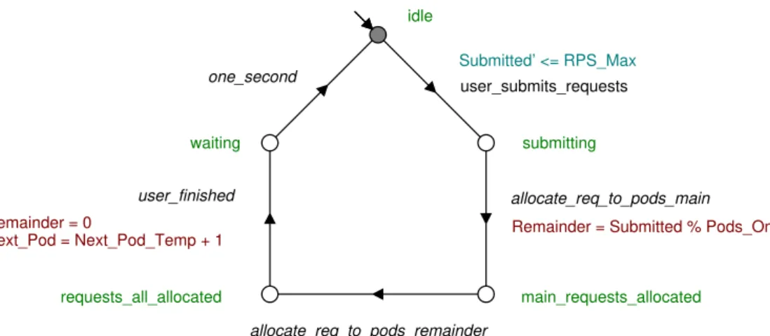
Thepod_queue automaton (Figure 5.3) represents the queue of a pod with
index Pod_Index. Since we assume round-robin load-balancing, we divide the
submitted requests evenly among the pods that are currently active. On the event allocate_requests_to_pods, there are two possible transitions: if the pod
is on (that is, Pods_On ≥ Pod_Index) then the action is executed: QL[Pod_
Index] = min(QL_Max+1,QL[Pod_Index] +Submitted/Pods_On). This means
the queue length of the pod will be the minimum of: 1) QL_Max+1, which is
submitting_done submitting idle waiting Submitted’ <= RPS_Max user_finished user_submits_requests one_second allocate_requests_to_pods
Figure 5.2: The user automaton. Submitted’ is the next state of Submitted. The Submitted variable represents the number of requests submitted in this second. RPS_Maxis the maximum number of requests per second.
Pods_On, which is the current length with the number of requests submitted
this second divided by the number of available pods added. The reason for using the minimum is to avoid the model being blocking on this transition. QL_
Max+1 is the maximum value of theQL[Pod_Index] variable, and the transition
will be blocked if the assigned value is over this maximum. There is no need to consider any higher values, since a property check will fail for any value higher than QL_Max. If the pod is off (that is,Pods_On <Pod_Index), then the pod
queue length stays the same.
One downside of this approach is that, if the amount of requests submitted does not divide evenly into the number of pods currently on (for example, 5 requests were submitted and 2 pods were on), then the remainder is lost. However, for high values of RP Smax such that RP Smax P odsmax, this is
assumed to be acceptable.
However, the compilation and verification times were quite high in some instances. This is probably due to the large possible number of values of the

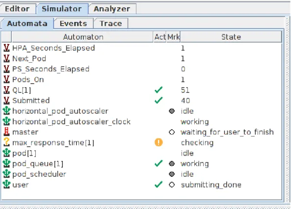
![Figure 5.13: The property max _ response _ time[1] shown in the right-hand pane.](https://thumb-us.123doks.com/thumbv2/123dok_us/10980425.2985949/54.892.333.602.111.395/figure-property-response-time-shown-right-hand-pane.webp)