Blade-Vortex Interaction Noise Controller Based on
Miniature Trailing Edge Effectors
Sara Modini and Giorgio Graziani
Department of Mechanical and Aerospace Engineering, University of Rome La Sapienza, Via Eudossiana 18, 00184, Rome, Italy.
Giovanni Bernardini and Massimo Gennaretti
Department of Engineering, University Roma Tre, Via della Vasca Navale 79, 00146, Rome, Italy. (Received 17 November 2016; accepted 2 February 2018)
The present work focuses on the alleviation of Blade Vortex Interaction (BVI) noise annoyance through a control methodology generating high-frequency aerodynamic BVI counter-actions. The low-power requirements make the Micro-Trailing Edge Effectors (MiTEs) particularly suited for this kind of application. The controller layout is set by observing the BVI scenario while the actuation law is efficiently synthesized through a process based on an analytical unsteady sectional aerodynamic formulation. The validation of the proposed control methodology is carried out through numerical investigations of a realistic helicopter main rotor in flight descent, obtained using computational tools for potential-flow aerodynamic and aeroacoustic analyses based on boundary element method solutions. In order to capture the aerodynamic influence of MiTEs through potential-flow simulations, the MiTEs are replaced by trailing edge plain flaps which provide equivalent aerodynamic responses. Results concerning the proposed controller capability to alleviate high-frequency blade loads and subsequent emitted noise from BVI events are presented and discussed.
NOMENCLATURE
c Blade chord
cL Sectional lift coefficient
cBV I
L BVI perturbation lift coefficient
cL Vector of blade loads
e Nondimensional distance of the flap
hinge from the mid-chord
G Gain matrix
f J Cost function
k Reduced frequency
M Mach number
nBV I BVI representative harmonics [/rev]
Nb Number of rotor blades
r/R Nondimensional spanwise position from
rotor hub
R Blade radius
T Transfer matrix
U Fluid velocity
W Optimal control weighting matrix
x/c Nondimensional chordwise position from
leading edge
δ Flap deflection
δ Vector of control variables
µ Advance ratio
ρ Air density
ψ Blade azimuth
Ω Rotor angular speed
Subscripts
n Harmonic order
u Control variables
z Controlled variables
1. INTRODUCTION
The Blade Vortex Interactions (BVIs) are one of the most critical issues for public acceptance of helicopters. The
in-teraction phenomena between rotor blades and wake typically occurs during low-speed flight descent, when tip vortices re-leased by a blade impinge on or pass in close proximity to the following blades. Impulsive aerodynamic loads are produced on the blade surfaces, giving rise to a particularly annoying acoustic disturbance.
In the last few decades, BVI noise reduction has been the subject of many research efforts, proposing both passive and active control methods. The latter, like higher harmonic con-trol (HHC), individual blade concon-trol (IBC), or active trailing-edge flap control, use relatively low-frequency actuation inputs to produce blade response by increasing the miss distance i.e., the relative distance between vortex and blade, thus alleviating BVI effects. However, the success of these techniques, shown to be capable of considerable BVI noise reduction,1–4 often corresponds to increased rotor vibrations.
With the goal to overcome this drawback, past papers pro-posed and investigated a BVI- noise control methodology based on an innovative principle of action, a generation of unsteady aerodynamic loads aimed at cancelling out directly those caused by BVIs: anti-BVI loads. Based on an optimal linear-quadratic multi-cyclic local controller capable of gener-ating anti-BVI loads through multi-harmonic pitch motion of a suitable blade portion, that procedure offered the opportu-nity of reducing BVI noise without the drawback of structural vibrations.4, 5
Numerical investigations have shown promising results, al-though suggesting further developments concerning its feasi-bility and the efficiency of the process for control law de-termination. These two issues are examined in the present work, with the introduction of realistic control actuation de-vices on the blade, and with the application of an efficient semi-analytical method for the controller identification.
The generation of anti-BVI loads requires the availability of actuation devices able to operate at frequencies higher than those provided by traditional IBCs. In this framework, MiTEs
seem to be suitable candidates for the realistic application of such a method for BVI-noise control. Specifically, the MiTEs or microtabs are a modern version of the Gurney flap, which was first developed and applied to racing cars by Dan Gurney in the 1970s. In spite of the small size—from1% to5% of the chord length—this tab, placed at the trailing edge orthog-onal to the chord line, is capable of providing an increase of
30% in the baseline maximum lift coefficient.7–9A deployable Gurney flap requires low actuation power and is easy to imple-ment making it suitable for the integration in smart rotors. The MiTEs could be considered a low-power alternative to a plain flap for performance enhancement10 and for noise and vibra-tion control applicavibra-tions.11–13 Furthermore, it has been proven that MiTEs require1/55 power to deploy as compared to a plain-flap,14 as well as having good actuation performance.15 Today, helicopter rotors equipped with MiTEs able to operate at the frequency range required by anti-BVI loads generation are not yet produced. However, the Active Gurney Flap (AGF) project funded under the CleanSky demonstration program ‘GRC1-Innovative rotors blades’, prototype validation tests on a scaled model rotor blade demonstrated that a new concept of miniaturized active Gurney flap can operate at blade rotating speed of1600rpm, with actuation frequencies up to150 Hz (see http://cordis.europa.eu/result/rcn/184746 en.html).
In this framework, the present paper concerns preliminary investigations about the exploitation of high-frequency actua-tion of suitable MiTEs configuraactua-tions for BVI noise control. The actuation harmonics are those of the BVI loads, with am-plitudes given by a closed-loop control law determined through an efficient computational procedure based on the Theodorsen airfoil theory.16 Specifically, this theory is applied to derive an analytical form of the system matrix required by the op-timal multi-cyclic local controller algorithm. The controller performance is assessed by application to a realistic rotor flight condition, numerically investigated through an aerody-namic tool based on a free-wake boundary element method approach for potential flow solution (BEM),17 and an aeroa-coustic tool based on the Farassat 1A Formulation.18, 19 In the potential-flow aerodynamic simulations, the MiTEs are re-placed by suitable trailing-edge (TE) flaps, which have been demonstrated to be capable of providing equivalent aerody-namic responses.14, 20, 21
2. BVI NOISE CONTROL METHODOLOGY
In the present work, the idea is to control the BVI noise by directly suppressing its aerodynamic sources, namely the high-frequency unsteady loads induced on the blade surface by the tip vortex crossing. This is accomplished by control actions that are able to generate equal and opposite unsteady loads (anti-BVI loads).
Since this kind of control procedure requires high-frequency control action localized only where and when BVIs occur, MiTE systems have been selected as controllers suitable for this purpose as they guarantee easy implementation on the rotor blades and low-power requirements. However, the mi-crotabs will be replaced by suitable trailing-edge flaps, sized accordingly with literature results in order to guarantee equiv-alent aerodynamic responses.14, 20, 21
The controller determination consists of the following steps: First, the BVI scenario is achieved by BEM numerical simu-lation of the rotor flight condition; Next the TE flaps layout suitable for anti-BVI loads generation is defined, and the con-troller synthesis is carried out by application of the Theodorsen theory which provides the analytic transfer matrix relating the
cyclic components of the trailing-edge flap deflection with the corresponding sectional loads harmonics. Finally, MiTE actu-ation providing aerodynamic responses similar to those given by controlled TE flaps is identified.
In the following, the methodology developed for the control law determination is outlined. The identification of the BVI scenario, the selection of the TE-flaps layout, and the MiTE-TE flaps equivalence are discussed in the next section, for a specific rotor configuration of interest.
2.1. Control Law Synthesis
The multi-cyclic optimal control laws driving the selected layout of microtabs are identified through an analytical process based on the Theodorsen theory.
Starting from the widely applied multi-harmonic optimal control approach introduced by Johnson for reduction of heli-copter vibrations,22 a closed-loop control algorithm is defined to determine the TE-flap actuation suitable for generating the anti-BVI loads and, hence, to suppress the BVI acoustic an-noyance sources.
Due to the inherently time-periodic nature of the problem, the multi-harmonic optimal control consists of minimizing the cost function:
J =zTWzz+uTWuu; (1) whereuis the vector collecting the actuated harmonics of the control variables (input) to be determined,zis the vector of the harmonic quantities to be reduced (output), whileWzandWu are weighting matrices that are defined to get the best com-promise between control effectiveness and control effort. This control approach involves only the harmonics of input and out-put variables, without concerning the evolution of transients. In the present problem,u≡δis the vector of sine and cosine components of the TE-flap motion harmonics actuated for BVI control, whilez≡cLcontains sine and cosine components of the BVI loads harmonics to be reduced (namely, those earlier identified by the BVI scenario analysis discussed in the next section).
The minimization of the cost function is obtained under the constraint of compatibility with the governing equation sys-tem represented through the following linearized relationship between control variables and BVI harmonic loads, about the current input state,δn−1,
cLn =cLn
−1 +Tn−1(δn−δn−1); (2)
whereTn−1is the (gradient) transfer matrix.
Combining Eq. (1) with Eq. (2) and minimizing the result-ing cost function gives the followresult-ing optimal control:
δn=Guδn−1−GzcLn−1; (3) where the gain matrices are expressed as:
Gu=D TTn−1WzTn−1; Gz=D TTn−1Wz; with: D= (TTn−1WzTn−1+Wu) −1 .
A drawback in using this local controller lies in the signifi-cant computational cost for the evaluation of the gradient ma-trix at each step of the control process (note that the evaluation of the gradient matrix requires the determination of the sensi-tivities of the BVI loads harmonics with respect to each flap
motion harmonic considered in the control actuation). Here, for the sake of computational efficiency, the transfer matrix, T, is derived analytically from the Theodorsen theory, which simulates the linear unsteady aerodynamics of the blade sec-tion representative of the BVI events.
Specifically, as predicted by the Theodorsen theory, in the frequency domain the following equation relates the lift coef-ficient,cL, to TE-flap deflection,δ16
˜
cL =−jkF4+k2F1
+ 2C(k) [F10+ 0.5jkF11] ˜δ; (4) whereC(k)is the lift deficiency function given in terms of the reduced frequencyk =ω b/U, withω, bandU denoting the frequency of the periodic motion, the semi-chord length and the airfoil velocity, respectively. TheF-coefficients are geo-metric constants, depending only on the flap size through the normalized relative distance, e, between flap hinge and mid-chord F1=− 1 3 p 1−e2+ecos−1e; F4=−cos−1e+e p 1−e2; F10= p 1−e2+ cos−1e; F11= cos−1e(1−2e) + p 1−e2(2−e). Imposing a multi-harmonic TE-flap motion:
δ(t) = X nBV I δnBV IS sinωnBV It+δ nBV I C cosωnBV It ;
whereωnBV I =nBV IΩ(multiples of the rotor angular speed,
Ω) are the actuated control frequencies, (namely, the BVI load harmonics determined in the prior BVI scenario analysis, dis-cussed in the next section). ForcL =−cBV IL (anti-BVI loads), Eq. (4) provides the input-output constant transfer matrix,T, to be applied in the control algorithm (Tn−1=Tin Eq. (2)).
In this work, for the sake of simplicity and computational efficiency, the weighting matrix Wu is assumed to be null, and all of the BVI loads harmonics are assumed to be equally important for the problem under consideration (Wz=I). Un-der these assumptions, the gain matrices becomeGu=Iand Gz=T−1, and the corresponding control law reads:
δn=δn−1−T−1cLn−1; (5) which has to be used in a recursive way as a closed-loop con-trol process when used in a real-world application, or coupled with accurate aerodynamics-aeroacoustics solvers for valida-tion purposes. Indeed, starting with the uncontrolled output (for instance, the BVI loads harmonics predicted by the uncon-trolled rotor BEM solution) at eachn-th control step, measured BVI loads and corresponding control inputs are used as a feed-back to update the control law until convergence. Note that, the time interval between each control step should be long enough to allow rotor aerodynamics to reach the steady-periodic state corresponding to the updated control inputs.24
Note that two different transfer matrices and control laws are determined for advancing-side and retreating-side BVI events, and that the actuation is accomplished when the blade passes in the vicinity (see BVI windowing introduced in the BVI sce-nario analysis in the next section).
2.2. MiTE Actuation
Once the control laws able to suppress the BVI loads aris-ing in the advancaris-ing and in the retreataris-ing sides are identified,
to save power, the control actions given by the TE-flap har-monic deflections requested by the controller, can be obtained by dynamically actuating suitable MiTE systems. Indeed, sev-eral authors assure through numerical and experimental stud-ies that aerodynamic equivalence between TE-flap harmonic deflections and dynamic actuation of suitably sized MiTEs is achievable.20, 21 In this framework, it must be noted that the oscillations of the plain flap must be replaced by harmonically deploying a MiTE-pair using a ramp-like motion. The pair should consist of a microtab placed on the upper side of the blade surface and a microtab placed on the lower one.
In the next section, this concept is applied to a controller considered for the rotor configuration numerically examined.
3. NUMERICAL RESULTS
The numerical investigation concerns the assessment of the effectiveness of the controller based on the low-power MiTEs high-frequency actuation—numerically simulated as equiva-lent TE-flap devices—to alleviate high-frequency rotor BVI loads and related emitted noise.
To this purpose, the considered rotor case is the low-speed steady flight descent corresponding to the HELISHAPE Euro-pean Project Datapoint 70 for the EC/ONERA 7A main rotor, that has been extensively tested at the DNW wind tunnel.25 Specifically, the rotor examined is a four-bladed main rotor with blades having a rectangular planform and aspect ratio equal to15. The flight condition considered is a6-deg descent with angular speedΩ = 101rad/s, advance ratioµ= 0.166, and rotational tip Mach numberM = 0.615.
For the blade surface discretized with28panels chordwise,
36panels spanwise, and a time step corresponding to2-degree azimuth displacement, a free-wake BEM potential-flow solver is applied for aerodynamic simulations.17 Furthermore, the ro-tor aeroacoustics is predicted by a numerical tool based on the Farassat 1A formulation.19All the computational tools used in the present work have been extensively validated in the past.17 With the aim of focusing on the analysis of the effectiveness of the proposed BVI controller, for the sake of simplicity and with no loss of generality, the blades are assumed to be rigid (the au-thors have verified that the proposed high-frequency anti-BVI control action remains decoupled from the aeroelastic blade dynamics26).
3.1. Controller Setting
As mentioned in the previous section, the proposed method-ology starts with the analysis of the BVI scenario occurring during the rotor flight, for the selection of the optimal con-troller setting.
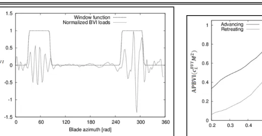
Since BVIs are high-frequency phenomena typically local-ized in two regions of the rotor disk (one in the advancing side and one in the retreating side), the BVI aerodynamic effects on rotor blades must first be estimated by evaluation of the so-called BVI perturbation lift coefficient,cBV IL , which is ob-tained by windowing these regions and filtering-out the low-frequency (< 8/rev) blade loads. As an in-depth description of the analysis of the BVI loads characteristics has been pre-sented by the authors in the past,5hereafter only the key steps of the process are explained.
For the considered flight condition, Fig. 1 depicts the time-history of the BVI perturbation lift coefficient evaluated by the BEM solver at the blade cross section r = 0.75R, with R
denoting the blade radius. It shows that advancing and retreat-ing BVIs are localized around the azimuth positionψ = 60◦
Figure 1. Time history of the high-frequency lift coefficient components at r= 0.75R.
Figure 2.BVI loads harmonic components atr= 0.75R.
andψ= 280◦, respectively, with both covering approximately
one-sixth of the blade revolution period. Next, the Fourier analysis of the time-bounded BVI perturbation lift coefficient is accomplished to evaluate the harmonics multiple of the win-dowing width, namely,nBV I = 12,18,24,30,36/rev, which are presented in Fig. 2.
The spectral analysis of the filtered signal allows evaluation of the BVI effects distribution along blade span in terms of the average power of the normalized sectional load, namely,
cBV IL M2. The blade region most severely affected by BVI events is where the control device should be placed in order to achieve the largest BVI noise abatement.
Figures 3 and 4 show, respectively, the APBVI radial distri-butions and the MiTE/TE-flap configurations correspondingly selected for control applications. The blade regions most af-fected by BVIs are located at 75% and 85% of the span for the advancing and retreating side events, respectively. Thus, the simplest configurations consist of one single control de-vice at r = 0.75R andr = 0.85R. In addition, two more complex configurations are examined: a dual-system with the simultaneous activation of both devices and a five-tab system distributed along the outer-half blade (see Fig. 4).
The numerical investigation of the controller performance is based on potential-flow solutions for the determination of blade loads; hence, microtabs are replaced with suitable equiv-alent TE-flaps. Specifically, the action of each single control-device is simulated by a trailing-edge plain flap having the
Figure 3.APBVI radial distribution.
Figure 4.Sketch of the selected control-device systems.
Figure 5.Uncontrolled and controlled perturbation BVI lift coefficient atr= 0.75R.
chord equal to 1/10 of the blade chord and length equal to
6/100 of the blade radius—the equivalence between the ap-plied TE-flaps and MiTEs is discussed later. The control is ac-tuated only where BVIs occur by suitable windowing process, with a frequency spectrum coinciding with that characterizing the BVI loads.
3.2. Assessment of Controller Efficiency
First, the single flap centred atr= 0.75Ris considered, and the control law able to provide anti-BVI loads is identified by activating the harmonics matching the BVI loads ones, namely
nBV I = 12,18,24,30,36/rev (see Fig. 2).
Figure 6.Effect of controller in terms of BVISPL variations achieved by TE flap atr= 0.75R.
Figure 7.Effect of controller in terms of BVISPL variations achieved by TE flap atr= 0.85R.
in Fig. 5, which depicts uncontrolled and controlled perturba-tion BVI lift coefficient at the75% blade radial station. It re-veals that the implemented control law is capable of alleviating significantly BVI loads occurring both at the advancing and at the retreating side.
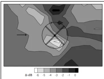
The corresponding impact on the noise emitted by the whole rotor is illustrated in Fig. 6 in terms of BVISPL, i.e. the overall sound pressure level taking into account the acoustic harmon-ics most affected by BVI loads, namely those forn≥7/rev. It depicts the contour plot of the variation of BVISPL distribution (∆−dB) due to controller action evaluated on a carpet of187
microphones located1.25Rbelow the rotor disk. It demon-strates a good acoustic effectiveness of the actuated control device, with the highest control efficiency obtained where BVI noise peaks are present. Up to3dB of noise peak reduction is achieved.
Next, the effectiveness of the control based on the actuation of the TE-flap placed atr = 0.85Ris shown in Fig. 7. As compared with Fig. 6, the application of a more external flap seems to provide higher alleviation of the emitted noise on a wider area of the examined region. This is probably due to the higher impact that this flap may have on the BVI loads aris-ing on the outer blade sections, which generate higher acoustic effects. Note that for both single TE-flap configurations exam-ined, limited noise increase occurs in very small extent regions.
Figure 8.Effect of controller in terms of BVISPL variations achieved by the dual-flap system.
Figure 9.Effect of controller in terms of BVISPL variations achieved by the multi-flap system.
With the aim of enhancing the controller performance, the TE-flaps applied individually are actuated simultaneously, giv-ing rise to a dual-flap configuration. Figure 8 shows the cor-responding distribution of noise variation that presents higher BVI noise alleviation, particularly in terms of wider peak abatement below the rotor advancing side region. Note that, the simultaneous actuation of a number of control-devices re-quires a suitable control-law identification procedure: a differ-ent transfer matrix, T, is determined for each control-device by considering the BVI impulsive loads arising at the blade ra-dial station where the specific control device is located. Once all the gain matrices,GδandGcL, that yield the optimal con-trol performance are identified, the concon-trol law for each device is applied, with feedback sectional BVI loads provided by the BEM aerodynamic rotor simulation with actuated TE-flaps.
However, as expected, the best controller performance for BVI noise suppression is achieved by exploiting the multi-flap system. Indeed, as illustrated in Fig. 9, it is capable of positively affecting BVI sectional loads on the outer half blade, thus providing noise reduction peaks that reach−6dB of BVISPL. In addition, it also reduces the extent of those in-creased noise areas appearing when a single flap is actuated (see Figs. 6 and 7).
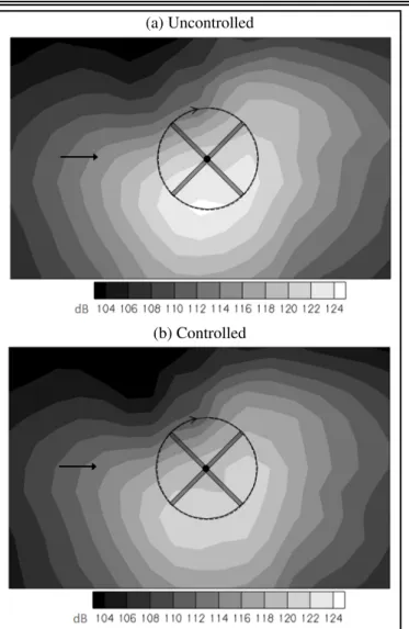
Finally, the control performance is examined in terms of the complete OASPL distribution (including the low-frequency
(a) Uncontrolled
(b) Controlled
Figure 10. OASPL contour plots of noise emitted by uncontrolled rotor and controlled rotor equipped with the multi-flap system.
noise components). The results are presented in Fig. 10, where the acoustic footprints predicted with and without control ac-tion are compared. It demonstrates that a remarkable OASPL reduction up to5dB is achieved throughout the domain inves-tigated. It is not surprising the lower OASPL reduction with respect to the abatement of BVISPL observed in Fig. 9. In-deed, the implemented controller is developed with the aim of reducing the high-frequency noise content related to the BVI phenomena—which is particularly annoying for the human ear—without assuring reduction of the noise low-frequency content.
3.3. Equivalent MiTE actuation
The numerical investigations have proven that the BVI con-trol method presented is effective, particularly when multi-device configurations are actuated. However, considering the required high-harmonic actuation, a controller based on a multi-flap systems is not feasible. More realistically, this high-frequency control could be performed by application of an equivalent MiTE system that would require less actuation power.
For instance, Fig. 11 shows the TE-flap deflection applied for the controlled BVI noise of Fig. 6, along with the aerody-namically equivalent ramp-like MiTE motion obtained through simultaneous activation of the upper and lower microtabs.
The equivalence has been determined observing that mi-crotab actuation can produce ON/OFF configurations (only
Figure 11. TE-flap deflection requested by the controller, and equivalent MiTE deployment.
corresponding to the fully-deployed and fully-retracted posi-tions, respectively), and setting MiTEs size such that their full deployment aerodynamically corresponds to the average de-flection of the corresponding flap motion (10degrees for the case in Fig. 11). Considering the lift gain predicted by the thin airfoil Glauert theory for a statically deflected trailing-edge plain flap, using empirical relations it is possible to derive the microtab height that must be selected to provide the equiv-alent aerodynamic response27(1.5%-chord height for the case in Fig. 11). Following results available in past literature,28the MiTE effectiveness loss due to high-frequency dynamic actua-tion has been assumed to be comparable to the TE-flap one, as indicated by the lift deficiency function.
Finally, it has been estimated that, for the control action re-lated to Fig. 6, the equivalent MiTE actuation would require an amount of power that is about1% of that required by the controller based on the TE-flap motion.
4. CONCLUDING REMARKS
An optimal multi-cyclic controller aiming at alleviating BVI impulsive loads and corresponding noise annoyance has been presented and validated. For the sake of computational ef-ficiency, trailing-edge flaps have been considered as control devices, but the aerodynamic equivalence with MiTEs has been observed and analysed. Due to the challenging require-ments of the proposed BVI control approach, trailing edge mi-crotabs are found to be suitable control devices because of their low-power actuation and high-frequency actuation capa-bility. A novel methodology for the control law determination has been presented and applied, introducing an efficient pro-cedure for the input-output transfer matrix evaluation based on the Theodorsen sectional unsteady aerodynamics theory. Effectiveness and robustness of the proposed controller have been assessed by application to a realistic rotor configuration in low-speed flight descent, remarkably affected by BVIs. It has been shown that it provides satisfactory abatement of the high-frequency noise—namely, the sound pressure levels mostly af-fected by BVI phenomena—with peak reduction reaching6dB when a system of multi TE-flaps is applied. The results of this study demonstrate that the proposed control approach is a vi-able method to reduce BVI noise.
ACKNOWLEDGEMENTS
The authors thank the ENAC (Italian Civil Aviation Author-ity) for the funding of this research.
REFERENCES
1 Straub, F. K., Kennedy, D., Stemple, A., Anand, V. R., and Birchette, T., Development and Whirl Tower Test of the SMART Active Flap Rotor, Proceedings of SPIE: The International Society of Optical Engineering, Vol. 5388, 2004, pp. 202–212. https://dx.doi.org/10.1117/12.562645 2 Straub, F. K., and Hassan, A. A., Aeromechanical
Con-siderations in the Design of a Rotor With Smart Material Actuated Trailing Edge Flaps, American Helicopter Soci-ety 27th Annual Forum, Washington, DC, USA, 1996. 3 Viswamurthy, S. R., and Ganguli, R., Optimal
Place-ment of Piezoelectric Actuated Trailing-Edge Flaps for He-licopter Vibration Control,Journal of Aircraft, Vol. 46, (1), 2009, pp. 244–253. https://dx.doi.org/10.2514/1.41918 4 Anobile, A., Bernardini, G., and Gennaretti, M.,
Investiga-tion on a High-Frequency Controller for Rotor BVI Noise Alleviation, International Journal of Acoustics and Vibra-tion, Vol. 21, (3), 2016, pp. 239–248.
5 Modini, S., Graziani, G., Bernardini, G., and Gennaretti, M., Parallel Blade-Vortex Interaction Modelling for Heli-copter Rotor Noise Control Synthesis, International Jour-nal of Aeroacoustics, Vol. 13, (7), 2014, pp. 587–606. https://dx.doi.org/1260/1475-472X.13.7-8.587
6 Modini, S., Graziani, G., Bernardini, G., and Gennaretti, M., Parallel Blade-Vortex Interaction Analyses and Ro-tor Noise Control Synthesis, 19th AIAA/CEAS Aeroacous-tics Conference Proceedings, Berlin, Germany, May 26–29, 2013. https://dx.doi.org/10.2514/6.2013-2291
7 Li, Y., Wang, J., and Zhang, P., Influences of Mounting An-gles and Locations on the Effects of Gurney Flaps,Journal of Aircraft, Vol. 40, (3), 2003, pp. 494–498.
8 Maughmer, M. D., and Bramesfeld, G., Experimen-tal Investigation of Gurney Flaps, Journal of Aircraft, Vol. 45, (6), 2008, pp. 2062–2067.
9 Cole, J. A, Vieira, B. A. O., Coder, J. G., Premi, A., and Maughmer, M. D., An Experimental Investigation into the Effect of Gurney Flaps on Various Airfoils, 49th AIAA Aerospace Sciences Meeting, AIAA 2011-1250, Orlando, Florida, USA, January 4–7, 2011.
10 Kinzel, M., Maughmer, M. D., and Lesieutre, G. A., Miniature Trailing-Edge Effectors for Rotorcraft
Perfor-mance Enhancement, Journal of the American
He-licopter Society, Vol. 52, (2), 2007, pp. 146–158. https://dx.doi.org/10.4050/JAHS.56.146
11 Kinzel, M., Maughmer, M. D., and Duque, E. P. N.,
Numerical Investigation on the Aerodynamics of
Oscillating Airfoils with Deployable Gurney Flaps, AIAA Journal, Vol. 48, (7), 2010, pp. 1457–1469. https://dx.doi.org/10.2415/1.J050070
12 Stalewski, W., and Sznajder, J., Computational In-vestigations of Active Flow Control on
Helicopter-Rotor Blades, Journal of KONES Powertrain
and Transport, Vol. 21, (2), 2014, pp. 281–288. https://dx.doi.org/10.5604/12314005.1133905
13 Min, B. Y., Sankar, L. N., Rajmohan, N., and Prasad, J. V. R., Computational Investigation of Gurney Flap Effects on Rotors in Forward Flight, Jour-nal of Aircraft, Vol. 46, (6), 2009, pp. 1957–1964. https://dx.doi.org/10.2514/1.41918
14 Palacios, J.,Kinzel, M., and Overmeyer, A., Active Gurney Flaps: Their Application in a Rotor Blade Centrifugal Field, Journal of Aircraft, Vol. 51, (2), 2014, pp. 473–489. 15 Lee, H. T., and Kroo, I. M., Computational Investigation of
Airfoils with Miniature Trailing Edge Control Surfaces, Pa-per AIAA 20041051,42nd AIAA Aerospace Sciences Meet-ing and Exhibit ProceedMeet-ings, Reno, Nevada, USA, January 5–8, 2004.
16 Theodorsen, T., and Garrick, I. E., General Potential The-ory of Arbitrary Wing Sections,NACA REPORT 452, 1979. 17 Gennaretti, M., and Bernardini, G., Novel Boundary Inte-gral Formulation for Blade-Vortex Interaction Aerodynam-ics of Helicopter Rotors, AIAA Journal, Vol. 45, (6), 2007, pp. 1169–1176.
18 Ffowcs Williams, J.E., and Hawkings, D.L., Sound Gen-erated by Turbulence and Surfaces in Arbitrary Motion, Philosophical Transactions of the Royal Society, Vol. A264, 1969, pp. 321–342.
19 Farassat, F.,Derivation of Formulations 1 and 1A of Faras-sat, NASA TM-2007-214853.
20 Nakafuji, D. T. Y., Van Dam, C. P., Smith, R. L., and Collins, S. D., Active Load Control for Airfoils using Mi-crotabs, Journal of Solar Energy Engineering, Vol. 123, 2001, pp. 282–289.
21 Baek, P., and Gaunaa, M., Modeling the Temporal Re-sponse of a Microtab in an Aeroelastic Model of a Wind Turbine, 49th AIAA Aerospace Sciences Meeting, AIAA 2011-348, Orlando, Florida, USA, January 4–7, 2011. 22 Johnson, W., Self-Tuning Regulators for Multicyclic
Con-trol of Helicopter Vibration, NASA TP-1996, 1982. 23 Hariharan, N., and Leishman, J. G., Unsteady
Aerodynam-ics of a Flapped Airfoil in Subsonic flow by Indicial Con-cepts, AIAA-95-1228-CP.
24 Patt, D., Liu, L. and Friedmann, P. P., Rotorcraft Vibration Reduction and Noise Predictions Using a Unified Aeroe-lastic Response Simulation Journal of the American Heli-copter Society, Vol. 50, (1), 2005, pp. 95–106.
25 Splettstoesser, W., Niesl, F., Cenedese, F., Nitti, F., and Pa-panikas, D. G., The HELINOISE aeroacoustic rotor test in the DNW test documentation and representative results, DLR-Mitteiling, 1993.
26 Modini, S., Graziani, G., Bernardini, G., and Gennaretti, M., Synthesis of a Rotor Noise Controller by Parallel Blade-Vortex Interaction Aeroelastic Modeling, ASME 2014 Pressure Vessels and Piping Conference Proceedings, Vol. 4,PVP2014-28258, Anaheim, California, USA, July 20–24, 2014.
27 Kentfield, J. A. C., The Potential of Gurney Flaps for Im-proving the Aerodynamic Performance of Helicopter Ro-tors,AIAA-93-4883-CP.
28 Padthe, A. K., Active Vibration and Noise Alleviation in Rotorcraft using Microflaps, Ph.D. Thesis, The University of Michigan, 2011.