SERVICE MANUAL
AIR-CONDITIONER
UNDER CEILING / CONSOLE TYPE
RAV-SM562XT-E / RAV-SM562AT-E
RAV-SM802XT-E / RAV-SM802AT-E
April, 2006
CONTENTS
1. SPECIFICATIONS... 1
2. CONSTRUCTION VIEWS ... 3
3. SYSTEMATIC REFRIGERATING CYCLE DIAGRAM ... 4
4. WIRING DIAGRAM ... 5
5. SPECIFICATION OF ELECTRICAL PARTS ... 6
6. REFRIGERANT R410A ... 7
7. CONTROL BLOCK DIAGRAM ... 15
8. OPERATION DESCRIPTION ... 16
9. TROUBLESHOOTING CHART ... 21
10. DETACHMENTS ... 27
11. EXPLODED VIEWS AND PARTS LIST ... 32
Note :
This Service Manual describes explanation for the Under Ceiling 1 console type indoor unit. For the combined outdoor unit, refer to the following Service Manual.
Outdoor unit Model name SVM to be referred RAV-SMXX0AT-E A03-007
RAV-SPXXXAT-E A03-014 RAV-SMXX1AT-E A05-001 RAV-SMXX2AT-E A05-018
1. SPECIFICATIONS
1-1. Indoor Unit (Flexi Type)
Model RAV-SM562AT-E RAV-SM802AT-E Heating capacity (kW) 5.0 6.7 8.95-8.20 13.15-12.06 1.87 2.72 (W/W) 2.67 2.46
Energy efficiency class * D E
Energy rating * 2.5 1.5 (A) 8.13-7.46 12.91-11.84 Pure white Appearance Model -Panel color -Height (mm) Width (mm) Outer Depth (mm) dimension Height (mm) Width (mm) Depth (mm)
Total weight Main unit (kg)
Ceiling panel
Heat exchanger Finned tube
Fan Centrifugal Centrifugal
Fan unit Standard air flow (m3/h) 14.0 / 12.0 / 10.0 18.5 / 13.5 / 10.7
Motor (W) 50
Air filter Attached main unit
Controller Attached main unit (WH-H2UE)
Gas side (mm) 12.7 15.9
Dimensions pipe
Liquid side (mm) 6.4 9.5
Drain port (mm) VP16
Sound level (dB¥A) 43 / 39 / 36 46 / 42 / 37
Electrical characteristics Ceiling panel (Sold separately) Indoor unit Outdoor unit RAV-SM562XT-E RAV-SM802XT-E Cooling capacity Power supply (kW) 5.6 1 phase 230V (220-240V) 50Hz 8.0
Cooling Running current (A)
Power consumption (kW)
Power factor (%)
EER
Heating Running current
(W/W) Energy efficiency class *
Energy rating * Power consumption (kW) Power factor (%) COP Main unit Ceiling panel (Sold separately) Main unit (kg) H/M/L
Sound power level
H/M/L H/M/L (dB¥A) 95 94 1.70 2.67 95 94 3.29 3.00 C D 3.0 2.5 208 208 1093 1093 633 633 - -- -- -23 23 - -50 58 / 54 / 51 61 / 57 / 52 * IEC standard ** AS standard
• Operation characteristic curve
<Cooling> <Heating>
• Capacity variation ratio according to temperature
<Cooling> <Heating> 0 0 1520 40 60 70 80 100 2 4 6 8 10 12 14 Compressor speed (rps) Current (A) • Conditions Indoor : DB27˚C/WB19˚C Outdoor : DB35˚C Air flow : High Pipe length : 7.5m 230V RAV-SM562XT-E 0 0 1520 40 60 80 90 100 2 4 6 8 10 12 14 Compressor speed (rps) Current (A) RAV-SM802XT-E RAV-SM562XT-E • Conditions Indoor : DB20˚C Outdoor : DB7˚C/WB6˚C Air flow : High
Pipe length : 7.5m 230V 50 55 60 65 70 75 80 85 90 95 100 105 32 33 34 35 36 37 38 39 40 41 42 43 Outsoor temp. (˚C) Capacity ratio (%) • Conditions Indoor : DB27˚C/WB19˚C Indoor air flow : High Pipe length : 7.5m 0 10 20 30 40 50 60 70 80 90 100 110 120 -14 -12 -10 -8 -6 -4 -2 0 2 4 6 8 10 Outsoor temp. (˚C) Capacity ratio (%) • Conditions Indoor : DB20˚C Indoor air flow : High Pipe length : 7.5m
2. CONSTRUCTION VIEWS
2-1. Indoor Unit
Front panel
Knock out system
For stud bolt (Ø8 – Ø10) For stud bolt (Ø6)
Grille air inlet Back body
Installation plate
Mount plate
M10 Suspention bolt
Wireless remote control Knock out system
200 Min 1093 1015 742 450 20 20 330 165 Ø74 70 Min 633 460 57 18 160 633 208 1093
3. SYSTEMATIC REFRIGERATING CYCLE DIAGRAM
3-1. RAV-SM562XT-E / RAV-SM802XT-E
Indoor unit Outdoor unit TCJ sensor Air heat exchangerTC sensor Refrigerant pipe at liquid side Outer dia. ∅B Refrigerant pipe at gas side Outer dia. ∅A Packed valve Outer dia. ∅B Packed valve Outer dia. ∅A Max 30m Cooling Heating
Outer diameter of refrigerant pipe Gas side ∅A Liquid side ∅B
12.7 mm 6.4 mm Model 562XT-E RAV-SM 802XT-E 15.9 mm 9.5 mm Note :
This Service Mamual describes explanation for the Under Ceiling 1 console type indoor unit. For the combined outdoor unit, refer to the following Service Manual.
Outdoor unit Model name SVM to be referred RAV-SMXX0AT-E A03-007
RAV-SPXXXAT-E A03-014 RAV-SMXX1AT-E A05-001 RAV-SMXX2AT-E A05-018
Color Identification BRW RED WHI YEL BLU BLK GRY PNK ORN GRN&YEL GRN PUR : : : : : : : : : : : : BROWN RED WHITE YELLOW BLUE BLACK GRAY PINK ORANGE GREEN& YELLOW GREEN PURPLE
SIMPLE CHECK POINTS FOR DIAGNOSING FAULTS
Diagnosis result
Check to see if OPERATION indicator goes on and off when the main switch or breaker is turned on.
Check the power supply voltage between 1 - 2 (Refer to the name plate.) Chack the fluctuate voltage between 2 - 3 (DC15 to 60V)
Check to see if the fuse blows out. (Check the varistor. : R22, R21) Check the voltage at the No.8 pin on CN13 connector of the infrared receiver. (Check the transformer and the power supply circuit of the rated voltage.) Check the voltage at the brown lead of the louver motor.
(Check the transformer and the power supply circuit of the rated voltage.)
Check items OPERATION indicator Terminal block Fuse 6.3A DC 5V DC 12V
1
2
3
4
5
1 2 2 1 3 4 5 6 7 8 9 10 1 2 3 4 5 6 7 8 9 10 1 2 3 4 5 6 7 8 9 10 1 2 3 4 5 6 7 8 9 10 INFRARED RA YS RECEIVE AND INDICA TION P ARTS SWITCH PCB MCC-1428B BRW RED ORN YEL PNK BLU BLU WHI BLU BLU BLU BLU BLU BLU BLU BLU CN13 CN07 CN100 CN402 J401 C01 R01 DB01 C02 DC12V IC03 C501 R405 R21 R22 SG01 F01 T6.3A FUSE 250VAC R09 R507 CR401 RY401 R506 CR502 RY501 CR501 CN05 CN03 CN01 CN10 CN11 CN401 CN23 FOR FLOAT SWITCH(OPTION) When you use float switch you should cut J401
HEAT EXCHANGER SENSOR (TCJ) THERMO SENSOR (TA) HEAT EXCHANGER SENSOR (TC) CN101 CN25
1
2
4
5
3
3 2 1 3 2 1 3 2 1 3WHI GRY GRY
WHI RED WHI RED BLK BLK BLK BLK BLK BLK BLK BLKP04 CN30 CN31 WHI RED BRW POWER SUPPLY CIRCUIT C15 IC04 DC5V 5 4 3 2 1 5 4 3 2 1 5 4 3 2 1 5 4 3 2 1 1 2 3 1 2 3 1 2 3 1 2 3 1 2 3 6 6 5 4 3 2 1 5 4 3 2 1 6 6 GRY YEL BLU PUR GRY 100”C FAN-MOTOR
FOR DRAIN PUMP (OPTION) MCC-1428A INDOOR UNIT LOUVER MOTOR OUTDOOR UNIT GRN&YEL INDOOR TERMINAL BLOCK 1 2 1 2 1 2 1 2 2 1 2 1 2 1 2 1
4. WIRING DIAGRAM
Indoor Unit
5. SPECIFICATION OF ELECTRICAL PARTS
Indoor Unit
No. Parts name Type Specifications
1 Fan motor (for indoor) AFP-220-50-4A Output (Rated) 50 W, 220 – 240 V
2 Grille motor MP35EA DC 12 V
3 Thermo. sensor (TA-sensor) 550 mm 10 kΩ at 25°C
4 Heat exchanger sensor (TC-sensor) ∅6 mm, 500 mm 10 kΩ at 25°C
(5) After completion of installation work, check to make sure that there is no refrigeration gas leakage.
If the refrigerant gas leaks into the room, coming into contact with fire in the fan-driven heater, space heater, etc., a poisonous gas may occur. (6) When an air conditioning system charged with a
large volume of refrigerant is installed in a small room, it is necessary to exercise care so that, even when refrigerant leaks, its concentration does not exceed the marginal level.
If the refrigerant gas leakage occurs and its concentration exceeds the marginal level, an oxygen starvation accident may result. (7) Be sure to carry out installation or removal
according to the installation manual.
Improper installation may cause refrigeration trouble, water leakage, electric shock, fire, etc. (8) Unauthorized modifications to the air conditioner
may be dangerous. If a breakdown occurs please call a qualified air conditioner technician or electrician.
Improper repair’s may result in water leakage, electric shock and fire, etc.
6-2. Refrigerant Piping Installation
6-2-1. Piping materials and joints usedFor the refrigerant piping installation, copper pipes and joints are mainly used. Copper pipes and joints suit-able for the refrigerant must be chosen and installed. Furthermore, it is necessary to use clean copper pipes and joints whose interior surfaces are less affected by contaminants.
(1) Copper pipes
It is necessary to use seamless copper pipes which are made of either copper or copper alloy and it is desirable that the amount of residual oil is less than 40 mg/10 m. Do not use copper pipes having a collapsed, deformed or discolored portion (especially on the interior surface). Otherwise, the expansion valve or capillary tube may become blocked with contaminants.
As an air conditioner using R410A incurs pressure higher than when using R22, it is necessary to choose adequate materials.
Thicknesses of copper pipes used with R410A are as shown in Table 6-2-1. Never use copper pipes thinner than 0.8 mm even when it is available on the market.
6. REFRIGERANT R410A
This air conditioner adopts the new refrigerant HFC (R410A) which does not damage the ozone layer. The working pressure of the new refrigerant R410A is 1.6 times higher than conventional refrigerant (R22). The refrigerating oil is also changed in accordance with change of refrigerant, so be careful that water, dust, and existing refrigerant or refrigerating oil are not entered in the refrigerant cycle of the air conditioner using the new refrigerant during installation work or servicing time.
The next section describes the precautions for air conditioner using the new refrigerant. Conforming to contents of the next section together with the general cautions included in this manual, perform the correct and safe work.
6-1. Safety During Installation/Servicing
As R410A’s pressure is about 1.6 times higher than that of R22, improper installation/servicing may cause a serious trouble. By using tools and materials exclu-sive for R410A, it is necessary to carry out installation/ servicing safely while taking the following precautions into consideration.
(1) Never use refrigerant other than R410A in an air conditioner which is designed to operate with R410A.
If other refrigerant than R410A is mixed, pressure in the refrigeration cycle becomes abnormally high, and it may cause personal injury, etc. by a rupture.
(2) Confirm the used refrigerant name, and use tools and materials exclusive for the refrigerant R410A. The refrigerant name R410A is indicated on the visible place of the outdoor unit of the air condi-tioner using R410A as refrigerant. To prevent mischarging, the diameter of the service port differs from that of R22
(3) If a refrigeration gas leakage occurs during installation/servicing, be sure to ventilate fully. If the refrigerant gas comes into contact with fire, a poisonous gas may occur.
(4) When installing or removing an air conditioner, do not allow air or moisture to remain in the refrigeration cycle. Otherwise, pressure in the refrigeration cycle may become abnormally high so that a rupture of personal injury may be caused.
Table 6-2-1 Thicknesses of annealed copper pipes
Thickness (mm)
Nominal diameter Outer diameter (mm) R410A R22
1/4 6.35 0.80 0.80
3/8 9.52 0.80 0.80
1/2 12.70 0.80 0.80
5/8 15.88 1.00 1.00
b) Socket joints
Socket joints are such that they are brazed for connections, and used mainly for thick pipings whose diameter is larger than 20 mm.
Thicknesses of socket joints are as shown in Table 6-2-2.
(2) Joints
For copper pipes, flare joints or socket joints are used. Prior to use, be sure to remove all
contaminants. a) Flare joints
Flare joints used to connect the copper pipes cannot be used for pipings whose outer diameter exceeds 20 mm. In such a case, socket joints can be used.
Sizes of flare pipe ends, flare joint ends and flare nuts are as shown in Tables 6-2-3 to 6-2-6 below.
Table 6-2-2 Minimum thicknesses of socket joints
Nominal diameter Reference outer diameter of Minimum joint thickness copper pipe jointed (mm) (mm)
1/4 6.35 0.50
3/8 9.52 0.60
1/2 12.70 0.70
5/8 15.88 0.80
d) Flare processing
Make certain that a clamp bar and copper pipe have been cleaned.
By means of the clamp bar, perform the flare processing correctly.
Use either a flare tool for R410A or conven-tional flare tool.
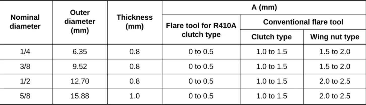
Flare processing dimensions differ according to the type of flare tool. When using a conven-tional flare tool, be sure to secure “dimension A” by using a gauge for size adjustment.
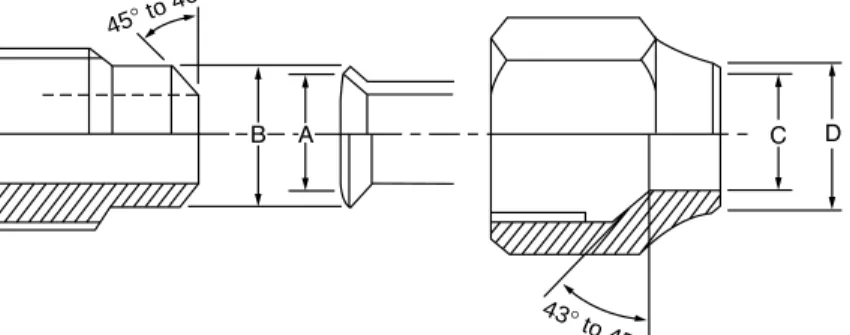
Fig. 6-2-1 Flare processing dimensions 6-2-1. Processing of piping materials
When performing the refrigerant piping installation, care should be taken to ensure that water or dust does not enter the pipe interior, that no other oil other than lubricating oils used in the installed air conditioner is used, and that refrigerant does not leak. When using lubricating oils in the piping processing, use such lubricating oils whose water content has been removed. When stored, be sure to seal the container with an airtight cap or any other cover.
(1) Flare Processing procedures and precautions a) Cutting the pipe
By means of a pipe cutter, slowly cut the pipe so that it is not deformed.
b) Removing burrs and chips
If the flared section has chips or burrs, refrigerant leakage may occur. Carefully remove all burrs and clean the cut surface before installation.
c) Insertion of flare nut
∅D
A (mm)
Conventional flare tool Clutch type Wing nut type
1/4 6.35 0.8 0 to 0.5 1.0 to 1.5 1.5 to 2.0
3/8 9.52 0.8 0 to 0.5 1.0 to 1.5 1.5 to 2.0
1/2 12.70 0.8 0 to 0.5 1.0 to 1.5 2.0 to 2.5
5/8 15.88 1.0 0 to 0.5 1.0 to 1.5 2.0 to 2.5
Table 6-2-3 Dimensions related to flare processing for R410A
Nominal diameter Outer diameter (mm) Thickness
(mm) Flare tool for R410A clutch type
A (mm)
Conventional flare tool Clutch type Wing nut type
1/4 6.35 0.8 0 to 0.5 0.5 to 1.0 1.0 to 1.5
3/8 9.52 0.8 0 to 0.5 0.5 to 1.0 1.0 to 1.5
1/2 12.70 0.8 0 to 0.5 0.5 to 1.0 1.5 to 2.0
5/8 15.88 1.0 0 to 0.5 0.5 to 1.0 1.5 to 2.0
Table 6-2-4 Dimensions related to flare processing for R22
Nominal diameter Outer diameter (mm) Thickness
(mm) Flare tool for R22 clutch type Dimension (mm) A B C D 1/4 6.35 0.8 9.1 9.2 6.5 13 17 3/8 9.52 0.8 13.2 13.5 9.7 20 22 1/2 12.70 0.8 16.6 16.0 12.9 23 26 5/8 15.88 1.0 19.7 19.0 16.0 25 29
Table 6-2-5 Flare and flare nut dimensions for R410A Nominal diameter Outer diameter (mm) Thickness (mm) Flare nut width (mm) Dimension (mm) A B C D 1/4 6.35 0.8 9.0 9.2 6.5 13 17 3/8 9.52 0.8 13.0 13.5 9.7 20 22 1/2 12.70 0.8 16.2 16.0 12.9 20 24 5/8 15.88 1.0 19.4 19.0 16.0 23 27 3/4 19.05 1.0 23.3 24.0 19.2 34 36
Table 6-2-6 Flare and flare nut dimensions for R22 Nominal diameter Outer diameter (mm) Flare nut width (mm) Thickness (mm)
(2) Flare connecting procedures and precautions a) Make sure that the flare and union portions do
not have any scar or dust, etc.
b) Correctly align the processed flare surface with the union axis.
c) Tighten the flare with designated torque by means of a torque wrench. The tightening torque for R410A is the same as that for conventional R22. Incidentally, when the torque is weak, the gas leakage may occur.
Fig. 6-2-2 Relations between flare nut and flare seal surface
When it is strong, the flare nut may crack and may be made non-removable. When choosing the tightening torque, comply with values designated by manufacturers. Table 6-2-7 shows reference values.
Note:
When applying oil to the flare surface, be sure to use oil designated by the manufacturer. If any other oil is used, the lubricating oils may deteriorate and cause the compressor to burn out.
Tightening torque of torque Nominal Outer diameter Tightening torque wrenches available on the market
diameter (mm) N·m (kgf·cm) N·m (kgf·m)
1/4 6.35 14 to 18 (140 to 180) 16 (160), 18 (180)
3/8 9.52 33 to 42 (330 to 420) 42 (420)
1/2 12.70 50 to 62 (500 to 620) 55 (550)
5/8 15.88 63 to 77 (630 to 770) 65 (650)
Table 6-2-7 Tightening torque of flare for R410A [Reference values] 45° to 46
°
43° to 45
6-3. Tools
6-3-1. Required tools
The service port diameter of packed valve of the outdoor unit in the air conditioner using R410A is changed to prevent mixing of other refrigerant. To reinforce the pressure-resisting strength, flare processing dimensions and opposite side dimension of flare nut (For ∅12.70 copper pipe) of the refrigerant piping are lengthened.
The used refrigerating oil is changed, and mixing of oil may cause a trouble such as generation of sludge, clogging of capillary, etc. Accordingly, the tools to be used are classified into the following three types. (1) Tools exclusive for R410A (Those which cannot be used for conventional refrigerant (R22)) (2) Tools exclusive for R410A, but can be also used for conventional refrigerant (R22)
(3) Tools commonly used for R410A and for conventional refrigerant (R22) The table below shows the tools exclusive for R410A and their interchangeability.
Tools exclusive for R410A (The following tools for R410A are required.)
Tools whose specifications are changed for R410A and their interchangeability
R410A air conditioner Conventional air installation conditioner installation
No. Used tool Usage Existence of Whether Whether new equipment
new equipment conventional can be used with for R410A equipment can conventional refrigerant
be used
1 Flare tool Pipe flaring Yes *(Note 1)
2 Copper pipe gauge Flaring by
for adjusting projection conventional flare Yes *(Note 1) *(Note 1)
margin tool
3 Torque wrench Connection of Yes
flare nut 4 Gauge manifold
5 Charge hose
6 Vacuum pump adapter Vacuum evacuating Yes
7 Electronic balance for Refrigerant charge Yes refrigerant charging
8 Refrigerant cylinder Refrigerant charge Yes
9 Leakage detector Gas leakage check Yes
! Charging cylinder Refrigerant charge (Note 2) Evacuating,
refrigerant charge, Yes run check, etc.
(Note 1) When flaring is carried out for R410A using the conventional flare tools, adjustment of projection margin is necessary. For this adjustment, a copper pipe gauge, etc. are necessary.
(Note 2) Charging cylinder for R410A is being currently developed.
General tools (Conventional tools can be used.)
In addition to the above exclusive tools, the following equipments which serve also for R22 are necessary as the general tools.
(1) Vacuum pump (4) Reamer (9) Hole core drill (∅65)
Use vacuum pump by (5) Pipe bender (10) Hexagon wrench
attaching vacuum pump adapter. (6) Level vial (Opposite side 4 mm) (2) Torque wrench (7) Screwdriver (+, –) (11) Tape measure (3) Pipe cutter (8) Spanner of Monkey wrench (12) Metal saw Also prepare the following equipments for other installation method and run check. (1) Clamp meter (3) Insulation resistance tester
6-4. Recharging of Refrigerant
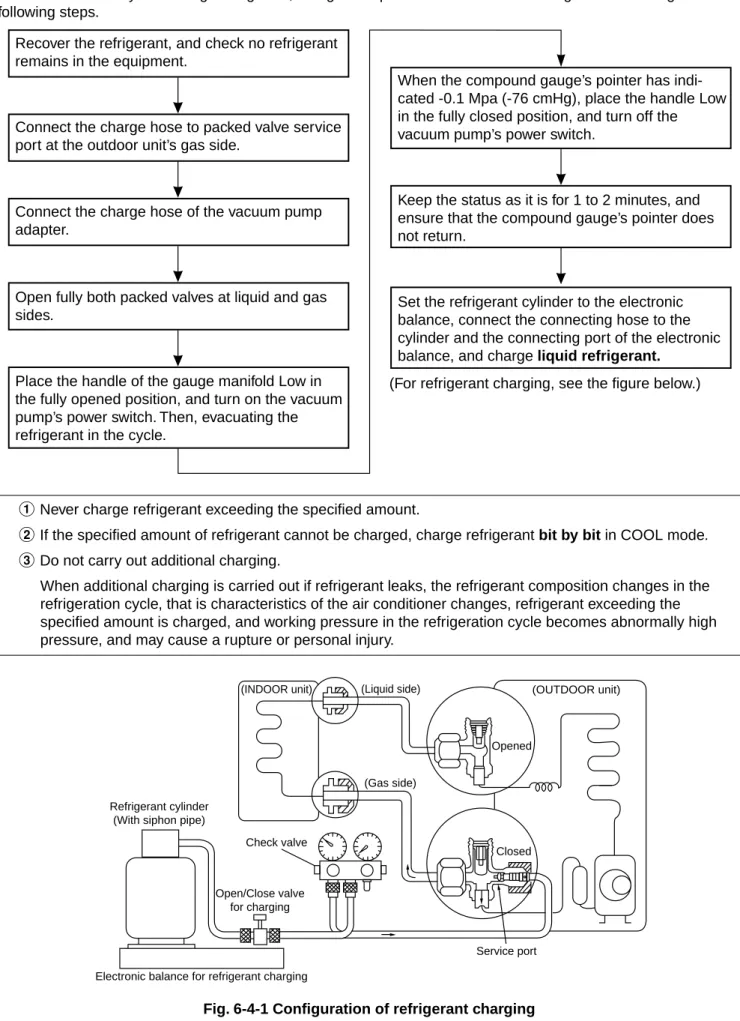
When it is necessary to recharge refrigerant, charge the specified amount of new refrigerant according to the following steps.
Recover the refrigerant, and check no refrigerant remains in the equipment.
Connect the charge hose to packed valve service port at the outdoor unit’s gas side.
Connect the charge hose of the vacuum pump adapter.
Open fully both packed valves at liquid and gas sides.
Place the handle of the gauge manifold Low in the fully opened position, and turn on the vacuum pump’s power switch. Then, evacuating the refrigerant in the cycle.
When the compound gauge’s pointer has indi-cated -0.1 Mpa (-76 cmHg), place the handle Low in the fully closed position, and turn off the vacuum pump’s power switch.
Keep the status as it is for 1 to 2 minutes, and ensure that the compound gauge’s pointer does not return.
Set the refrigerant cylinder to the electronic balance, connect the connecting hose to the cylinder and the connecting port of the electronic balance, and charge liquid refrigerant.
(For refrigerant charging, see the figure below.)
1Never charge refrigerant exceeding the specified amount.
2If the specified amount of refrigerant cannot be charged, charge refrigerant bit by bit in COOL mode.
3Do not carry out additional charging.
When additional charging is carried out if refrigerant leaks, the refrigerant composition changes in the refrigeration cycle, that is characteristics of the air conditioner changes, refrigerant exceeding the specified amount is charged, and working pressure in the refrigeration cycle becomes abnormally high pressure, and may cause a rupture or personal injury.
Fig. 6-4-1 Configuration of refrigerant charging
(INDOOR unit) (Liquid side) (OUTDOOR unit)
Opened
(Gas side)
Closed
Service port Electronic balance for refrigerant charging
Check valve
Open/Close valve for charging Refrigerant cylinder
1Be sure to make setting so that liquid can be charged.
2When using a cylinder equipped with a siphon, liquid can be charged without turning it upside down. It is necessary for charging refrigerant under condition of liquid because R410A is mixed type of refrigerant. Accordingly, when charging refrigerant from the refrigerant cylinder to the equipment, charge it turning the cylinder upside down if cylinder is not equipped with siphon.
Gauge manifold Refrigerant cylinder Electronic balance OUTDOOR unit
[Cylinder with siphon]
[Cylinder with siphon] [Cylinder without siphon]
Fig. 6-4-2
R410A refrigerant is HFC mixed refrigerant. Therefore, if it is charged with gas, the composition of the charged refrigerant changes and the
characteristics of the equipment varies.
6-5. Brazing of Pipes
6-5-1. Materials for brazing (1) Silver brazing filler
Silver brazing filler is an alloy mainly composed of silver and copper. It is used to join iron, copper or copper alloy, and is relatively expensive though it excels in solderability.
(2) Phosphor bronze brazing filler
Phosphor bronze brazing filler is generally used to join copper or copper alloy.
(3) Low temperature brazing filler
Low temperature brazing filler is generally called solder, and is an alloy of tin and lead. Since it is weak in adhesive strength, do not use it for refrigerant pipes.
1Phosphor bronze brazing filler tends to react
with sulfur and produce a fragile compound water solution, which may cause a gas leakage. Therefore, use any other type of brazing filler at a hot spring resort, etc., and coat the surface with a paint.
2When performing brazing again at time of
servicing, use the same type of brazing filler.
6-5-2. Flux
(1) Reason why flux is necessary
•By removing the oxide film and any foreign
matter on the metal surface, it assists the flow of brazing filler.
•In the brazing process, it prevents the metal
surface from being oxidized.
•By reducing the brazing filler’s surface tension,
the brazing filler adheres better to the treated metal. Refrigerant cylinder Electronic balance Siphon Gauge manifold OUTDOOR unit
(2) Characteristics required for flux
• Activated temperature of flux coincides with the brazing temperature.
• Due to a wide effective temperature range, flux is hard to carbonize.
• It is easy to remove slag after brazing.
• The corrosive action to the treated metal and brazing filler is minimum.
• It excels in coating performance and is harmless to the human body.
As the flux works in a complicated manner as described above, it is necessary to select an adequate type of flux according to the type and shape of treated metal, type of brazing filler and brazing method, etc.
(3) Types of flux • Noncorrosive flux
Generally, it is a compound of borax and boric acid.
It is effective in case where the brazing temperature is higher than 800°C.
• Activated flux
Most of fluxes generally used for silver brazing are this type.
It features an increased oxide film removing capability due to the addition of compounds such as potassium fluoride, potassium chloride and sodium fluoride to the borax-boric acid compound.
(4) Piping materials for brazing and used brazing filler/flux
Piping Used brazing Used material filler flux
Copper - Copper Phosphor copper Do not use Copper - Iron Silver Paste flux
Iron - Iron Silver Vapor flux
6-5-3. Brazing
As brazing work requires sophisticated techniques, experiences based upon a theoretical knowledge, it must be performed by a person qualified.
In order to prevent the oxide film from occurring in the pipe interior during brazing, it is effective to proceed with brazing while letting dry Nitrogen gas (N2) flow.
Never use gas other than Nitrogen gas. (1) Brazing method to prevent oxidation
1 Attach a reducing valve and a flow-meter to the Nitrogen gas cylinder.
2 Use a copper pipe to direct the piping material, and attach a flow-meter to the cylinder.
3 Apply a seal into the clearance between the piping material and inserted copper pipe for Nitrogen in order to prevent backflow of the Nitrogen gas.
4 When the Nitrogen gas is flowing, be sure to keep the piping end open.
5 Adjust the flow rate of Nitrogen gas so that it is lower than 0.05 m3/Hr or 0.02 Mpa (0.2 kgf/
cm2) by means of the reducing valve. 6 After performing the steps above, keep the
Nitrogen gas flowing until the pipe cools down to a certain extent (temperature at which pipes are touchable with hands).
7 Remove the flux completely after brazing.
Fig. 6-5-1 Prevention of oxidation during brazing 1 Do not enter flux into the refrigeration cycle.
2 When chlorine contained in the flux remains within the pipe, the lubricating oil deteriorates. Therefore, use a flux which does not contain chloring.
3 When adding water to the flux, use water which does not contain chlorine (e.g. distilled water or ion-exchange water).
4 Remove the flux after brazing.
Nitrogen gas cylinder
M Flow meter
Stop valve
From Nitrogen cylinder
Nitrogen gas Rubber plug Pipe
7. CONTROL BLOCK DIAGRAM
REMOTE CONTROL
Remote Control Operation (START/STOP) Operation Mode Selection AUTO, COOL, DRY, HEAT, FAN ONLY
Temperature Setting Fan Speed Selection ON TIMER Setting OFF TIMER Setting
Louver Auto Swing Louver Direction Setting
ECO Hi power Filter Reset
Infrared Rays Heat Exchanger Sensor (TC)
Heat Exchanger Sensor (TCJ)
Temperature Sensor
Infrared Rays Signal Receiver
Initiallizing Circuit Clock Frequence Oscillator Circuit Power Supply Circuit Noise Filter Relay RY401
Louver ON/OFF Signal
Serial Signal Communication
Hi POWER Display FILTER Sign Display PRE DEF. Sign Display TIMER Display Louver Driver Functions • Louver Control
• 3-minute Delay at Restart for Compressor
• Motor Revolution Control
• Processing
(Temperature Processing)
• Timer
• Drain Pump ON/OFF
• Serial Signal Communication
Remote Control Infrared Rays 36.7 kHz 8 MHz M.C.U.
Indoor Unit Control Panel
OPERATION Display Indoor Fan Motor Louver Motor Float Switch Drain Pump
From Outdoor Unit
Serial Signal Transmitter/ Receiver
8. OPERATION DESCRIPTION
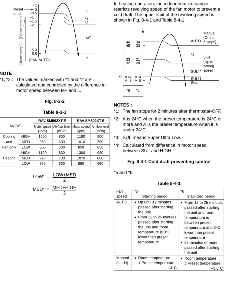
8-3. Air volume control
(1) Operation with [HIGH (H)], [MED (M)], [LOW (L)], or [AUTO] mode is performed by the command from the remote control.
(2) When [FAN] button is set to AUTO, the indoor fan motor operates as shown in Fig. 8-3-1, Fig. 8-3-2 and Table 8-3-1.
<COOL>
NOTE :
*1: The values marked with *1 are calculated and controlled by the difference in motor speed between M+ and L–.
Fig. 8-3-1
8-1. When power supply is reset
(1) Distinction of outdoor units
When the power supply is reset, the outdoors are distinguished, and control is exchanged according to the distinguished result.
(2) Setting of the indoor fan speed
Based on EEPROM data, rspeed of the indoor fan is selected.
Remarks: Air speed
8-2. Operation mode selection
(1) Based on the operation mode selecting command from the remote control, the operation mode is selected.
Table 8-2-1
(2) Automatic Operation
• The air conditioner selects and operates in one of the operating modes of cooling, heating or fan only, depending on the room temperature.
• If the AUTO mode is uncomfortable, you can select the desired conditions manually.
Remote control
Outline of control command
STOP Air conditioner stops. FAN Fan operation COOL Cooling operation
DRY Dry operation HEAT Heating operation AUTO Automatic operation
*1 *1 *1 +3 +2.5 +2 +1.5 +1 +0.5 −0.5 0 M+ Preset temp. °C (Room temp.) − (Preset temp.)
Room temperature in operation Operating condition
The set temperature +1°C or higher (in case that the room is hot) The set temperature –1°C to +1°C
The set temperature –1°C or lower (in case that the room is cold)
Performs the cooling operation at a temperature 1°C higher than the setting.
Performs the fan only operation (low speed) while monitoring the room temperature. When the room temperature changes, the air conditioner will select the cooling or heating mode.
Performs the heating operation at a temperature 1°C lower than the setting.
Cooling operation Fan only operation Heating operation Table 8-2-2
LOW+ = MED+ = LOW+MED 2 MED+HIGH 2 MODEL RAV-SM562XT-E RAV-SM802XT-E
Motor speed Air flow level Motor speed Air flow level (rpm) (m3/h) (rpm) (m3/h)
Cooling HIGH 1060 800 1190 900 and MED 950 690 1010 750 Fan only LOW 800 580 850 650 HIGH 1120 830 1300 980 Heating MED 970 730 1070 800 LOW 820 600 860 650 [FAN AUTO] −0.5 −1 −1.5 −2 *1 *2 −5.0 −5.5 0 Preset temp. M+ H L °C (Room temp.) − (Preset temp.) <HEAT> NOTE :
*1, *2 : The values marked with *1 and *2 are calculated and controlled by the difference in motor speed between M+ and L.
Fig. 8-3-2 Table 8-3-1
8-4. Cool air discharge preventive control
In heating operation, the indoor heat exchanger restricts revolving speed of the fan motor to prevent a cold draft. The upper limit of the revolving speed is shown in Fig. 8-4-1 and Table 8-4-1.
NOTES :
*1: The fan stops for 2 minutes after thermostat-OFF. *2: A is 24°C when the preset temperature is 24°C or more and A is the preset temperature when it is under 24°C.
*3: SUL means Super Ultra Low.
*4: Calculated from difference in motor speed between SUL and HIGH.
Fig. 8-4-1 Cold draft preventing control
*5 and *6: Table 8-4-1 A+4 A+4 A−8 A−8 46 45 34 33 33 21 32 20 *2 *6 *5 Manual (One of 5 steps) L−H (Up to setting speed) AUTO *4 SUL*3 SUL*1 Stop Fan *5 *6
speed Starting period Stabilized period AUTO • Up until 12 minutes
passed after starting the unit
• From 12 to 25 minutes passed after starting the unit and room temperature is 3°C lower than preset temperature Manual • Room temperature (L – H) < Preset temperature
–4°C
• From 12 to 25 minutes passed after starting the unit and room temperature is between preset temperature and 3°C lower than preset temperature
• 25 minutes or more passed after starting the unit
• Room temperature Preset temperature
8-5. Freeze preventive control (Low
temperature release)
The cooling operation (including Dry operation) is performed as follows based on the detected temperature of Tc sensor or Tcj sensor.
When [J] zone is detected for T1 minutes (Following figure), the commanded frequency is decreased from the real operation frequency. After then the
commanded frequency changes every 2 minutes while operation is performed in [J] zone.
In [K] zone, time counting is interrupted and the operation is held.
When [I] zone is detected, the timer is cleared and the operation returns to the normal operation.
Fig. 8-5-1
In heating operation, the freeze-preventive control works if 4-way valve is not exchanged and the condition is satisfied.
Remarks:
Tcj : Indoor heat exchanger sensor temperature
8-6. High-temp release control
The heating operation is performed as follows based on the detected temperature of Tc sensor.
• When [M] zone is detected, the commanded frequency is decreased from the real operation frequency. After then the commanded frequency changes every 30 seconds while operation is performed in [M] zone.
• In [N] zone, the commanded frequency is held.
• When [L] zone is detected, the commanded frequency is returned to the original value by approx. 6Hz every 60 seconds.
Fig. 8-6-1 7 6 5 K I J A (°C) 55 A 52 48 B L N M Tc (°C) T1 Normal 1 minute
8-7. Louver control
(1) Vertical air flow louver
Position of veritcal air flow louver is automatically controlled according to the operation mode. Besides, position of vertical air flow louver can be arbitrarily set by pressing [FIX] button.
The louver position which is set by [FIX] button is stored in the microcomputer, and the louver is automatically set at the stored position for the next operation.
(2) Swing
If [SWING] button is pressed when the indoor unit is in operation, the vertical air flow louver starts swinging. When [SWING] button is pressed, it stops swinging.
8-8. Filter sign display
(1) The operation time of the indoor fan is calculated, the filter lamp (Orange) on the display part of the main unit goes on when the specified time (240H) has passed. When a wired remote controller is connected, the filter reset signal is sent to the remote controller, and also it is displayed on LCD of the wired remote control.
(2) When the filter reset signal has been received from the wired remote control after [FILTER] lamp has gone on or when the filter check button (Temporary button) is pushed, time of the calculation timer is cleared. In this case, the measurement time is reset if the specified time has passed, and display on LCD and the display on the main unit disappear.
Remarks:
8-9. Auto Restart Function
The indoor unit is equipped with an automatic restarting function which allows the unit to restart operating with the set operating conditions in the event of power supply being accidentally shut down. The operation will resume without warning three minutes after power is restored.
This function is not set to work when shipped from the factory. Therefore it is necessary to set it to work.
When the unit is on standby (Not operating)
When the unit is in operation
Operation Motions
Push [TEMPORARY] button for more The unit is on standby. than three seconds.
The unit starts to operate. The green lamp is on. After approx. three seconds,
The unit beeps three times The lamp changes from and continues to operate. green to orange.
If the unit is not required to operate at this time, push [TEMPORARY] button once more or use the remote control to turn it off.
8-9-1. How to set auto restart function
To set the auto restart function, proceed as follows: The power supply to the unit must be on; the function will not set if the power is off.
Push the [TEMPORARY] button located in the center of the front panel continuously for three seconds. The unit receives the signal and beeps three times. The unit then restarts operating automatically in the event of power supply being accidentally shut down.
• While the filter check lamp is on, the
TEMPORARY button has the function of filter reset button.
→
→
Operation Motions
Push [TEMPORARY] button for more The unit is in operation. The green lamp is on. than three seconds.
The unit stops operating. The green lamp is turned off. After approx. three seconds,
The unit beeps three times.
If the unit is required to operate at this time, push [TEMPORARY] button once more or use the remote control to turn it on.
→
→
• While this function is being set, if the unit is in operation, the orange lamp is on.
• This function can not be set if the timer operation has been selected.
• When the unit is turned on by this function, the louver will not swing even though it was swinging automatically before shutting down.
0 PRE.D FILTER Hi POWER TEMPORARY button 3S 0 PRE.D FILTER Hi POWER TEMPORARY button 3S
8-9-2. How to cancel auto restart function
To cancel auto restart function, proceed as follows: Repeat the setting prodedure: the unit receives the signal and beeps three times.
The unit will be required to be turned on with the remote control after the main power supply is turned off.
When the unit is on standby (Not operating)
When the unit is in operation
• While this function is being set, if the unit is in operation, the orange lamp is on.
8-9-3. Power failure during timer operation
When the unit is in Timer operation, if it is turned off because of power failure, the timer operation is cancelled. Therefore, set the timer operation again.
8-10. Filter Check Lamp
When the elapsed time reaches 1000 hours, the filter check lamp indicates. After cleaning the filters, turn off the filter check lamp.
8-10-1. How to turn off filter check lamp
(1) Press [FILTER] button on the remote control. (2) Push [TEMPORARY] button on the indoor unit.
Note:
If [TEMPORARY] button is pushed while the filter check lamp is not indicating, the indoor unit will start the Automatic Operation.
Operation Motions
Push [TEMPORARY] button for more The unit is on standby. than three seconds.
The unit starts to operate. The orange lamp is on. After approx. three seconds,
The unit beeps three times The lamp changes from and continues to operate. orange to green.
If the unit is not required to operate at this time, push [TEMPORARY] button once more or use the remote control to turn it off.
→
→
Operation Motions
Push [TEMPORARY] button for more The unit is in operation. The orange lamp is on. than three seconds.
The unit stops operating. The orange lamp is turned off. After approx. three seconds,
The unit beeps three times.
If the unit is required to operate at this time, push [TEMPORARY] button once more or use the remote control to turn it on.
→
→
0 PRE.D FILTER Hi POWER TEMPORARY button 3S 0 PRE.D FILTER Hi POWER TEMPORARY button 3S9. TROUBLESHOOTING
9-1. Summary of Troubleshooting
9-1-1. Before troubleshooting(1) Required tools/instruments
• e and d screwdrivers, spanners, radio cutting pliers, nippers, etc.
• Tester, thermometer, pressure gauge, etc. (2) Confirmation points before check
1The following operations are normal. a) Compressor does not operate.
• Is not 3-minutes delay (3 minutes after compressor OFF)?
• Does not thermostat turn off?
• Does not timer operate during fan operation?
• Is not outside high-temperature operation controlled in heating operation?
b) Indoor fan does not rotate.
• Does not cool air discharge preventive control work in heating operation? c) Outdoor fan does not rotate or air volume
changes.
• Does not high-temperature release opera-tion control work in heating operaopera-tion?
• Does not outside low-temperature opera-tion control work in cooling operaopera-tion?
• Is not defrost operation performed?
d) ON/OFF operation cannot be performed from remote control.
• Is not forced operation performed?
• Is not the control operation performed from outside/remote side?
2Did you return the cabling to the initial positions?
3Are connecting cables between indoor unit and receiving unit correct?
Trouble → Confirmation of check code by service mode
→ Check defective position and parts. 9-1-2. Troubleshooting procedure
When a trouble occurred, check the parts along with the following procedure.
NOTE :
For cause of a trouble, power conditions or malfunc-tion/erroneous diagnosis of microcomputer due to outer noise is considered except the items to be checked. If there is any noise source, change the cables of the signal line to shield cables.
9-1-3. Outline of Judgment
A primary judgment to detect cause of error exists on the indoor unit or outdoor unit is performed in the following procedure.
<Judgment by flashing display on the indoor unit display part>
The indoor unit monitors operating status of the air conditioner, and if a protective circuit works, contents of the self-diagnosis are displayed with a block restricted to the following cases on the indoor unit display part (Sensor).
Remote
Block display Contents of self-diagnosis Check code control code
–– Operation lamp display flashes. (1Hz) Power failure (In power ON) ––
00 Operation lamp display flashes. (5Hz) Indoor P.C. board 0b to 0F, 11, 12, b5, b6 01 Operation/timer lamp displays flash. (5Hz) Inter-unit cables/transmission system 04
02 Operation/defrost lamp displays flash. (5Hz) Outdoor P.C. board 14 to 19, 1A, 1C 03 Operation/timer/defrost lamp displays flash. (5Hz) Cycle system, etc. 1d, 1E, 1F, 21
–– –– –– 1b, 8b
9-2. Self-Diagnosis by Remote Control
(Check Code)
(1) If the lamps are indicated as shown 00 to 03 in Table 9-1-1, exchanger the self-diagnosis by the remote control.
(2) When the remote control is set to the service mode, the indoor controller diagnoses the
operation condition and indicate the information of the self-diagnosis on the display of the remote control with the check codes. If a fault is detected, all lamps on the indoor unit will blink at 5 Hz and it will beep for 10 seconds (Pi, Pi, Pi....). The timer lamp usually blinks (5 Hz) during the self-diagnosis.
9-2-1. How to use remote control in service mode
(1) Press [CHECK] button with a tip of pencil to set the remote control to the service mode.
• “00” is indicated on the display of the remote control.
• The timer lamp on the indoor unit blinks continuously. (5 times per 1 sec.)
(2) Press [TIMER 8] button.
If there is no fault with a code, the indoor unit will beep once (Pi) and the display of the remote control will change as follows:
• Check the unit with all 35 check codes (00 to 22). as shown in Table 9-2-1.
• Press [TIMER 9] button to change the check code backwards.
If there is a fault, the indoor unit will beep for 10 seconds (Pi, Pi, Pi...).
Note the check code on the display of the remote control.
• 2-digits alphanumeric will be indicated on the display.
• All lamps on the indoor unit will blink. (5 times per 1 sec.)
(4) Press [START/STOP] button to release the service mode.
• The display of the remote control returns to as it was before service mode was engaged.
(3) Press [CLR] button. After service finish for clear service code in memory.
• “7F” is indicated on the display of the remote control. PRESET FAN MODE Hi-POWER ON OFF SET CLR ECO AUTO TIMER CLOCK CHECK RESET FILTER FIX SWING MEMO START/STOP A B AUTOA SET CLR CLOCK CHECK RESET
• Alphanumeric characters are used for the check code. is 5. is 6.
is A. is B. is C. is D.
The indoor thermo sensor (TA) is defective.
Disconnection or short-circuit The indoor heat exchanger sensor (TC) is defective. Disconnection or short-circuit The indoor fan motor or its circuit is defective.
The part other than the above parts on the indoor P.C. board is defective.
EEPROM access error IOL operation
The variation of TC, 5 minutes after starting the compressor, is 2K or less.
The serial signals can not be transmitted and received between indoor and outdoor units.
•The crossover wire is
connected wrongly.
•The serial signal transmitting
circuit on the outdoor P.C. board is defective.
•The serial signal receiving
circuit on the indoor P.C. board is defective.
The operation command signals are not transmitted from the indoor unit to the outdoor unit.
The outdoor thermo sensor (TE) is defective.
Disconnection or short-circuit The outdoor heat exchanger (TD) sensor is defective.
Disconnection or short-circuit The reply serial signal has been transmitted when starting the unit, but stops being transmitted shortly after.
1. Compressor thermo operation
•Gas shortage
•Gas leak
2. Instantaneous power failure
The discharge temperature is
over 120°C.
The IOL operation is defective.
Table 9-2-1
Operation of diagnostic function
Judgement and action Check Block Check
Symptom Unit Condition
code code status
Operation continues. Operation continues. All off Operation continues. All off Operation continues. Operation continues. Operation continues. All off All off Operation continues. All off All off
The lamp on the indoor unit blinks when error is defected. The lamp on the indoor unit blinks when error is defected. The lamp on the indoor unit blinks when error is defected. The lamp on the indoor unit blinks when error is defected. The lamp on the indoor unit blinks when error is defected. The lamp on the indoor unit blinks when error is defected.
The lamp on the indoor unit blinks when error is defected.
The lamp on the indoor unit blinks when error is defected. And it returns to the normal condition when recovering from errors. The lamp on the indoor unit blinks when error is defected. The lamp on the indoor unit blinks when error is defected. The lamp on the indoor unit blinks when error is defected. And it returns to the normal condition when recovering from errors.
The lamp on the indoor unit blinks when error is defected. The lamp on the indoor unit blinks when error is detected.
1. Check the indoor thermo sensor (TA). 2. Check the indoor P.C. board.
1. Check the indoor heat exchanger sensor (TC).
2. Check the indoor P.C. board. 1. Check the connector circuit of the
indoor fan motor (CN10). 2. Check the indoor fan motor. 3. Check the indoor P.C. board. 1. Check the indoor P.C. board.
(EEPROM and peripheral circuits)
Overload operation of refrigerating cycle
1. Check whether or not the TC sensor comes off.
2. Check whether or not it is possible to operate the compressor and the outdoor fan motor.
3. Check gas leak.
1. In the case of the outdoor unit not operating at all;
•Check the crossover cable and
connect it properly.
•Check the outdoor P.C. board.
2. In the case of the outdoor unit operating normally;
•Check whether or not both of serial
LED (Green) and serial LED (Orange) is blinking.
If the serial LED (Green) is not blinking, check the outdoor P.C. board. If the serial LED (Orange) is not blinking, check the indoor P.C. board. If the operation command signals continue
to be transmitted between 2 and 3 of the
indoor terminal block, replace the outdoor P.C. board.
1. Check the outdoor thermo sensor (TE). 2. Check the outdoor P.C. board.
1. Check the outdoor heat exchanger sensor (TD).
2. Check the outdoor P.C. board. 1. Repeatedly turn the indoor unit on and
off with the interval of approx. 10 to 40 minutes. (The check code is not indicated during operation.) And supply gas. (Check gas leak.)
2. The indoor unit operates normally during the check.
If the reply serial signal continues to be
transmitted between 2 and 3 of the
indoor terminal block, replace the outdoor P.C. board.
If the signal stops between them, replace the indoor P.C. board. 1. Check the heat exchanger sensor (TD). 2. Gas purging
When turning on the unit, the normal phase (RST) is detected but T-R waveform has not been detected for 120 seconds or more. Indoor P.C. board The block is unidentifi-able Cable connection Outdoor P.C. board Other parts (including compressor)
The serial signal is not output from outdoor unit to indoor unit.
•Miscabling of inter-unit cables
•Defective serial sending circuit
on outdoor P.C. board
•Defective serial receiving circuit
on outdoor P.C. board
•Compressor case thermo
operation
BUS communication circuit error * BUS communication was
interrupted over the specified time.
Error in 4-way valve system
•Indoor heat exchanger
temperature rise after start of cooling operation.
•Indoor heat exchanger
temperature fall after start of heating operation. Error in other cycles
•Indoor heat exchanger temp
(TC) does not vary after start of cooling/ heating operation.
Coming-off, disconnection or short of indoor temp sensor (TA)
Coming-off, disconnection or short of indoor temp sensor (TC)
Coming-off, disconnection or short of indoor temp sensor (TCJ)
Error in indoor fan system Revolutions frequency error of fan
Error in indoor unit or other positions
1. EEPROM access error Outside error input
Detected by input voltage level from outside devices Outside interlock input Detected by input voltage level from outside devices
Table 9-2-2
Operation of diagnostic function
Judgement and action Block Checkcode Symptom statusUnit Condition
Operation continues. Operation continues (According to remote control of indoor unit) Operation continues. Operation continues. Operation continues. Operation continues. Operation continues. All stop Operation continues. Operation continues. All stop Displayed when error is detected Displayed when error is detected Displayed when error is detected Displayed when error is detected Displayed when error is detected Displayed when error is detected Displayed when error is detected Displayed when error is detected Displayed when error is detected Displayed when error is detected Displayed when error is detected
1. Outdoor unit does not completely operate.
•Inter-unit cable check, correction of
miscabling
•Outdoor P.C. board check, P.C. board
cables check
•Compressor case thermo check
2. In normal operation
When outdoor sending serial LED (Green) flashes, the receiving serial LED (Orange) also flashes. : Indoor P.C. board (Main P.C. board) check When the receiving serial LED (Orange) does not flash: Outdoor P.C. board check
1. Communication line check, miscabling check
Power supply check for central control (Central control remote control, etc.) and indoor unit
2. Communication check (XY terminal) 3. Indoor P.C. board check
4. Central control check (Communication P.C. board) 1. Check 4-way valve.
2. Check 2-way valve and non-return valve.
3. Check indoor heat exchanger sensor (TC).
4. Check indoor P.C. board (Main P.C. board).
1. Compressor case thermo operation. 2. Coming-off of detection part of indoor
heat exchanger sensor.
3. Check indoor heat exchanger sensor (TC).
4. Check indoor P.C. board (Main P.C. board).
1. Check indoor temp sensor (TA). 2. Check indoor P.C. board
(Main P.C. board).
1. Check indoor temp sensor (TC). 2. Check indoor P.C. board
(Main P.C. board).
1. Check indoor temp sensor (TCJ). 2. Check indoor P.C. board (Main P.C.
board).
1. Check indoor fan motor connector circuit (CN210).
2. Check indoor fan. 3. Check indoor P.C. board
(Main P.C. board). 1. Check indoor P.C. board
(EEPROM and peripheral circuits) (Main P.C. board).
1. Check outside devices. 2. Check indoor P.C. board
(Main P.C. board). [MODE] [TIMER] lamp 5Hz flash [MODE] lamp 5Hz flash [MODE] lamp 5Hz flash *
Inverter over-current protective circuit operates.
(For a short time)
Error on current detection circuit
•Current value is high at AC side even
while compressor stops.
•Phase of power supply is missed.
Coming-off, disconnection or short of outdoor temp sensor
Coming-off, disconnection or short of outdoor temp sensor
Compressor drive output error
•Tin thermistor temp, Tin error
(IPDU heat sink temp. is high.) Communication error between IPDU
•Connector coming-off between CDB and
IPDU
Compressor does not rotate. (Over-current protective circuit works when constant time passed after activation of compressor.) Discharge temp error
•Discharge temp over specified value was
detected.
Compressor breakdown
•Operation frequency lowered and stops
though operation had started.
High-voltage protection error by TE sensor
•TE temp over specified value was
detected.
DC outdoor fan motor error
•IDC operation or lock was detected by
DC outdoor fan driving.
Error on IPDU position detection circuit
Coming-off, disconnection or short of outdoor temp sensor
Table 9-2-3
Operation of diagnostic function
Judgement and action Check code Symptom Unit status Condition
All stop All stop All stop All stop All stop All stop All stop All stop All stop All stop All stop Operation continues. Displayed when error is detected Displayed when error is detected Displayed when error is detected Displayed when error is detected Displayed when error is detected Displayed when error is detected Displayed when error is detected Displayed when error is detected Displayed when error is detected Displayed when error is detected Displayed when error is detected Displayed when error is detected
1. Inverter immediately stops even if restarted.
•Compressor rare short
2. Check IPDU.
•Cabling error
1. Compressor immediately stops even if restarted. : Check IPDU.
2. Phase-missing operation of power supply
•Check power voltage of R, S, T.
1. Check outdoor temp sensor (TE, TS). 2. Check CDB.
1. Check outdoor temp sensor (TD). 2. Check CDB.
1. Abnormal overload operation of refrigerating cycle
2. Loosening of screws and contact error of IPDU and heat sink
3. Cooling error of heat sink 4. Check cabling of CDB and IPDU. 1. Compressor error (Compressor lock, etc.)
: Replace compressor.
2. Cabling trouble of compressor (Phase missing) 1. Check refrigerating cycle. (Gas leak) 2. Error of electron control valve 3. Check pipe sensor (TD).
1. Check power voltage. (AC200V±20V) 2. Overload operation of refrigerating cycle 3. Check current detection circuit at AC side. 1. Overload operation of refrigerating cycle 2. Check outdoor temp sensor (TE).
1. Position detection error
2. Over-current protection circuit operation of outdoor fan drive unit
•Check CDB.
•Refer to Judgment of outdoor fan.
1. Position detection circuit operates even if driving by removing 3P connector of compressor.
•Replace IPDU.
1. Check outdoor temp sensor (TO). 2. Check P.C. board.
Relational graph of temperature sensor resistance value and temperature
Resistance (kΩ) (50°C or lower) Resistance (kΩ) (50°C or higher) Temperature [°C] Caracteristics-4 TD sensor 200 100 20 10 0 0 50 100 Caracteristics-1 Resistance (kΩ) Resistance (kΩ) Temperature [°C] Temperature [°C] Caracteristics-2 20 10 0 10 20 30 40 50 40 30 20 10 0 0 10 10 20 30 40 50 60 70 TA sensor TC, TCJ sensor Resistance (kΩ) (10°C or higher) Resistance (kΩ) (10°C or lower) Temperature [°C] Caracteristics-3 200 100 20 10 0 0 10 0 10 20 30 40 50 60 7010-1. Indoor Unit
No. Part name Procedures Remarks
1 <How to remove the Air inlet grille>
1) Stop the operation of the Air conditioner and turn off its main power supply. 2) Open the Air inlet grille with both hands.
3) Unfasten 3 screws (about two to three rounds) for fixing the Panel arms. 4) Move the Air inlet grille toward.
5) Remove the Grille stopper from the axis of the Front panel. After that, remove the Air inlet grille.
6) Remove the Panel arms from the Front panel.
<How to install the Air inlet grille>
1) Insert three Panel arms on the Air inlet grille and fix each securely by screws. 2) Set the Air inlet grille arm to the axis of the
Front panel.
3) Insert the Grille stopper to the correct position and fix it securely with screws. 4) Push the Air inlet grille to the correct position. Air Inlet grille
10. DETACHMENTS
Air inlet grille
Panel arm
Grille stopper
Air inlet grille
No. Part name Procedures Remarks 2 <How to remove the Front panel>
1) Remove the Air inlet grille. (1) 2) In case of the Drain hose is installed
through the Front panel.
: Remove the Drain band from the Front panel.
: Cut away the Opening base for piping from Front panel and keep parts.
3) Open 3 Cap screws and remove the screws.
4) Remove 5 screws fixing the Front panel.
5) Remove the hooks of the Panel LED nearly side from the Drain pan.
Front panel
(Continue)
Drain band Drain panel
Cap screws
Front Panel
No. Part name Procedures Remarks 2 6) Remove both side hooks and remove the
Front panel by turn to air inlet part direction.
<How to install the Front panel>
1) In case of the Drain hose installation through the Front panel, install the opening base for piping in the Back body by a screw (M4 x 12). Prepare it by yourself.
2) Fit the Front panel in the Drain pan. Then fix it in the Drain pan with 2 hooks in the center of the air outlet.
3) Fix 5 hooks around the Front panel with conformation the Guide-rib is inserting into the Back body.
4) Fix 8 screws and close 3 Cap screws. 5) Install the Drain band into the Front panel. 6) Check the gap between the Front panel
and the Back body.
3 <How to remove the Drain pan>
1) Remove the Air inlet grille and the Front panel. (1, 2)
2) Remove the Louver motor from the Drain pan.
3) Remove the shaft of Horizontal louver. 4) Remove the LED base and Electrical wire.
5) Remove the TA sensor wire. 6) Remove the Drain hose. Front panel
Drain pan assembly
Louver motor
Electrical wire LED base
Shaft of Horizontal lover
Drain hose TA sensor
(Continue)
Hook
No. Part name Procedures Remarks 3 7) Remove 7 screws and remove the Drain
pan assembly.
4 <How to remove the Electrical parts assembly>
1) Remove the Air inlet grille, the Front panel and the Drain pan assembly. (1, 2, 3) 2) Remove the Terminal cover.
3) Unfasten the screw of Cord clamp and disconnect the connecting cable. 4) Remove the Connector cover and
disconnect the Fan motor cords.
5) Remove the TC sensor, TCJ sensor and earth wire from Refrigeration assembly. 6) Remove the Electrical parts assembly.
NOTE : When install the electrical parts
assembly, fix the screw after the Back body is fixed.
5 <How to remove the Refrigeration assembly>
1) Remove the Air inlet grille, the Front panel and the Drain pan assembly. (1, 2, 3) 2) Stop the gas at the Outdoor unit.
3) Remove 2 pipes from the Refrigeration assembly.
4) Remove the TC sensor and TCJ sensor from holder.
5) Remove the pipe holder. 6) Remove the earth wire. Drain pan assembly Electrical parts assembly Refrigeration assembly Screw Drain Pan Screw (Continue) Connecting cable Cord clamp
TC sensor Earth wire
Refrigeration assembly
Electrical parts
assembly Fan motor cords
Earth wire TC sensor
Pipe holder TCJ sensor
No. Part name Procedures Remarks
5 7) Remove 2 screws and remove the
refrigeration assembly with pushing it to right hand.
6 <How to remove the Multiblade fan and Fan motor>
1) Remove the Air inlet grille and the Front panel. (1, 2)
2) Disconnect 2 connectors. 3) Remove the Fan covers.
4) Remove the Motor band with holding the Fan motor and then remove the Fan motor with the Multi-blade fans.
5) Unfasten the Set-screw and remove the Multi-blade fans.
Refrigeration assembly
Multiblade fan
and Fan motor Fan cover
Motor band
Motor 2 Connectors
Multi-blade fan 2 Screws
11. EXPLODED VIEWS AND PARTS LIST
11-1. Indoor Unit (E-Parts Assy)
Location Part
Description No. No.
401 43T69564 PC BOARD (RAV-SM802XT-E) 401 43T69565 PC BOARD (RAV-SM562XT-E) 402 43T50004 SENSOR; HEAT EXCHANGER 403 43T60002 TERMINAL BLOCK; 3P 404 43T62003 CORD CLAMP 405 43T69315 DISPLAY UNIT Location Part Description No. No. 406 43T50302 TEMPERATURE SENSOR 407 43T69564 PC BOARD (RAV-SM562XT-E) 407 43T69565 PC BOARD (RAV-SM802XT-E) 408 43T08349 SWITCH COVER
401
402
403
404
405
406
407
408
11-2. Indoor Unit
Location Part
Description No. No.
201 43T09379 AIR-GRILLE 202 43T00445 PANEL ARM ASSY 203 43T00446 FRONT PANEL ASSY 204 43T01306 MARK 205 43T79312 DRAIN BAND 206 43T80302 AIR FILTER 207 43T00433 CAP SCREW C 208 43T00434 CAP SCREW LR 209 43T20303 FAN COVER
210 43T20318 MOTOR BAND ASSY
211 43T20317 FAN ASSY (MULTIBLADE FAN) 212 43T19309 SCREW SET (D-T)
213 43T21369 FAN MOTOR 214 43T72309 DRAIN PAN ASSY 215 43T79311 GUIDE DRAIN 216 43T21376 MOTOR; STEPPING
217 43T09378 HORIZONTAL LOUVER FLOCK 218 43T44377 REFRIGERATION ASSY (SM562XT-E) 218 43T44378 REFRIGERATION ASSY (SM802XT-E) Location Part Description No. No.
219 43T03339 BACK BODY ASSY 220 43T09314 VERTICAL LOUVER 221 43T49303 PIPE HOLDER 222 43T19324 COVER BODY L 223 43T19325 COVER BODY R 224 43T19328 COVER BODY LD 225 43T19326 BUSH BODY R 226 43T19327 BUSH BODY D 227 43T82308 PLATE; INSTALLATION 228 43T60314 TERMINAL COVER 229 43T62303 CONNECTOR COVER
230 43T83003 HOLDER; REMOTE CONTROLLER 231 43T69309 WRIRELESS REMOCON
233 43T49326 FLEXIBLE PIPE ASSY (SM562XT-E)
233 43T49328 FLEXIBLE PIPE ASSY (SM802XT-E) 234 43T80003 FILTER; FRAME 235 43T00447 ASM-GRILLE-STOPPER 203 206 202 234 201 232 208 214 205 204 207 212 221 231 209 210 211 213 230 215 217 218 224 222 220 225 233 226 228 219 223 216 229 227 208 235 235