UCGE Reports
Number 20268
Department of Geomatics Engineering
GPS L5 Software Receiver Development for
High-Accuracy Applications
(URL: http://www.geomatics.ucalgary.ca/research/publications/GradTheses.html)
by
Cécile Mongrédien
GPS L5 Software Receiver Development for High-Accuracy Applications
by
Cécile Mongrédien
A THESIS
SUBMITTED TO THE FACULTY OF GRADUATE STUDIES IN PARTIAL FULFILMENT OF THE REQUIREMENTS FOR THE
DEGREE OF DOCTOR OF PHILOSOPHY
DEPARTMENT OF GEOMATICS ENGINEERING CALGARY, ALBERTA
MAY, 2008
ii
The GPS L5 signal, part of the effort to modernize GPS, was designed to increase performance for civilian users. In order to fully exploit the structural innovations brought by this signal, new receiver architectures are needed. This dissertation proposes novel acquisition and tracking algorithms that can maximize the L5 signal performance in terms of acquisition robustness, tracking sensitivity and measurement accuracy.
A cascaded algorithm is shown to enable robust and direct acquisition of the signal. A coarse acquisition step that coherently combines the data and pilot channel is first used to acquire the PRN code delay. An intermediate 1-ms FLL-based tracking is then introduced to remove the residual Doppler error and a pilot-only fine acquisition step is implemented to simultaneously acquire the NH code delay and perform bit synchronization.
Different data- and pilot-only constant bandwidth tracking strategies are investigated to assess their relative performance in terms of sensitivity and accuracy in the presence of white noise, oscillator phase noise and receiver dynamics. Results show that the L5 dataless channel can increase phase and frequency tracking sensitivity by approximately 5 dB in addition to increasing accuracy. The superiority of phase tracking is also demonstrated since, in addition to enabling navigation message decoding, it is also shown to provide greater accuracy and better sensitivity than frequency tracking. Code tracking accuracy is also shown to greatly benefit from the dataless channel through the use of long coherent integration times. Further measurement accuracy can be achieved through
iii correlator level.
Although shown to greatly benefit from the presence of a dataless channel, the constant bandwidth tracking is outperformed by the Kalman filter-based tracking in all areas investigated. The difference between the two tracking strategies is the most significant for carrier tracking where the Kalman filter-based strategy improves the tracking accuracy by approximately one order of magnitude and lowers the tracking threshold by approximately 3 dB. These two tracking strategies are also compared in the position and velocity domains. Results confirm the superiority of the Kalman filter-based strategy, especially in terms of velocity estimation.
iv
There are some people that mean very much to me, and I would like to thank them for their support throughout my graduate studies. I am thankful to:
• Ma famille. Je pense en particulier a mes parents et a mes soeurs qui, malgré les nombreux kilomètres qui nous ont separés ces dernieres années, n’ ont jamais cessé de m’ apporter leur amour et de croire en moi. Sans votre soutien je n’ aurais jamais pu aller aussi loin.
• Gérard Lachapelle and M. Elizabeth Cannon. Thanks for welcoming me as an internship student in winter 2004 and for to hiring me as a graduate student afterwards. Since then your continuous guidance and support have made my work in the PLAN group a wonderful learning experience.
• Wouter. Because you mean so much to me. Thanks for helping me keep things in perspective, time after time, and for giving me a reason to succeed.
• All my friends in Calgary. You have made my stay in Canada a fantastic life experience. I would particularly like to thank Anne and Eric who have been there for me since the beginning and Lorraine, Melanie and Niklas for the numerous and unforgettable trips we shared all across Canada.
• All the members, past and present, of the PLAN Group for providing me with such a comfortable working environment and, in particular, Olivier, Oleg, Diep, Cyrille, Florence, Aiden and Daniele.
v
Abstract ... ii
Acknowledgements... iv
Table of Contents ...v
List of Tables ... viii
List of Figures and Illustrations ... ix
List of Symbols and Abbreviations... xiii
CHAPTER ONE: INTRODUCTION...1
1.1 Background ...1
1.2 Limitations of Previous Work...5
1.3 Objectives and Contribution ...7
1.4 Dissertation Outline ...10
CHAPTER TWO: GPS C/A AND L5 SIGNAL STRUCTURES...12
2.1 GPS Overview ...12
2.2 C/A Signal Structure ...15
2.3 GPS L5 Signal Structure...22
2.4 GPS C/A Signal Limitations and Improvements Brought by GPS L5 ...28
2.4.1 Acquisition Reliability...28
2.4.2 Tracking Sensitivity...30
2.4.3 Tracking Accuracy ...32
2.4.4 Data Demodulation Sensitivity and Reliability ...36
CHAPTER THREE: SIMULATION TOOLS ...38
3.1 GPS Error Sources ...39
3.1.1 Satellite Ephemeris Errors ...39
3.1.2 Satellite Clock Error ...40
3.1.3 Tropospheric Errors...41
3.1.4 Ionospheric Errors ...42
3.1.5 Receiver Clock Error ...44
3.1.6 Thermal Noise and Interferences...47
3.1.7 Multipath ...49
3.2 GPS L5 Hardware Simulator Realization ...52
3.2.1 Satellite Constellation...53
3.2.2 GPS L5 Signals Modeling ...53
3.2.3 Data Collection System ...57
3.3 GPS L5 IF Software Receiver ...59
3.3.1 Global Receiver Architecture ...59
3.3.2 Signal Processing...60
3.3.3 Navigation Processing ...71
3.4 Truth Determination ...73
CHAPTER FOUR: GPS L5 ACQUISITION ...75
4.1 The L5 Acquisition Problem...75
vi
4.2 L5 Coarse Acquisition ...82
4.2.1 Search Space Definition ...82
4.2.2 L5 Coarse Acquisition Strategies ...85
4.2.3 Detection Performance ...91
4.2.4 False Frequency Acquisition ...96
4.3 L5 Fine Acquisition ...97
4.3.1 Data/Pilot Combining...98
4.3.2 Frequency Error Sensitivity...98
4.3.3 One-dimensional Fine Acquisition...100
4.4 Conclusions on GPS L5 Acquisition ...106
CHAPTER FIVE: GPS L5 CONSTANT BANDWIDTH TRACKING ...108
5.1 GPS L5 Carrier Phase Tracking...109
5.1.1 General PLL Theory...109
5.1.2 Generic FLL Architecture ...112
5.1.3 Carrier Tracking Error Source and Sensitivity Analysis ...114
5.2 L5 Carrier Tracking in the Presence of Noise ...116
5.2.1 Impact on Mean Carrier Discriminator Outputs...117
5.2.2 Impact on Overall Carrier Tracking Accuracy ...121
5.2.3 Impact on Overall Carrier Tracking Sensitivity ...125
5.3 L5 Carrier Tracking in the Presence of Oscillator Frequency Noise and Dynamics ...127
5.4 GPS L5 Code Tracking...131
5.4.1 Generic DLL Architecture...131
5.4.2 Code Tracking Error Sources and Sensitivity ...135
5.5 L5 Code Tracking in the Presence of Noise ...136
5.5.1 Impact on Overall Code Tracking Accuracy...136
5.6 L5 Code Tracking in the Presence of Multipath...138
5.7 Data/Pilot Combining ...140
5.7.1 Data/Pilot Combined Tracking Accuracy ...142
5.7.2 Data/Pilot Combined Tracking Sensitivity...143
CHAPTER SIX: GPS L5 KALMAN FILTER-BASED TRACKING...145
6.1 Kalman Filter Overview ...145
6.1.1 Estimation of Dynamic Systems ...146
6.2 Kalman Filter Based Tracking ...148
6.2.1 Measurement Model ...149
6.2.2 Dynamic Model ...152
6.2.3 Expected Advantages of Kalman Filter Tracking ...154
6.2.4 Kalman filter Based Implementation Validation...154
6.3 KF Tracking in the Presence of Noise ...155
6.3.1 Tracking Accuracy ...156
6.3.2 Tracking Sensitivity...158
6.4 KF Tracking in the presence Oscillator Frequency Noise ...159
6.4.1 Carrier Tracking Accuracy ...160
vii
6.6.1 Estimated Position Accuracy...164
6.6.2 Estimated Velocity Accuracy ...166
6.7 Conclusion on GPS L5 Kalman Filter-Based Tracking...168
CHAPTER SEVEN: CONCLUSIONS AND RECOMMENDATIONS ...170
7.1 Conclusions...170
7.2 Recommendations for Future Work ...174
REFERENCES ...177
APPENDIX A: LOCK DETECTORS...184
A.1. Code Lock and C/N0 Estimation...184
A.2. Carrier Phase Lock and Estimation...185
A.3. Carrier Frequency Lock and Estimation ...186
APPENDIX B: MEASUREMENT FORMATION...188
B.1. Pseudorange ...188
B.1.1. L5 Pseudorange...189
B.2. Carrier Phase Measurement ...190
viii
Table 2.1 - GPS C/A and L5 Signals Characteristics ... 15
Table 2.2 - GPS L5 Code Isolation Properties (Ries et al 2002) ... 24
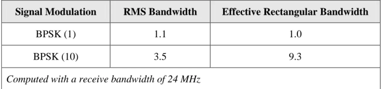
Table 2.3 – Signal Modulation Spectral Characteristics (Betz 2002)... 35
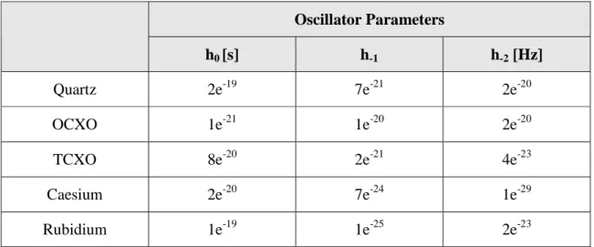
Table 3.1 – Parameters for a Set of Oscillators ... 46
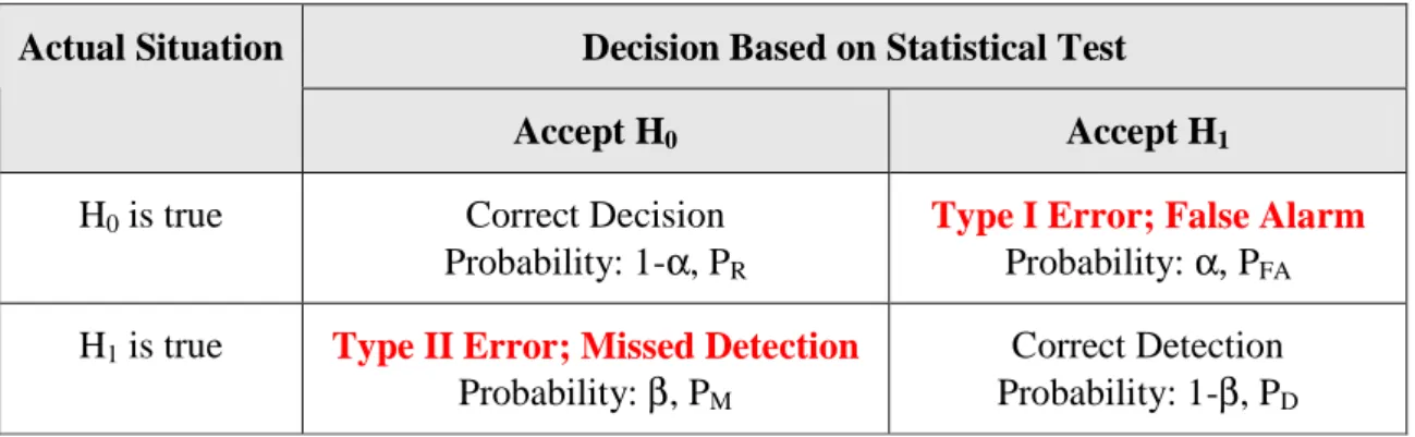
Table 4.1 – Possible Outcomes for Binary Hypothesis Testing ... 79
Table 5.1 – Carrier Tracking Loop Parameters ... 116
Table 6.1 – State Spectral Density... 153
Table 6.2 – Position Error STD ... 165
ix
Figure 2-1 – Example of GPS C/A Code Normalized Auto-Correlation (Left) and
Zoomed-in View About ± 10 chips (Right) ... 18
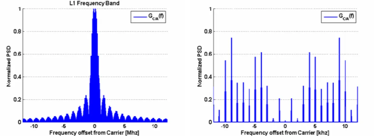
Figure 2-2 – Example of GPS C/A Signal Normalized Power Spectral Density Spectrum (Left) and Zoomed-in View about ± 10 kHz (Right) ... 19
Figure 2-3 – Example of GPS I5 Code (Left) and GPS Q5 Code (Right) Normalized Auto-Correlation ... 26
Figure 2-4 – GPS L5 and C/A Normalized Power Spectral Density Spectrum (Left) and GPS L5, I5 and Q5 Normalized Power Spectral Density Spectrum (Right) ... 26
Figure 3-1 – Allan Standard Deviation for Quartz, TCXO, OCXO, Rubidium and Caesium Oscillators ... 46
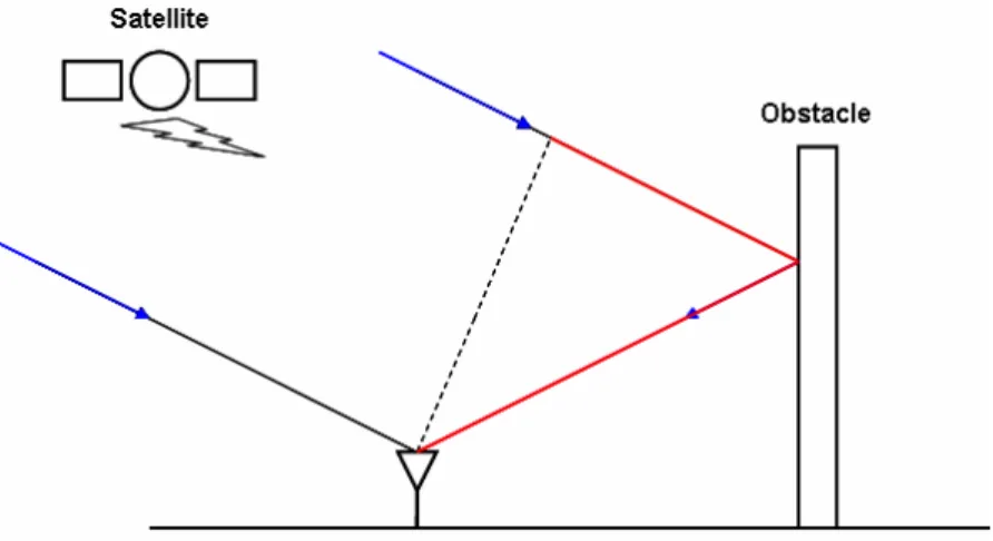
Figure 3-2 – Excess Propagation Length on Non Line-of-Sight (NLOS) Paths... 50
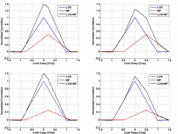
Figure 3-3 – Impact on the Normalized L5 Correlation Function of In-phase Multipaths with 0.2 (Left) and 0.5 (Right) chip delay and for a 6 dB (Top) and 12 dB (Bottom) SMR... 51
Figure 3-4 – Phasor Diagram of Direct, Reflected and Composite Signals ... 52
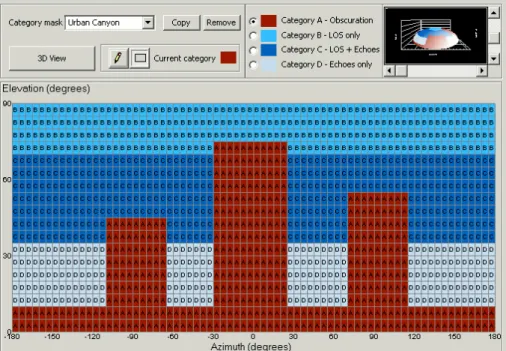
Figure 3-5 – Default Elevation-Azimuth Category Mask Editor for Urban Environments ... 56
Figure 3-6 – Rician Power Probability Envelopes... 57
Figure 3-7 – Data Collection Set-Up ... 58
Figure 3-8 – High level block Diagram of a GPS receiver... 60
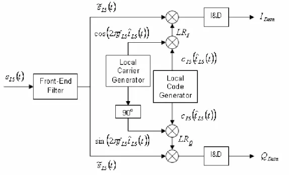
Figure 3-9 - Schematic Representation of I5 Correlation Process... 62
Figure 3-10 – Frequency Power Roll-off Function... 66
Figure 3-11 – Impact of the Frontend Filter Bandwidth on the Shape of the L5 PRN Auto-correlation Function... 67
Figure 3-12 - Symbol Bit Probability Distribution Function... 70
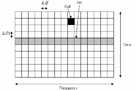
Figure 4-1 – Two-Dimensional GPS Acquisition Search Space ... 78
Figure 4-2 – Generic Acquisition Scheme with Non-Coherent Combining of M Variables Obtained on a Single Code Period (Borio 2007) ... 84
x
Strategies Using 1 ms Coherent Integration ... 92
Figure 4-4 – Probability of Detection versus Total C/N0 in the Presence of Noise and Cross-Correlation (CC) Using 1 ms Coherent Integration and Various Non-Coherent Summation Numbers... 93
Figure 4-5 – Acquisition Sensitivity for Single versus Combined Channel Scenarios .... 95
Figure 4-6 – Correlators’ Output along the Frequency Axis, at the Correct PRN Code Delay ... 97
Figure 4-7 – NH20 Correlation Properties in The Presence of Frequency Errors ... 99
Figure 4-8 – FLL Discriminators Output Using 1 ms Coherent Integration ... 102
Figure 4-9 –Smoothed FLL Detector versus Time for Various C/N0... 105
Figure 4-10 – NH20 Normalized Correlation Function Power in the Presence of Periodic 90o Phase Shifts ... 105
Figure 4-11 – Pilot and Data Correlator Outputs in the Presence of Periodic 90o Phase Shifts ... 106
Figure 5-1 – Generic PLL Architecture ... 110
Figure 5-2 – Mean DP and Coh Discriminator Outputs ... 112
Figure 5-3 – Mean CDP and Cross Discriminator Outputs ... 114
Figure 5-4 – Simulated Equivalent C/N0 Profile for All Simulated Satellites... 117
Figure 5-5 - Histogram of the Dot-Product (Left) and Coherent (Right) Discriminator Outputs for a C/N0 of 36 (Top) and 31 (Bottom) for a Coherent Integration Time of 10 ms... 118
Figure 5-6 - Histogram of the Composite Dot-Product (Left) and Cross (Right) Discriminator Outputs for a C/N0 of 36 (Top) and 31 (Bottom) for a Coherent Integration Time of 10 ms... 120
Figure 5-7 – Frequency Tracking Error in White Noise... 123
Figure 5-8 – Estimated Doppler STD versus C/N0 for Various Carrier Tracking Implementations... 124
Figure 5-9 – Estimated Doppler for the Data (Left) and Pilot (Right) Only Frequency (Top) and Phase (Bottom) Tracking Loop... 125
xi
References and PLL Implementations ... 129
Figure 5-12 - Estimated Three-Dimensional Velocity STD for Static and Kinematic Receivers using Various PLL Implementations ... 130
Figure 5-13 – Schematic DLL Architecture ... 132
Figure 5-14 – Normalized DP discriminator Output Using a One Chip ELS ... 134
Figure 5-15 – Code Tracking Error in White Noise ... 137
Figure 5-16 - Estimated Pseudorange STD versus C/N0 for Various Code Coherent Integration Time... 138
Figure 5-17 – Code Tracking Error Envelope for a 1 chip ELS and Assuming a Single Multipath with an SMR of a 6 (Left) and 12 dB (Right) ... 139
Figure 5-18 – Data/Pilot Coherent Combining... 141
Figure 5-19 - Estimated Pseudorange (Left) and Doppler (Right) STD versus C/N0 for Various Channel Tracking Implementations ... 142
Figure 5-20 - Estimated Doppler for the Data Only, Pilot Only and Data/Pilot Combined Carrier Tracking Loop... 143
Figure 6-1 – Schematic Kalman Filter Based Tracking Loop ... 148
Figure 6-2 - Fourth order Polynomial Approximation of the Filtered L5 Correlation Function ... 150
Figure 6-3 – Estimated Doppler for PRN 15 Using CB and KF Tracking ... 155
Figure 6-4 – Estimated Pseudorange (Left) and Doppler (Right) Error STD using CB and KF Pilot and Combined Tracking Implementations for Various C/N0... 156
Figure 6-5 - Estimated Doppler (Left) and Pseudorange (Right) Error STD using KF Pilot and Combined Tracking for Various C/N0... 157
Figure 6-6 - Estimated Doppler using the Data/Pilot Combined CB and KF Tracking Implementations... 159
Figure 6-7 - Estimated Doppler Error STD for Various External Oscillator References using CB and KF Combined Tracking for various C/N0... 161
Figure 6-8 - Estimated Doppler Error STD obtained by Processing the Rubidium Data Set using Different Clock Parameters in the KF Tracking ... 162
xii
Receivers using CB and KF Tracking Implementations... 163 Figure 6-10 – Horizontal Position Errors using the CB (Left) and KF (Right)
Tracking Implementations ... 165 Figure 6-11 – Three-Dimensional Velocity Errors using the CB Tracking
Implementation ... 166 Figure 6-12 - Three-Dimensional Velocity Errors Using the KF Tracking
xiii Acronyms
ARNS … Aeronautical Radio Navigation Service AWGN … Additive White Gaussian Noise
BER … Bit Error Rate
BOC … Binary Offset Carrier BPSK … Binary Phase Shift Keying
C/A … Coarse Acquisition
CB … Constant Bandwidth
CDP … Composite Dot-Product discriminator C/N0 … Carrier to Noise density ratio
C-NAV … Modernized GPS navigation message format CDMA … Code Division Multiple Access
DC … Deflection Coefficient
DD … Decision Directed discriminator DP … Dot-Product discriminator
DLL … Delay Lock Loop
DS-SS … Direct Sequence Spread Spectrum
ELS … Early-Late Spacing
Eb/N0 … Energy per bit to Noise density ratio
FE … Frontend filter bandwidth FEC … Forward Error Correction FFT … Fast Fourier Transform FLL … Frequency Lock Loop
FTS … Frequency and Time Standard GLONASS … Global Navigation Satellite System GNSS … Global Navigation Satellite System GPS … Global Positioning System
I&D … Integrate and Dump
IF … Intermediate Frequency
I5 … GPS L5 data channel
KF … Kalman Filter
LFSR … Linear Feedback Registers
LOS … Line-Of-Sight
LSA … Least-Squares Adjustment
L1 … L1 frequency band centred at 1575.42 MHz L2 … L2 frequency band centred at 1227.60 MHz
L2C … GPS L2 Civil signal
L5 … L5 frequency band centred at 1176.45 MHz NAV … Legacy GPS navigation message format
NC … Narrow Correlator
xiv NLOS … Non Line-Of-Sight
NP … Neyman-Pearson
NRZ … Non-Return to Zero
PDF … Probability Density Function OCXO … Oven Controlled Crystal Oscillator
P … Precise
PLL … Phase Lock Loop
PVT … Position, Velocity and Time
PRN … Pseudo-Random Noise
PSD … Power Spectrum Density
PSNR … Post-correlation SNR
Q5 … GPS L5 pilot channel
QPSK … Quadrature Phase Shift Keying
RF … Radio Frequency
RMS … Root Mean Square
ROC … Receiver Operating Characteristics RHCP … Right Hand Circularly Polarized
RV … Random Variable RW … Random Walk STD … Standard Deviation SMR … Signal-to-Multipath Ratio SNR … Signal-to-Noise Ratio SV … Space Vehicle SoL … Safety-of-Life
TCXO … Temperature Controlled Crystal Oscillator
XO … Crystal Oscillator
bps … bit per second
sps … symbol per second
Symbols
( )
~•… Quantity
( )
• filtered by the receiver frontend filter( )
•ˆ … Estimate of the quantity( )
•( )
• k … Quantity( )
• at epoch k( )
• +… Quantity
( )
• after a measurement update( )
• −… Quantity
( )
• before a measurement updateA … Signal amplitude
L
xv
2
NH
D … Product of consecutive NH bit sign
d
D … Symbol bit sign
2
d
D … Product of consecutive symbol bit sign
( )•
D … Discriminator of type
( )
•0
D … Decide the signal is absent
1
D … Decide the signal is present
F … Dynamic matrix
G … Shaping matrix
G … Correlation gain
A C
G / … Normalized power density spectrum of the C/A code
5
L
G … Normalized power density spectrum of the L5 PRN code
H … Fourier transform of the frontend filter impulse response
H … Design matrix
0
H … Null hypothesis, the signal is absent
1
H … Alternate hypothesis, the signal is present
H … Design matrix
J … Least-Squares cost function
K … Kalman gain
B
K … Boltzman constant
I
LR … Receiver in-phase local replica
Q
LR … Receiver in-quadrature local replica
f
L … Two-sided pull-in range of the frequency discriminator
φ
L … Two- pull-in range of the phase discriminator
10
NH … NRZ materialization of the HN10 sequence 20
NH … NRZ materialization of the HN20 sequence
NBP … Narrow-band power NP … Normalized power P … Signal power D P … Probability of detection FA
P … Probability of false alarm
M
P … Probability of missed detection
R
P … Probability of correct rejection
K
Q … Marcum Q-function of order K
A C
R / … Normalized auto-correlation function of the C/A code
5
L
R … Normalized auto-correlation function of L5 PRN code
5
~
L
R … Correlation of the local code with the filtered incoming signal
pre
xvi
T … Coherent integration time
T … Test Statistic
R
T … Receiver oscillator time
S
T … Satellite oscillator time
C
T … Spreading code chip duration
R
T … Receiver noise temperature
Sky
T … Sky noise temperature
Sys
T … System noise temperature
W … Weighting function
WBP … Wide-band power
c … NRZ materialization of the spreading code
l
c … Speed of light
d … NRZ materialization of the navigation message
C
f … Spreading code rate
D f … Doppler shift 1 L f … L1 carrier frequency 5 L f … L5 carrier frequency e
f … FLL tracking error variance due to receiver dynamics
h … Frontend filter impulse response
I
n … In-phase correlation noise (assumed Gaussian)
Q
n … In-quadrature correlation noise (assumed Gaussian)
r … Residual vector
t … GPS time
v … Measurement noise vector
x … State vector
z … Observation vector
∆ … Early-Late spacing
Atmo
t
∆ … Delay due to the propagation through the atmosphere
α … Probability of false alarm
β … Probability of missed detection
RMS
β … RMS bandwidth of the signal
rect
β … Effective rectangular bandwidth of the signal
γ … Detection threshold
R
t
δ … Time varying receiver clock bias
S
t
δ … Time varying satellite clock bias
xvii
x
δ … Perturbation of the state vector
z
δ … Misclosure vector
δφ … Estimated carrier phase error
θ … Parameter vector that characterize the received signal
θˆ … Estimate of the parameter vector
e
θ … PLL tracking error variance due to receiver dynamics
λ … Non centrality parameter
φ … Initial carrier phase offset
η … Doppler Dilatation coefficient
υ … Innovation sequence
ρ … True satellite-receiver range
A
σ … Allan standard deviation
LB
σ … Cramer-Rao lower bound tracking standard deviation
( )2•
σ … Variance of the quantity
( )
•τ … Time delay
2
CHAPTER ONE:INTRODUCTION
The Global Positioning System (GPS) was designed to provide position, velocity and timing information to users worldwide, 24 hours a day, regardless of the weather conditions. As a military system, GPS was originally intended to offer civilian users a limited accuracy. This had the effect of initially limiting civilian interest for GPS operations. However, innovative techniques, such as measurement differencing or semi-codeless tracking of the military signals (Lachapelle 2004), gradually improved civilian accuracy and made GPS the main positioning and navigation tool for an increasing number of professional activities (e.g. surveying, ship and aircraft navigation). Simultaneously, miniaturization of electronic components and progress in power management have allowed the integration of GPS chips on autonomous devices such as handheld GPS receivers or cellular phones and have increased its adoption by the general public (e.g. for pedestrian or car navigation). However, this unexpected rise of product development and increasing user demand for location services presents a wide range of challenges, and has highlighted the inherent limitations of the legacy civilian GPS system.
1.1Background
Efforts to overcome the weaknesses of the legacy civilian GPS system and satisfy the increasing demand for higher performance Global Navigation Satellite Systems (GNSSs) have led to the launch of four major global initiatives:
• Restoration and modernization of the Russian GLObal Navigation Satellite
System (GLONASS)
• Development of the European Galileo system • Development of the Chinese Compass system
All four initiatives benefit from the experience gained during the design and exploitation of GPS I and GLONASS. Through innovative design of their respective space and control segments, they all aim at offering enhanced positioning accuracy and reliability as well as improved measurement accuracy, tracking robustness and tracking sensitivity. The focus of these improvements is three-fold: 1) improved satellite availability and/or frequency diversity, 2) increased signal power and 3) signal structure innovations.
Among these initiatives, GPS modernization is of major interest for the GNSS community owing to the emerging availability of GPS Phase II. This modernization was launched under the joint initiative of the U.S. Departments of Defence and Transportation. It began with the introduction of new military and civilian signals to enhance the performance of the legacy GPS system. For the military, the existing P(Y) encrypted signal, transmitted on the L1 and L2 frequencies, is being augmented by a new spectrally split Military signal (M code). The civilian community, on the other hand, is benefiting from the addition of two new civil signals at the L2 and L5 frequencies. The implementation of the L2 civil signal (L2C) started in September 2005 with the successful launch of the first IIR-M satellite. As of February 2008, five such satellites have been placed in orbit and are successfully transmitting L2C; and a full L2C-enabled constellation is expected to be operational by 2010. The L5 signal, broadcast in the protected Aeronautical Radio Navigation Service (ARNS) band centred at 1176.45 MHz,
is intended to support Safety-of-Life (SoL) applications such as aviation navigation. Its implementation was originally scheduled to start with the launch of the next generation of GPS satellites, namely the II-F satellites, in early 2008. However, delays in the IIR-M satellites launch schedule have deferred the first II-F satellite launch to 2009. In the meantime, the U.S. Air Force is having a IIR-M satellite reconfigured to include an L5 demonstration payload. Upon successful review, this IIR-M satellite, planned for launch in June 2008, would temporarily transmit the third civil signal. This, in turn, would provide an on-orbit demonstration capability for the L5 signal and would secure the L5 frequency filing (GPS World 2008). It would also enable the Air Force to conduct some early signal testing prior to any II-F satellite launches.
While it is understood that the major improvement for civilian users will be achieved through direct access (that is, without having to rely on codeless or semi-codeless acquisition and tracking techniques) to signals broadcast at three different frequencies, it is important to bear in mind that the accuracy of the navigation solution will also depend on measurement accuracy. Assuming that ranging biases due to atmospheric and orbital errors can be efficiently mitigated, it can be considered that measurement accuracy is ultimately conditioned by tracking performance. Since GPS signals’ synchronization enables tracking aiding from one frequency to another (Cannon 2004), it is straightforward to understand that the overall positioning accuracy will ultimately be driven by the signal that offers the highest tracking performance. In this regard, both modernized civil signals should benefit from their improved structure (e.g. dataless channel, improved spreading sequence properties or enhanced navigation message format) and should outperform L1 C/A. Furthermore, to ensure its spectral compatibility
with the two military GPS signals broadcast in the same frequency band, many trade-offs were made in designing the L2C signal structure. In particular, the transmitted power and chipping rate had to be set lower for the L2C signal than for its L5 counterpart (Fontana et al 2001). It is therefore anticipated that the L5 signal should offer the highest performance.
In light of the above, it is important to confirm that the key L5 structural innovations do indeed help overcome the inherent weaknesses of the legacy C/A signal in terms of acquisition, tracking and data demodulation. Three innovations in the L5 signal are of central interest for signal performance as they are expected to lead to substantial improvements in tracking sensitivity and measurement accuracy: 1) the presence of a pilot channel broadcast in quadrature from the traditional data bearing channel, 2) the use of new spreading sequences that are broadcast at a higher chipping rate, and 3) the introduction of a Forward Error Correction (FEC) scheme applied to the navigation message. It is expected that the presence of a pilot channel will enhance phase tracking sensitivity and accuracy. Combined with the FEC encoding of the navigation message, this should result in greater data demodulation sensitivity and reliability. Similarly, it is assumed that the increased L5 chipping rate will provide superior noise and multipath mitigation capacities. Additionally, the introduction of secondary codes, referred to as
Neuman-Hofman (NH) codes, will reduce the susceptibility to narrow-band interferences.
However, to fulfill the aforementioned expectations and effectively provide a superior navigation solution, innovative L5 receiver architectures are needed. It is therefore critical to identify any challenge inherent to L5 receiver design, and to confirm, in light of these challenges, the effective performance of the L5 signal.
1.2Limitations of Previous Work
The recent development of GPS software receivers has brought a new perspective to receiver design. Such receivers can provide cost-effective and versatile testbeds for innovative receiver design (e.g. for acquisition or tracking algorithms). They have therefore been extensively used to further improve L1 C/A acquisition and tracking sensitivity (Psiaki & Jung 2002, Shanmugam 2008, Yu 2007). Additionally, in the context of GNSS modernization, they can facilitate research on the performance of the new GNSS signals (Julien 2005, Gernot 2007).
In this perspective, the development of GPS L5 software receivers has, thus far, remained fairly limited. Despite the significant amount of interest initially raised by the L5 signal structure design (Hegarty 1999, Spilker & Van Dierendonck 1999), subsequent research has resulted in limited investigation into the various L5 receiver architectures and their associated performances. In terms of receiver architecture, Ries et al (2002) and Macabiau et al (2003) cover a wide range of L5 receiver functions (e.g. acquisition, tracking, data demodulation and ionospheric correction implementation). They address the data/pilot combining issue for acquisition and tracking; and compare single versus dual frequency ionospheric correction implementations in light of expected L1 and L5 pseudorange accuracy. However, the performance evaluations are mostly theoretical and few simulation results are shown. Further research on L5 receiver architecture has focused mainly on acquisition implementations and, more specifically on L5 secondary codes acquisition and on data/pilot combining. Hegarty & Tran (2003) and Zheng & Lachapelle (2004) proposed acquisition schemes that aim at minimizing the
computational burden while maximizing PRN code detection performance. Yang et al (2004) and Hegarty (2006) discussed optimal ways of re-combining the data and pilot channels’ power in light of both PRN and NH code acquisition. These investigations mostly focused on spreading code acquisition and did not consider the effects of frequency errors. In terms of L5 performance analysis, Bastide (2004) offers the most comprehensive overview. This investigation, however, focuses more on analyzing the degradation of L5 navigation performance in the presence of interference, and is placed in the context of civil aviation requirements. Acquisition, tracking and data demodulation sensitivity thresholds are derived but the receiver architectures under consideration focus on robustness and reliability over accuracy. While ideal for aviation navigation applications, such implementations leave room for significant accuracy improvements. The relative scarcity of research on the L5 signal is probably a consequence of the absence of real field data at the L5 frequency combined with the high cost of hardware simulators. This implies that, to date, most of the L5 software development endeavours have relied on software signal simulators. While software simulators offer numerous advantages (e.g. controllability, repeatability and ease of configuration), they suffer two major drawbacks: 1) integrity and 2) accuracy. When research groups develop software signal simulators to test their software receivers, the integrity of their findings can be threatened by the inter-dependence of their simulation tools and software receivers. Besides, faithfully modelling GNSS signal propagation paths can be very challenging. Specifically, it requires a deep understanding of various GNSS error sources and of the physical processes that create them. In an effort to alleviate the latter problem, research groups tend to use “specialized” L5 software signal simulators. Such tools limit the
number of errors simulated to those relevant to their research. While enabling more faithful simulation, this approach, has mostly limited the extent of previous research to acquisition and tracking, offering little perspective into the measurements and position domains.
Finally, L5 research efforts have remained focused on classical GPS receiver architectures. While it is important to confirm the advantages of the L5 signal modulation in this context, it is important to bear in mind that superior tracking architectures have been proposed to enhance L1 C/A performance. In particular, Kalman filter-based tracking (and acquisition) techniques have been shown to result in significant sensitivity gain over various constant loop bandwidth implementations (Psiaki & Jung 2002, Humphreys et al 2005, Yu et al 2006). While originally introduced for high sensitivity capabilities, later research demonstrated that these techniques could also produce high quality carrier phase measurements (Petovello & Lachapelle 2006). Adapting these techniques to the L5 signal could therefore create the opportunity to further improve L5 tracking and measurement accuracy. Ziedan (2005) uses similar techniques but focuses on very weak signal power and does not compare the results to constant bandwidth tracking techniques.
1.3Objectives and Contribution
The aim of this dissertation is 1) to identify receiver architectures that are most suited to accommodate the major structural innovation inherent to the L5 signal and to maximize its acquisition, tracking and positioning performance and 2) to implement them in a full
GPS L5 software receiver. To reach these objectives, the following research goals have been identified:
1. To understand all the important parameters in the design of an L5 acquisition
algorithm. The focus here is to assess how the secondary codes and the pilot channel
impact the acquisition process; and to find innovative solutions that minimize the computational burden and maximize detection performance.
2. To analyze the L5 constant bandwidth code and carrier tracking performance.
The aim is to confirm that the L5 signal structure improves tracking accuracy. The advantages of pilot-channel tracking and a fast chipping rate are highlighted in terms of carrier tracking sensitivity and code tracking accuracy, respectively.
3. To compare constant bandwidth and Kalman filter-based tracking for L5.
Kalman filter-based tracking has proven to be successful in improving L1 C/A tracking sensitivity and accuracy. Recognizing that the L5 constant bandwidth tracking performance is superior to that of L1 C/A, it becomes critical to verify whether Kalman filter-based tracking can provide further improvements to the L5 tracking sensitivity and accuracy.
4. To use representative simulation and analysis tools with a high degree of fidelity.
It is important to ensure that the results presented are meaningful. In the absence of available real GPS L5 data, it was necessary to use simulation tools. The goal is to obtain two versatile, independent and complementary tools:
a) A Spirent GPS L5 hardware simulator is used in combination with a
b) A full GPS L5 software receiver is developed to confirm, in
post-mission, tracking performance at the measurement and position levels.
In light of these objectives, the major contributions of this thesis can be summarized as follows:
1. Characterization of the benefits and limitations of GPS L5. Such a characterization is
important given the key role of the L5 signal in the overall GPS positioning accuracy. Included in this characterization is a thorough assessment of:
a) L5 acquisition implementation issues and resulting performance
b) L5 tracking performance using constant bandwidth and Kalman filter-based algorithms
2. Confirmation of tracking performance results at the measurement and position levels.
Typically, performance evaluation of the various tracking implementations is conducted at the tracking level. Useful information can be gathered by comparing the impact of various errors on different code and carrier discriminators. However, significant insight can be gained if the impact of these errors can be further propagated. Given this, the various tracking implementations are compared at the measurement and position levels.
3. Use of independent simulation and analysis tools. In the absence of real GPS L5 data,
performance analysis must be conducted using simulation tools such as a signal simulator and a software receiver. To ensure the integrity of the findings presented herein, high-fidelity L5 IF samples obtained from a hardware receiver were used.
1.4Dissertation Outline
This dissertation focuses on the development of a GPS L5 software receiver. In order to provide a comprehensive view of the research realized, the subsequent chapters are structured in the following way.
Chapter 2 reviews the GPS L1 C/A and L5 signal structures. The improvements expected from the latter are presented in light of the weaknesses of the former. Such an evaluation is performed in terms of acquisition, tracking and data demodulation.
Chapter 3 introduces the simulation and analysis tools used throughout this dissertation. The Spirent GSS 7700 hardware is presented with particular emphasis on its error modeling capabilities. The architecture of the L5 software receiver developed in the frame of this research is then outlined. Finally, the derivation of the truth measurements is briefly discussed.
Chapter 4 is an in-depth investigation of the challenges brought by the L5 signal structure in terms of acquisition. The general goal and architecture of a GPS acquisition module are reviewed. The impact of the new L5 spreading sequence and data/pilot implementations are thoroughly discussed and ways of implementing efficient and robust L5 acquisition are proposed and compared.
Chapter 5 is a thorough study of the GPS L5 constant bandwidth tracking loops. The architecture and error sources of the carrier and code tracking loops are presented. The L5 tracking performance is assessed in the presence of noise, oscillator phase noise, multipath and dynamics. The benefits of pilot tracking over data tracking are demonstrated in terms of accuracy, sensitivity and robustness. An innovative correlator level data/pilot combining scheme is proposed and tested.
In Chapter 6, an L5 Kalman filter-based tracking architecture is proposed and evaluated. Its advantages in terms of code and carrier tracking are demonstrated in the presence of noise, oscillator phase noise and dynamics.
Chapter 7 summarizes the major findings of this research and makes recommendations for future work.
CHAPTER TWO:GPS C/A AND L5 SIGNAL STRUCTURES
After a brief review of GPS principles, this chapter presents the structures of two GPS civil signals, namely the Coarse Acquisition (C/A) and L5 signals. It is important to understand that these signals were designed to fulfill very different requirements. The GPS C/A code was a pioneer signal that was designed in the 1970s to facilitate the acquisition of the military signals and that was left freely available to civilian users. The range of applications that rely on it is much wider than anticipated and presents a variety of challenges that had not been forecasted. The C/A signal structure is therefore presented in light of the initial requirements it was meant to fulfill, and its limitations discussed in the context of the challenges it is currently facing. In contrast, the L5 signal was introduced to overcome some weaknesses in the C/A signal and to support Safety-of-Life (SoL) applications such as aviation navigation. The L5 signal structure is therefore described to highlight how it differs from the C/A structure and why it is expected to outperform it in terms of tracking robustness, measurement accuracy and interference protection.
2.1GPS Overview
The fundamental principles of GPS operation are well described in Parkinson (1997a), Misra & Enge (2006) or Kaplan et al (2006). In essence, GPS operates on the principles of measuring the distance between the user and satellites with known location, where the user position can then be retrieved by multi-lateration. Despite the simplicity of this concept, some complexity arises in its implementation since the following key
requirements need to be met: 1) the user must have accurate information about the location of all satellites used in its multi-lateration computations, and 2) the user must be able to accurately estimate its range to each of the satellites in view (i.e. to each of the satellites from which a signal is received).
In GPS, these requirements are fulfilled through careful design of the broadcast signals. The electromagnetic signals broadcast from the satellite in the Radio Frequency (RF) band use a two-layer Direct Sequence Spread Spectrum (DS-SS) modulation technique to carry the GPS data and are based on Code Division Multiple Access (CDMA) principles to distinguish signals coming from different satellites. The first layer of the modulation consists of a sequence of bits that conveys all the information necessary for precise positioning (e.g. satellites location or ionospheric corrections), and is referred to as the navigation message. The second layer consists of a repeating pseudo-random sequence of bits that spread the signal across a wide bandwidth and is therefore referred to as the spreading code. The purpose of the spreading code is two-fold: 1) to allow determination of the signal propagation time or, equivalently, the distance between the receiver and the satellite, and 2) to spread the signal across a wide bandwidth and therefore provide a satisfactory level of tolerance against intentional or unintentional interference (including other GNSS signals).
In GPS I, three signals were designed to meet the aforementioned specifications. Two high-performance signals were designed for military users, and one lower performance signal was left available to civilian users. The military signals, broadcast in the L1 (1575.42 MHz) and L2 (1127.60 MHz) frequency bands, use long spreading codes and high chipping rates. These codes, referred to as Precise (P) spreading codes, are further
encrypted by a classified code to form secure versions of the published P codes. The resulting precise encrypted codes, referred to as P(Y) codes, are therefore restricted to authorized users. The third signal, transmitted on the L1 frequency only, was mainly intended to facilitate the acquisition of the two military signals (hence its name, C/A for
Coarse Acquisition). To this end, the spreading code it uses is much shorter and has a
slower chipping rate than the precise encrypted P(Y) spreading codes. Since all the GPS signals broadcast by one satellite are synchronized, military users can use the timing information provided by the C/A signal to lock onto both precise military signals. While shorter spreading codes and slower chipping rates can make acquisition faster, they also provide lower tracking accuracy and reliability. Consequently, the accuracy available to most civilian users is limited by the shortcomings of the C/A signal in terms of tracking accuracy, sensitivity and reliability.
In GPS II, four additional signals are being introduced: two new military signals broadcast in the L1 and L2 frequency bands, and two new civilian signals transmitted on the L2 and L5 (1176.45 MHz) frequencies. Designed to meet the same fundamental system requirements, these signals are also expected to increase the accuracy available to both military and civil users. From a civilian perspective, the advantage of broadcasting civil signals at the L2 and L5 frequencies is two-fold. First it brings the advantages of frequency diversity to civilian users. This, in turns, greatly enhances the civilian system reliability (to counter possible jamming in individual frequency bands) and ionospheric mitigation capabilities (since ionosphere is a dispersive medium, as will be explained in chapter 3). Second, these signals exhibit key structural innovations that improve measurement accuracy, tracking sensitivity and tracking robustness. In particular, the L5
signal, intended to support SoL applications, is expected to offer the highest accuracy amongst GPS civil signals. More specifically, the L5 signal was designed to provide the following (Spilker & Van Dierendonck 2001): enhanced cross-correlation side-peaks protection, improved narrow-band interference mitigation, instantaneous carrier phase ambiguity resolution for cm-level positioning, and improved multipath performance. Furthermore, and contrary to the high-performance military signals, the L5 signal was designed to enable direct code acquisition without the C/A code.
Despite its inherent limitations, the GPS C/A signal has shaped the field of satellite navigation. Similarly, thanks to its high-accuracy profile, the GPS L5 has the potential to revolutionize the scope of civilian GPS operations. A summary of the GPS L1 C/A and L5 signals’ characteristics are given in and a thorough description of their structure is given in the following sections.
2.2C/A Signal Structure
The C/A signal is Right Hand Circularly Polarized (RHCP) and use a Binary Phase Shift
Keying (BPSK) modulation. As mentioned previously, the L1 carrier is modulated by a
navigation message and a spreading code. These sequences both use rectangular
Non-Return to Zero (NRZ) materialization. The L1 frequency is centred at 1575.42 MHz,
resulting in a wavelength of approximately 19 cm.
The navigation message contains information relevant to precise positioning (Spilker 1997a). In particular, it includes: 1) a set of precise orbital parameters, called ephemeris parameters, from which the current position, velocity and clock error of the satellite can be derived, 2) a set of coarser orbital parameters, called almanac parameters, from which
the location of all the GPS satellites can be approximated over a period of 14 days, and 3) a set of ionospheric correction parameters, that can be used by single frequency users to remove (on average) about 50% of the ranging error due to signal propagation through the ionosphere (Klobuchar 1997).
Table 2.1 - GPS C/A and L5 Signals Characteristics
GPS L5 Properties GPS L1 C/A
I5 Q5
Frequency [MHz] 1176.45 1575.42 1575.42 Transmitted Power [dBW] - 157 - 154 - 154
Code Length [Chips] 1023 10230 10230 Code Chipping Rate [Mcps] 1.023 10.23 10.23
Modulation BPSK QPSK
Navigation Data Yes Yes No
Data Rate [sps] 50 50 -
Data Encoding No FEC (7, 1/2) -
Secondary Code No Yes Yes
Secondary Code Length
[Chips] - 10 20
The navigation message repeats every 12.5 min and has a data rate of 50 Hz. This relatively low data rate was selected to enable low Bit Error Rates (BER) for common
To spread the signal over a wide frequency, the C/A signal uses 1023-bit PRN codes broadcast with a 1.023 MHz chipping rate; the C/A spreading codes repetition period is therefore one millisecond. These spreading codes are part of the 1023-bit Gold code family described in Gold (1967) and Spilker (1997b). They are obtained as the modulo-2 addition of two maximum length sequences generated by two Linear Feedback Registers (LFSR) of 10 stages each. Maximum length sequences offer better auto-correlation side peaks protection than Gold codes; the latter were however selected for the superior cross-correlation (with code from other satellites) side peaks protection they offer. The degradation they suffer in terms of auto-correlation side-peaks protection is minimal since the Gold codes provide, in the absence of any Doppler effects, a minimum auto- and cross-correlation side peaks isolation of 23.9 dB.
Figure 2-1 shows the normalized auto-correlation plot for PRN 23 C/A code materialization. It can be seen that the main auto-correlation peak is a perfect triangle. In fact, in the context of tracking, it is common to neglect the auto-correlation side peaks and therefore to model the auto-correlation function as
( )
> ≤ − = chip x if chip x if x x RC A 1 0 1 1 / (2-1)where RC/Ais the normalized auto-correlation function of the C/A spreading code materialization.
This approximation, however, cannot be made in the context of signal acquisition, where auto- or cross-correlation side-peaks must be taken into account.
Figure 2-1 – Example of GPS C/A Code Normalized Auto-Correlation (Left) and Zoomed-in View About ± 10 chips (Right)
Since the Power Spectral Density (PSD) and the auto-correlation of a wide-sense stationary signal form a Fourier pair (Brown & Hwang 1992), the PSD of the C/A signal can be obtained by applying a Fourier transform to its auto-correlation function. As demonstrated by Macabiau (2003), and confirmed by Figure 2-2, the resulting PSD is a peak spectrum that can be approximated by its sinc envelope. The spectral lines result from the spreading sequence periodicity and are separated by an increment of 1 kHz (since the PRN code has a repetition period of 1 ms). The sinc shape corresponds to the PSD of the rectangular materialization used for the spreading code chips. Finally, the normalized PSD of the GPS C/A signal can be approximated as
( )
2 / sin = C C C A C f f f f T f G π π (2-2)where GC/A is the normalized PSD of the C/A spreading code, and TC =1 fC is the C/A spreading code chip duration.
The C/A signal is broadcast with a minimum specified received power of -158.5 dBW when using a 0 dBic antenna RHCP (ICD-GPS-200D). This very low signal power, combined with the spreading of the navigation message over a very large bandwidth brings the signal PSD under the thermal noise floor and effectively limits interferences between GPS and other existing communications systems.
Figure 2-2 – Example of GPS C/A Signal Normalized Power Spectral Density Spectrum (Left) and Zoomed-in View about ± 10 kHz (Right)
Finally, considering all the above and taking the propagation time into account, the C/A signal received from a particular satellite can be modeled, at the receiver antenna, as
( )
t P( )
t d(
t( )
t)
c(
t( )
t)
(
f t( )
t) ( )
ntsC/A = 2 C/A C/A C/A C/A cos 2π L1 C/A +φC/A + (2-3)
where PC /A
( )
t is the instantaneous power of the received C/A signal, and( )
2( )
2/
/ t A t
PC A = C A , withAC /A
( )
t the instantaneous amplitude of the signal, d( )
t is the NRZ materialization of the navigation data bit, cC /A( )
t is the NRZ materialization of theis the noise on the received signal, and tC /A
( )
t is a function incorporating the effects ofpropagation delay and Doppler shift on the received C/A signal.
In the framework of this dissertation, the noise is assumed to be a zero-mean Additive
White Gaussian Noise (AWGN) process. In reality, the noise is neither white nor
Gaussian. The Gaussian assumption, however, is justified by the central limit theorem (Walpole et al 1998), and is found to work well in practice. Similarly, the noise bandwidth limitation due to frontend filtering and the correlation introduced in consecutive noise samples by the sampling processes are ignored. However, the whiteness approximation was found to work well in practice. Under normal conditions, the L1 C/A thermal noise floor, which is based on the Boltzman constant and the system temperature, can be approximated at about -205 dBW/Hz (Van Dierendonck 1997). In general, tC /A
( )
t is an arbitrary function of t , where t denotes the GPS time, that depends on the conditions encountered by the signal on its propagation path between the satellite and the user; a simple first order approximation can however be given by (O’Driscoll 2007)( ) (
)
C A AC t t
t / = 1+η −τ / (2-4)
where ηis the time dilation coefficient due to the Doppler effect and τC /A is the time
delay introduced on the L1 C/A signal during the satellite-receiver propagation time. The Doppler effect is a time contraction (or dilatation) due to the relative satellite-user motion along the propagation path of the radio wave and can be expressed as (Axelrad & Brown 1997)
u c v vSat Rx ⋅ − = η (2-5)
where vSat,v are the velocity vectors for the satellite and receiver respectively, c is the Rx
speed of light, u is unit vector along the Line Of Sight (LOS) between the satellite and the receiver, and x⋅y is the dot-product of the vector x and y .
Thus, if two events are separated by T seconds in the transmitted signal, they will be separated by T×
(
1+η)
seconds when the signal reaches the receiver. This effect is commonly associated with the frequency shift it creates on the signal carrier(
)
(
2 fL1 1+ t)
=cos(
2(
fL1+ fD)
t)
cos π η π (2-6)
where fD =ηfL1 is known as the Doppler shift.
However, it is important to note that this effect impacts all components of the transmitted signal. Therefore the signal effectively suffers two additional Doppler effects: one on the navigation message (data Doppler) and one on the spreading code (code Doppler). The time delay can be expressed as
Atmo A C l A C t c / , / = +∆ ρ τ (2-7)
where ρ is the true distance between the satellite and the receiver, c is the speed of l
light, and ∆tC/A,Atmo is the delay due to propagation of the radio wave through the atmosphere. From a GPS standpoint, the atmosphere reduces to two layers: the ionosphere and the troposphere. Their respective effects on radio wave propagation will be further discussed in Chapter 3.
Now that the C/A signal structure has been reviewed, it is instructive to look at the L5 signal structure to understand how it is expected to outperform the C/A signal.
2.3GPS L5 Signal Structure
The L5 signal is broadcast using a Quadrature Phase Shift Keying (QPSK) modulation with a minimum specified received power of -154.9 dBW (IS-GPS-705). The L5 frequency is centred at 1176.45 MHz, resulting in a wavelength of approximately 25 cm. The L5 signal is composed of two channels: 1) a data channel (I5) that carries the navigation message, and 2) a pilot channel (Q5) that does not possess a navigation message. The I5 and Q5 channels are synchronized and orthogonal. In addition, they equally share the total L5 signal power. Consequently, taken separately, I5 and Q5 will have a minimum received power 0.6 dB higher than currently specified for the GPS C/A signal.
The presence of a dataless channel, broadcast in quadrature from the conventional data channel, allows significant phase tracking sensitivity, accuracy and robustness gain. The absence of unknown data bit transitions on the Q5 channel enables the use of pure Phase Lock Loop (PLL) discriminators (instead of the traditional Costas discriminator used for data bearing channel such as GPS L2-P(Y) or GPS L1-C/A) that possess wider linear tracking ranges and were shown (e.g. Julien 2005) to improve the phase tracking sensitivity, to remove the risk of half cycle slips and to reduce that of full cycle slips. It also allows the use of longer coherent integration times which can enhance thermal noise mitigation on the correlator output values and improve tracking accuracy. Longer coherent integrations also play a critical role in the re-acquisition of weak signals.
Another consequence of this channel separation is that several implementations can be envisioned for the acquisition and tracking of the L5 signals since some trade-offs must be made in terms of complexity, computational burden, accuracy and reliability.
The L5 data bit rate has been set to 50 bits per second (bps). However, to compensate for the fact that the QPSK modulation induces a 3 dB degradation in the energy allocated for the transmission of the navigation data bit, the original navigation data bit stream is coded with a rate- 21 ,K =7 Forward Error Correction (FEC) convolutional code. The effect of this encoding is to offer more reliable recovery of the data bit train. Spilker (1977) demonstrated that a receiver using soft decision Viterbi decoding can decode, with the same error rate, a 50 bps data stream and its corresponding FEC (12,7) encoded stream transmitted with 5 dB less signal-to-noise ratio. Another consequence of this encoding is that the data channel will have to effectively transmit the encoded symbols at 100 symbols per second (sps) to maintain an effective navigation message rate at 50 bps. Besides, the C-NAV navigation message format used for the L5 signal differs from the NAV navigation message format used for the C/A signals. In particular, the rigid frame and superframe sequencing order adopted for the NAV message (Spilker 1997a) is replaced by a more flexible sequencing scheme where the control segment can modify the L5 subframe broadcasting order as it sees fit. The C-NAV message also includes new ephemeris parameters that improve the accuracy of the satellite position determination. The PRN codes used on each channel are 10230 chips long and are broadcast with a 10.23 MHz chipping rate; the L5 PRN codes repetition period is therefore one millisecond. These codes are generated from two different maximum length sequence generators, XA and XBi, of 13 stages each. XA generates a truncated sequence of 8190
chips and XBi a sequence of 8191 chips. Both sequences are modulo-2 added to generate
the 10230-chip PRN codes. Note that, due to their desired length, the L5 PRN codes are not Gold Codes. As such, their auto- and cross-correlation properties are not optimal. However, owing to their increased length, and to a careful selection of initial stages, they provide a minimum isolation 2.5 dB better than the current GPS C/A code, as illustrated in Table 2.2.
Table 2.2 - GPS L5 Code Isolation Properties (Ries et al 2002)
Minimum Side Peaks Protection [dB]
Minimum Cross-Correlation Peaks Correction [dB]
R(I,I) R(Q,Q) C(I) C(Q) C(I,Q)
Without NH code
-29.2 -29.0 -26.4 -26.5 -62.1
With NH code
-29.8 -29.4 -28.1 -28.5 -33.3
R(I,I) = auto-correlation of all I5 codes, R(Q,Q)= auto-correlation of all Q5 codes, C(I)= cross-correlation of all I5 codes vs. all I5 and Q5 codes, C(Q)= cross-correlation of all Q5 codes vs. all I5 and Q5 codes, C(I,Q) = cross-correlation of (I,Q) pair.
The I5 and Q5 channels are further modulated by Neuman-Hofman (NH) codes. The NH-modulated PRN codes are referred to as tiered sequences. For the I5 component, the PRN code is further modulated by a 10-bit NH sequence (NH10 = 0000110101). For the Q5
component, the PRN code is further modulated by a 20-bit NH sequence (NH20 = 00000100110101001110). Each bit of the NH codes is 1 ms, and the NH bit
tiered sequences on the data and pilot channel respectively. Besides, the NH10 and NH20
sequences are fully synchronized with the 10 ms symbol bit and the 20 ms data bit respectively.
Figure 2-3 shows the normalized tiered sequence auto-correlation plot for PRN 23 on the L5 data and pilot channels. It is interesting to note that the NH codes create several secondary peaks on the tiered sequence auto-correlation. As underlined in Ries et al (2002) and Macabiau et al (2003), these peaks create a risk for biased acquisition. This issue will be addressed in detail in Chapter 4.
As for the C/A signal, the L5 signal PSD is a peak spectrum that can be approximated by its sinc envelope. Since the tiered sequences have repetition periods of 10 and 20 ms, the code spectral line separation is reduced from 1 kHz to 100 Hz and 50 Hz on the data and pilot channel, respectively. Besides, since the L5 spreading code chips are broadcast at a 10.23 MHz chipping rate, the main lobe of the sinc envelope is increased from approximately 2 MHz to 20 MHz, as shown in Figure 2-4. The normalized PSD of the GPS L5 signal can therefore be approximated as
( )
2 5 sin = C C C L f f f f T f G π π (2-8)where GL5 is the normalized PSD of the L5 spreading code, and TC =1 fC is the L5 spreading code chip duration.
Figure 2-3 – Example of GPS I5 Code (Left) and GPS Q5 Code (Right) Normalized Auto-Correlation
The purpose of the NH sequences is three-fold. First, due to their periodicity, they narrow the code spectral line separation from 1 kHz to 100 Hz and 50 Hz on the data and pilot channels respectively. As illustrated in Figure 2-4, it has the effect of reducing the power carried in each spectral line and therefore, to enhance the L5 signal inherent mitigation capacities against narrow-band interference.
Figure 2-4 – GPS L5 and C/A Normalized Power Spectral Density Spectrum (Left) and GPS L5, I5 and Q5 Normalized Power Spectral Density Spectrum (Right)
As shown in Table 2.2, the NH codes also improve the cross-correlation properties amongst spreading codes. Finally, as they are aligned with the navigation data and symbol bits, data synchronization can be performed by correlating the received NH sequences with the locally generated ones. This method provides better reliability compared to classical techniques such as the histogram process (van Dierendonck 1997). From the above, and taking the propagation time into account, the L5 signal received from a particular satellite at the receiver antenna can be represented as
( )
( )
(
( )
)
(
(
( )
)
( )
)
(
(
( )
)
( )
)
(
(
( )
( )
)
)
n( )
t t t f t t c t t NH t t f t t c t t NH t t d t P t s L L L L Q L L L L L I L L L L + + + + = 5 5 5 5 5 5 20 5 5 5 5 5 5 10 5 5 5 2 sin 2 cos φ π φ π (2-9)where PL5
( )
t is the instantaneous power of the received L5 signal, d( )
t is the NRZ materialization of the navigation data bit, cI 5( )
t and cQ5( )
t are the NRZ materializationsof the L5 PRN codes on the data and pilot channels respectively, NH10
( )
t and NH20( )
tare the NRZ materializations of the L5 NH codes on the data and pilot channels respectively, fL5 is the L5 frequency, φL5 is the initial carrier phase offset, n
( )
t is the noise on the received signal, and tL5( )
t is a function incorporating the effects ofpropagation delay and Doppler shift on the received L5 signal.
The noise is again assumed to be a zero-mean AWGN process. However, to account for the larger filter insertion loss expected due to more stringent filtering requirements, a larger L5 noise figure has been suggested by Hegarty (2006). The -200 dBW/Hz noise floor value he proposed has been widely accepted and is therefore used herein.
In general, tL5