A Robust, Reliable and Deployable Framework for In-vehicle
Security
by
Azeem Hafeez
A dissertation submitted in partial fulfillment
of the requirements for the degree of
Doctor of Philosophy
(Electrical and Computer Engineering)
in the University of Michigan-Dearborn
2020
Doctoral Committee:
Professor Selim Awad
Assistant Professor Anys Bacha Professor Hafiz Malik, Chair Professor Adnan Shaout
© Azeem Hafeez 2020 All Rights Reserved ORCID iD 0000-0001-8855-6158
ACKNOWLEDGEMENTS
All is well that ends well, and since every beginning has an ending, my Ph.D. research ended in this semester i.e. Winter 2020, and it ended well. Special thanks to my amazing Ph.D. Supervisor, Sir Hafiz Malik, it could have never been possible without his guidance, assistance and all-time available help. Thanks to the people who made this dissertation possible, I would like to pay special thanks to Professor Paul Richardson who was a source of motivation for me throughout my degree, I don’t have words to thank Professor Paul. I will also like to thank my colleagues from ECE office, Mariann Brevoort, Jesse Cross, Amanda Donovan and Michael Hicks who always supported me and celebrated my success as a family. I would also like to thank especially my family, my friends, my grandfather (Mohammad Baksh Multani) who motivated me to do Ph.D., my dissertation committee members, my father (Hafeez Ur Rehman) who always believed in me that I can achieve this goal, my uncle (Ashraf Chaudry) who encouraged me during my high school studies, my wife (Shangraf Malik) who provided me her full support during my graduate studies. Last but not least, I like to dedicate this to my two lovely sons Ibraheem and Moosa who provided me determination to achieve this goal.
TABLE OF CONTENTS
DEDICATION . . . ii
ACKNOWLEDGEMENTS . . . iii
LIST OF FIGURES . . . vii
LIST OF TABLES . . . ix LIST OF ABBREVIATIONS . . . x ABSTRACT . . . xiii CHAPTER I. Introduction . . . 1 1.1 Motivation . . . 1 1.1.1 Device-specific Distortion . . . 4 1.1.2 Channel-specific Distortion . . . 4 1.2 Research Objectives . . . 4
1.2.1 ECU and Pin Level Uniqueness . . . 4
1.2.2 Channel Level Uniqueness . . . 5
1.3 Contributions . . . 5
1.4 Threat Model . . . 6
1.5 Dissertation Outline . . . 8
II. Overview of CAN, FlexRay and LIN Protocol . . . 10
2.1 CAN- an Overview . . . 12
2.2 FlexRay- an Overview . . . 16
2.3 LIN- an Overview . . . 19
2.4 Comparison of CAN, FlexRay and LIN Protocol . . . 22
2.4.1 CAN vs. FlexRay . . . 22
2.4.2 LIN vs. CAN . . . 24
III. Related Work. . . 30
3.1 Parametric Monitoring based IDS . . . 32
3.2 Information Theory-based IDS . . . 33
3.3 Machine Learning-based IDS . . . 33
3.4 Fingerprinting-based IDS . . . 34
3.4.1 Scission . . . 35
3.4.2 Using Inimitable Characteristics of Signals . . . 36
3.4.3 VoltageIDS . . . 37
3.4.4 Clock based Intrusion Detection System (CIDS) . . 40
3.4.5 Viden . . . 44
3.4.6 Implementing In-Vehicle Security Using Higher Or-der Statistics . . . 44
IV. Study of ECU Specific Distortion and ECU Identification by Using Neural Networks . . . 47
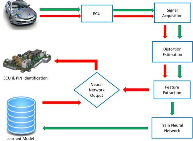
4.1 Introduction . . . 47 4.1.1 Research Objectives . . . 48 4.2 System Model . . . 49 4.2.1 Signal Acquisition . . . 50 4.2.2 Distortion Extraction . . . 51 4.2.3 Density Estimation . . . 55
4.2.4 ANN based Model Learning . . . 56
4.3 Experiments and Results . . . 58
4.3.1 Experimental Setup . . . 58
4.3.2 Dataset Description . . . 59
4.3.3 Performance Evaluation Measures . . . 59
4.3.4 Feature Stability . . . 61
4.3.5 ECU-Level Identification . . . 62
4.3.6 Pin-Level Identification . . . 64
4.3.7 Comparison Against State-of-the-art . . . 66
V. Control System Parameters Based Transmitter Identification 68 5.1 Introduction . . . 68
5.2 System and Mathematical Modelling . . . 71
5.2.1 Channel Modeling . . . 72
5.2.2 Signal Acquisition . . . 73
5.2.3 Step Response Acquisition . . . 74
5.2.4 Feature Extraction . . . 79
5.2.5 Training Neural Network . . . 83
5.3 Experimental Setup, Dataset and Results . . . 84
5.3.2 Dataset Description . . . 84
5.3.3 Performance Evaluation Measures . . . 85
5.3.4 Experimental Results and Analysis . . . 86
VI. Channel Specific Distortion Based Transmitter Identification Using Neural Networks . . . 89
6.1 Introduction . . . 89
6.2 Proposed System Model and Channel Distortion Modeling . . 92
6.3 Non-parametric Density Estimation . . . 94
6.3.1 Channel Identification . . . 96
6.4 Experimental Setup, Results and Analysis . . . 97
6.4.1 Experimental Setup . . . 97
6.4.2 Dataset Description . . . 99
6.4.3 Experimental Results and Analysis . . . 99
VII. Statistical Parameters Based Transmitter Identification . . . 102
7.1 Introduction . . . 102 7.2 System Model . . . 105 7.2.1 Signal Acquisition . . . 107 7.2.2 Distortion Extraction . . . 108 7.2.3 Histogram Computation . . . 111 7.2.4 Density Estimation . . . 113
7.2.5 Adaptive Channel Specific Clustering Approach . . 117
7.3 Experimental Results and Analysis . . . 120
7.3.1 Experimental Setup . . . 120
7.3.2 Dataset Description . . . 122
7.3.3 Performance Evaluation Measures . . . 122
7.3.4 Performance Analysis . . . 124
7.3.5 Comparison Against State-of-the-art . . . 126
VIII. Conclusion and Future Work . . . 129
LIST OF FIGURES
Figure
1.1 Threat model for in-vehicle communication . . . 7
1.2 Attack detection for in-vehicle communication . . . 8
2.1 CAN signalling mode . . . 13
2.2 Arbitration field operation in CAN . . . 14
2.3 Data frame of CAN . . . 14
2.4 Remote frame of CAN . . . 16
2.5 Error frame of CAN . . . 16
2.6 Overload frame of CAN . . . 16
2.7 Frame bit stuffing of CAN . . . 16
2.8 FlexRay hybrid topology . . . 18
3.1 Existing SOA approaches for IVN attacks . . . 30
3.2 Intrusion detection based approaches . . . 32
3.3 VoltageIDS steps . . . 38
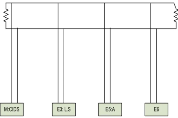
3.4 Block diagram of the CAN realization used for experiments . . . 42
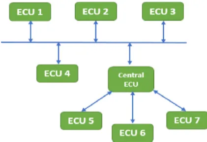
4.1 Generalized architecture of CAN . . . 48
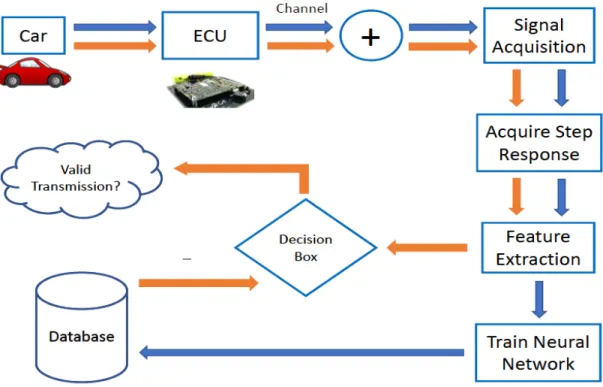
4.2 Block diagram of transmitter identification system . . . 50
4.3 Screenshots of the actual and expected waveforms . . . 52
4.4 Distortion in the ECU signal . . . 53
4.5 Ideal voltage levels for CAN . . . 55
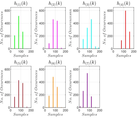
4.6 Histograms ofd(i)(n) for ECU E(1)-E(7) . . . 55
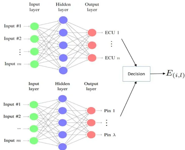
4.7 Merged neural network structure . . . 57
4.8 Density approximation of distortion . . . 60
4.9 Effectiveness of feature-set . . . 61
4.10 Estimated distortion distributions for all 7 ECUs . . . 62
4.11 Bar graph of PM for ECU classifier . . . 64
4.12 ROC of E(i) . . . 64
4.13 Bar graph of PM for pin classifier . . . 66
4.14 ROC of pin classifier . . . 66
5.1 Channel specific step response . . . 71
5.2 Block diagram of transmitter identification system . . . 71
5.3 Message authentication by E(F P) . . . 72
5.5 ECU’s digitally sampled pulse train . . . 75
5.6 Moving average pulse train . . . 75
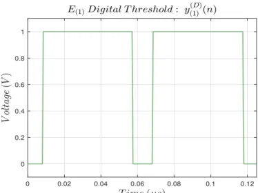
5.7 Digitally threshold pulse train . . . 76
5.8 Rising and falling edges of pulse train . . . 77
5.9 Abnormally short pulse . . . 78
5.10 Abnormally long pulse . . . 78
5.11 Single pulse . . . 79
5.12 Artificial neural network architecture . . . 83
5.13 Bar graph of PM for channel classifier . . . 86
5.14 Receiver operating characteristic curve . . . 88
6.1 Channel-specific distortion in the CAN signal . . . 90
6.2 Block diagram of the proposed system . . . 91
6.3 Lumped element model for CAN . . . 93
6.4 Architecture of sub-networks with gateways . . . 95
6.5 Distortion distribution and estimated density function . . . 96
6.6 Training and test phases for intrusion detection system . . . 98
6.7 Estimated distortion density comparison . . . 100
7.1 Comparison of expected and actual signal . . . 106
7.2 Block diagram of the system model . . . 107
7.3 Distortion in the signal . . . 109
7.4 Lumped element model . . . 109
7.5 Histogram ofx(j)(n) for C(j) . . . 111
7.6 Approximation of various PDFs from histogram . . . 112
7.7 Estimating density function . . . 113
7.8 P-P plot . . . 113
7.9 Scatter plot of α vs β forC(j) . . . 115
7.10 Distribution functions of α and β . . . 116
7.11 3-D plot of joint density function for single channel . . . 118
7.12 Comparison of estimated distortion density for C(j) . . . 121
7.13 Comparison of joint density functions . . . 122
LIST OF TABLES
Table
2.1 CAN vs. FlexRay . . . 24
2.2 LIN vs.CAN . . . 26
2.3 LIN vs. FlexRay . . . 27
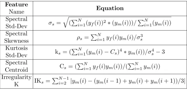
3.1 Time domain feature-set . . . 36
3.2 Frequency domain feature-set . . . 37
3.3 Comparison of fingerprinting methods . . . 39
3.4 Message IDs and the period . . . 41
4.1 Summary of neural network structure . . . 58
4.2 Confusion matrix for ECU classifier . . . 63
4.3 Performance matrix of ECU classifier . . . 63
4.4 Confusion matrix for pin classification . . . 65
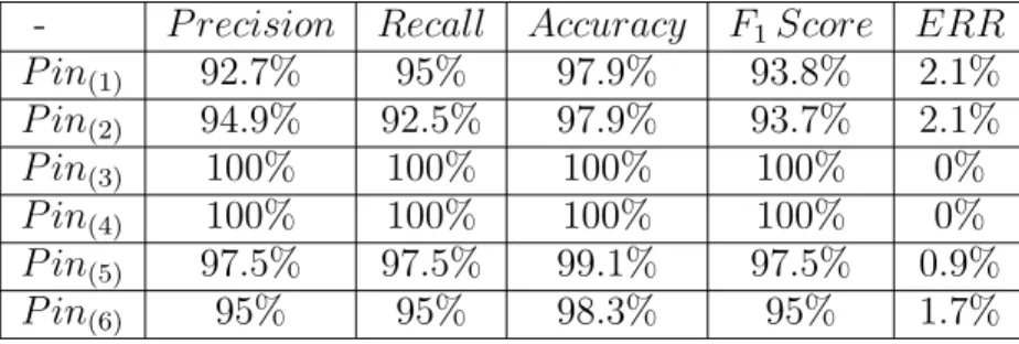
4.5 Performance matrix of pin classification . . . 65
4.6 Comparison with other methods . . . 67
5.1 Technical specifications of channels . . . 84
5.2 Confusion matrix for transmitter classifier . . . 85
5.3 Performance matrix of ECU classifier . . . 87
6.1 Technical specifications of channels . . . 98
6.2 Confusion matrix for channel classifier . . . 99
7.1 Technical specifications of channels . . . 120
7.2 Confusion matrix for channel classifier . . . 124
7.3 Performance matrix of channel classifier . . . 126
LIST OF ABBREVIATIONS
AI artificial intelligence
ANN artificial neural network
CAN controller area network
CANL CAN Low
CANH CAN High
CIDS clock based intrusion detection system
CPS cyber-physical system
CRC cyclic redundancy code
DAC digital to analog converter
CIDS clock based intrusion detection system
DIDS distortion based intrusion detection system
ECUs electronic control units
EMI electromagnetic interference
FIR finite impulse response
FN false negative
FP false positive
HMI human machine interface
IDS intrusion detection system
IVNs in-vehicle networks
LEM lumped element model
LIN local interconnect network
ML machine learning
MOST media oriented system transport
PDF probability density function
QoS Quality of Service
ROC receiver operating characteristic
SOA state Of-the-art
TN true negative
ABSTRACT
Cyber attacks on financial and government institutions, critical infrastructure, vot-ing systems, businesses, modern vehicles, etc., are on the rise. Fully connected au-tonomous vehicles are more vulnerable than ever to hacking and data theft. This is due to the fact that the protocols used for in-vehicle communication i.e. controller area network (CAN), FlexRay, local interconnect network (LIN), etc., lack basic se-curity features such as message authentication, which makes it vulnerable to a wide range of attacks including spoofing attacks. This research presents methods to pro-tect the vehicle against spoofing attacks. The proposed methods exploit uniqueness in the electronic control unit electronic control unit (ECU) and the physical chan-nel between transmitting and destination nodes for linking the received packet to the source. Impurities in the digital device, physical channel, imperfections in design, ma-terial, and length of the channel contribute to the uniqueness of artifacts. I propose novel techniques for electronic control unit (ECU) identification in this research to address security vulnerabilities of the in-vehicle communication. The reliable ECU-identification has the potential to prevent spoofing attacks launched over the CAN due to the inconsideration of the message authentication. In this regard, my techniques models the ECU-specific random distortion caused by the imperfections in digital-to-analog converter digital to digital-to-analog converter (DAC), and semiconductor impurities in the transmitting ECU for fingerprinting. I also model the channel-specific random distortion, impurities in the physical channel, imperfections in design, material, and length of the channel are contributing factors behind physically unclonable artifacts. The lumped element model is used to characterize channel-specific distortions. This
research exploits the distortion of the device (ECU) and distortion due to the channel to identify the transmitter and hence authenticate the transmitter.
CHAPTER I
Introduction
The main objective of this chapter is to provide the introduction of the disserta-tion. Section 1.1 provides the motivation to implement security in modern electric vehicle, which is followed by the research objectives in section 1.2. Original contribu-tions of this research are reported in section 1.3. Threat model is presented in section 1.4. Finally the complete outline of dissertation is provided in section 1.5.
1.1
Motivation
The modern vehicle is a cyber-physical system (CPS) equipped with many wire-less and wired communication interfaces and a large number of microcontrollers and electronic control units (ECUs) networked via various in-vehicle networks (IVNs) (1; 2; 3; 4; 5; 6; 7; 8), such as CAN (8), LIN (1), media oriented system trans-port (MOST) (2), FlexRay (3), etc., that connect safety-critical components of the vehicle, including brakes, airbags, engine control, and active safety devices, e.g., elec-tronic stability program, adaptive cruise control, and so on. Integration of wireless interfaces, e.g., Bluetooth, Wi-Fi, etc., with IVNs and use of the legacy CAN pro-tocol for in-vehicle control communication pose serious security threats to connected autonomous vehicles (AVs) (9).
surfaces and vectors, leaving millions of vehicles vulnerable to a wide range of attacks e.g. man-in-the-middle, and packet spoofing (10; 11; 12; 13). This is due to the fact that the automotive industry is still relying on the legacy controller area network (CAN) protocol for in-vehicle communication among ECUs. Whereas, CAN protocol lacks basic security features such as message authentication, confidentiality, and in-tegrity, thus cause the CAN as an easy victim of attack through ECUs (14; 15; 16). The ECUs on the vehcile network therefore are vulnerable to various attacks, in-cluding packet spoofing attacks, data injection attacks, denial of service (DoS) attacks etc., that can defect the vehicle. Recently, researchers have successfully hijacked ve-hicles from a remote location, and killed the vehicle engine in middle of a highway (16).
Researchers have proposed various solutions to detect and prevent attacks on the CAN protocol for in-vehicle control networks. These methods can be classified into two categories: (i) message authentication code (MAC)-based approaches (17; 18; 19; 20; 21; 22; 23; 24), and (ii) intrusion detection-based approaches (25; 26; 27; 28; 29; 30; 31; 32; 33; 34; 35; 36; 37; 38; 39; 40; 41; 42; 43; 44; 45; 46).
The MAC-based methods, achieve security and privacy by encrypting the payload of the CAN-packet before transmission. For instance, in (17), Wang et. al. demon-strated a MAC-based framework VeCure for CAN security. In VeCure, 64-bit MAC for every 64-bit message was transmitted between the ECUs. Intuitively, the method exhibited high computational cost, 50% additional transmission overhead, and also required a higher data rate. In (21), Hiroshi et. al. designed an authentication mech-anism for the CAN protocol against spoofing attacks. The monitoring node provided the authentication code for all ECUs and verified the code for all CAN messages. In (19), Hazem et. al. proposed a lightweight CAN authentication protocol (LCAP). The LCAP required to append a “magic number” that was generated by a one-way hash function employed on TESLA prototype (47). The protocol required 16-bits of
the data field to append the authentication code, which still creates 25% overhead. The MAC-based approaches have the intrinsic overhead that lowers the transmission performance, hence makes them unreliable for the CAN security (17; 46; 23).
To address the limitations of MAC-based solutions, researchers have proposed intrusion detection-based approaches for CAN network traffic analysis (26; 27; 21; 19; 48). The intrusion detection-based approaches have lower data rate requirements because no additional bits are transmitted during the message transmission; hence, it does not add additional network overhead. In (26), Cho and Shin demonstrated a clock-based intrusion detection system (CIDS) that used ECU fingerprinting. Each ECU contained a crystal oscillator known as a clock; the ECU fingerprinting measured the clock skewness against the received packets and detect the attack. However, Sang et. al. (28) and Tayyab et. al. (49) demonstrated that CIDS can be bypassed by esti-mating the clock parameters. In (46), message authentication was performed through ECU detection by applying higher-order moments of the CAN signal in both times-and frequency-domains. However, the approach was intolerant against the transmit-ter induction and the performance of the system seriously decays if the number of transmitters is increased. Therefore, I need an IDS-based approach that extracts unique fingerprints from the signal, works for a higher number of transmitters, and also exhibits low computational complexity.
To address the aforementioned limitations of existing in-vehicle security tech-niques, novel IDS-based message authentication approaches are presented in this re-search. My approach exploits the two types of distortions.
• Device-specific distortion • Channel-specific distortion
1.1.1 Device-specific Distortion
In the first part of this research, my approach exploits the uniqueness in device-specific distortions e.g., semiconductor impurities, DC offset, aliasing error, the mis-match between the nominal and measured values of electric components in DAC, etc., for message fingerprint generation. I hypothesize that distortions due to digital-to-analog conversion operation at the ECU output are device-dependent that can be used to link the received packet to the transmitting ECU. Therefore, I associate the received packet through a specific ECU, and the ECU-pin responsible for message transmission.
1.1.2 Channel-specific Distortion
In the second part of this research, my approach exploits the uniqueness in channel-specific distortions. I also hypothesize that the distortion in the signal be-haves like a unique signature, which can be used to link the signal to the channel and hence the transmitter. The proposed research exploits uniqueness in the channel-specific distortion for linking the received CAN packet to the transmitting source. The impurities in the physical channel, imperfections in design, material, and length of the channel contribute to the uniqueness. The lumped element model (LEM) for transmission lines is used to characterize channel artifacts.
1.2
Research Objectives
There are 2 main objectives of this research:
1.2.1 ECU and Pin Level Uniqueness
The first objective of this research is: (i) to investigate ECU-level uniqueness for a given network and (ii) to investigate pin-level uniqueness for a given ECU to
authen-ticate the message. The proposed method relies on distinctive physical artifacts of the DAC of the transmitting ECU for device-level fingerprinting. The imperfections in material, design, fabrication ofDAC are contributing factors that create distortion in the ECU signal. I perform the statistical modeling of this distortion and use it as a feature vector for transmitter identification (i.e. transmitting ECU, and ECU-pin) through neural network architecture.
1.2.2 Channel Level Uniqueness
The second objective of this research is to investigate channel-level uniqueness for a given network. The proposed method relies on distinctive physical artifacts of the channel, for channel fingerprinting. Material and design imperfections in the physical channel and length of channel are the main contributing factors behind the channel-specific unique artifacts, are leveraged to link the received electrical signal to the transmitter. I performed the statistical modeling of this distortion, then there are two approaches used for channel identification.
• Non-parametric approach (Neural network based approach) • Parametric approach (Maximum Likelihood Ratio Test)
1.3
Contributions
Thus, the main contributions of this dissertation are:
• I provide a mathematical model of the distortion sources i.e. imperfections in the material, design, fabrication of DAC.
• I propose a statistical model of the device (ECU)-level distortion for transmitter identification.
• I also propose that different transmitting pins in a single device have unique distortion and can be used for ECU-pin identification.
• I provide a mathematical model of the distortion sources i.e. manufacturing imperfections, design imperfections of channel
• Model the channel-specific distortion for CAN channel.
• Channel-specific distortion extraction and its uniqueness analysis
• Propose a reliable framework neural network based approach for linking received CAN packet to the true transmitting source.
• Propose a parametric approach which estimates multiple density functions of distortion, and adopt the best fit density function to identify the source trans-mitter. In my case, the gamma distribution function is the best fit density function that is used to compute theα and β parameters of the gamma distri-bution. Through empirical analysis, I observed that the parameters α and β
have random nature thus can also be represented through the gamma function, which in this case is the Gaussian function. Afterward, for a test signal, α and
β are computed, that are then used to identify the channel for message authen-tication and attack prevention through a novel modified likelihood approach.
1.4
Threat Model
In the threat model, I have two types of threats. The first threat is from physical access, and the second threat is from wireless access as shown in Fig. 1.1. The physical access threat means that the adversary physically removes one of the ECUs from the vehicle and connects it’s own ECU for injecting malicious messages. The second threat is from wireless access in which the adversary injects a message in the CAN using a wireless interface like radio, Wifi, vehicle to vehicle (V2V) communication etc. This
Figure 1.1: Threat model for in-vehicle communication
research is robust against ECU impersonation attacks that are launched through the physical access of the car e.g. the adversary attacks the CAN through physical access by deploying a new ECU. Since the distortion in the signal is dependent on DAC
and material imperfections, the feature vector estimated will be different as well, the message will not be authenticated and attack will be identified. Moreover, my approach is also effective for attacks launched through wireless interface e.g. attack launched on the infotainment system to access CAN as done by Miller et. al. (50).
Given a vehicle network as shown in Fig. 1.2, suppose that an adversary tries to penetrate the vehicle network through the wireless interface of the infotainment system with the help of a CAN message, which is for the braking system. In CAN mes-sage, the information about the sender is missing, as the messages are functionality-based. However, the fingerprinting ECU will correctly recognize the ECU, it will not authenticate this message as it is coming from the wrong sender, and it will send a warning signal to braking unit ECU. Now, the ECU braking unit knows not to apply the brakes since the CAN message for applying brakes is not supposed to come from
Figure 1.2: Attack detection for in-vehicle communication the infotainment system.
1.5
Dissertation Outline
The rest of this dissertation is organized into nine chapters. The brief summary of each of these chapters is as follows:
For in-vehicle communication, different protocols i.e. CAN, LIN, Flexray et. are used. The security systems proposed in this research are protocol independent, as physical signal is used for fingerprinting ECUs. In Chapter-II, an overview and com-parison of CAN, Flexray and LIN protocols is presented.
Intrusion detection based approaches are further subdivided into: (a) parameter monitoring based approaches (b) information theory based approaches (c) machine learning based approaches and (d) fingerprinting based approaches. Chapter-III out-lines the related work to my research.
Chapter-IV provides a novel technique for electronic control unit (ECU) iden-tification based on ECU distortion address security vulnerabilities of the controller area network (CAN) protocol. In this regard, my technique models the ECU-specific random distortion caused by the imperfections in digital-to-analog converter, and semiconductor impurities in the transmitting ECU for fingerprinting.
Chapter-V is about using a the lumped element model to characterize the channel-specific step response. ECU and channel imperfections lead to a unique transfer function for each transmitter. Due to the unique transfer function, the step response for each transmitter is unique. In this section, control system parameters are used as a feature-set, afterward, a neural network is used transmitting node identification for message authentication.
Chapter-VI proposes a method exploits physical unclonable attributes in the phys-ical channel between transmitting and destination nodes and uses them for linking the received packet to the source. Non-parametric modeling is used to estimate distortion distribution, which is used for transmitting node identification. A neural network is trained to identify the channel and hence transmitter.
Chapter-VII also exploits channel distortion for message authentication, a novel, computationally efficient parametric approach is developed to quantify the distortion in form of probability density function (PDF). The best fit PDF over histogram of distortion, is gamma distribution function. Afterwards, the α and β parameters of gamma distribution function are computed for multiple records in each channel to obtain the joint density function. Finally, the likelihood ratio test is applied on joint density function to identify the channel and transmitter.
Chapter-VIII concludes this dissertation and describe the future perspectives of the research.
CHAPTER II
Overview of CAN, FlexRay and LIN Protocol
CAN, FlexRay and LIN protocols are commonly used for modern in-vehicle com-munication. A modern vehicle contains 70 to 100 ECUs. This chapter presents a literature review of these protocols. The communication cycle, process, message structure, and hardware elements are discussed for all three protocols. Performance is measured in terms of reliability and latency. In addition, a comparison between the CAN, FlexRay, and LIN protocols is made. Study shows that CAN protocol has advantages when it comes to real-time priority-based communication. However, if all the events have equal priority, then FlexRay works well. The LIN protocol is budget-friendly and has the lowest cost in all 3 protocols but at the same time, it is unreliable.
The rapid advancement in the automotive industry increases the demand for de-veloping remarkably efficient communication techniques in order to provide higher bandwidth for better data rates. To examine this issue, the most recent interfac-ing systems for in-vehicle networkinterfac-ing are introduced in this comparative study. The discussed methods are represented in CAN, FlexRay, and LIN protocols. Each pro-tocol is suitable for a set of specific applications that perform a certain group of purposes and combined will form a complete communication network that connects the intra-vehicle control units in one fully functional system.
The distinctive and quick development in digital and computer hardware technol-ogy inspired the automotive world to advance in communication and networking for the in-vehicle network area. As a result of the technological advancement in com-munication systems, electronic systems in vehicles are becoming more diverse and complex structurally and functionally to cope with the new innovations, providing further convenient and efficient services for drivers to confidently monitor the in-ternal and the exin-ternal performances of the system. Ultrasonic sensors, radar, and cameras are utilized to control the internal performance of the vehicle (51; 52; 53). To maintain a high level of safety to drivers, passengers, and pedestrians, the systems are particularly constructed to monitor the surrounding environment of the vehicle (51). Furthermore, the infotainment system is being added due to its importance in con-nectivity such as Bluetooth, navigation, smartphones, and audio system (51; 52; 53). Data traffic, latency, and jitter in the network may cause a delay in services. How-ever, this issue can be controlled, and the bandwidth can also be maximized through the Quality of Service (QoS) measurements. This can vary with different functions of the in-vehicle communication, which can be mainly classified into time-dependent and independent functions, or real-time and non-real time functions for controlling mes-sage transmission between ECUs (51; 54). Examples of real-time applications, which are represented by using CAN, LIN, and FlexRay protocols, are the braking, steering, engine control, transmission, multimedia, human machine interface (HMI), telematics audio, and seating systems (51; 52; 53; 55; 54). One the other hand, FlexRay protocol is also considered more of a hybrid system technology that can be a time-triggered or an event-triggered protocol (51; 55; 54). All automotive networking methods are dedicated to communicating signals effectively among the control units to improve message transmission safety, lowering the cost of cabling, maximizing bandwidth, and saving package space (51; 56; 57).
organized in the following fashion: Section 2.1 is an overview of CAN. Section 2.2 is an overview of FlexRay. Section 2.3 is an overview of LIN. Section 2.4 is a comparison study between CAN vs. FlexRay, LIN vs. CAN, and LIN vs. FlexRay.
2.1
CAN- an Overview
In the 1980s, the CAN bus protocol was proposed by Robert Bosch GmbH (58). This robust system has been broadly applicable in communication and networking ar-eas such as automotive networking systems, medical appliances, entertainment realm, and domestic apparatus (58). In the pre-CAN bus era, the message exchange for point-to-point communication systems was mainly based on source and destination addresses. After the CAN bus system was introduced, broadcast communication was utilized, where every node via the bus can transmit and receive message. Unlike the traditional method, the CAN bus system added more flexibility to the network-ing technology. This makes addnetwork-ing further nodes to the network more possible and convenient, and it will not affect the main structure of the network system and the existing nodes as well. CAN bus uses a multi-master configuration (23) which allows the transmission or reception of the messages via any node when the bus is free. This also guarantees a fixed delay duration. CAN bus is an event-triggered protocol (23) in which the message is initiated as a response to a triggered event or request in the network (23; 46).
As a real-time system, for every message on CAN bus there is a unique pri-ority depending on the message identifier (ID) that exists in each message frame (23; 42; 59; 49). If the message has the lowest ID, it will have the highest priority to pass through the bus and vice versa (46). Furthermore, via the message arbitration technique, the bus collision is avoided due to a message prioritization feature, where nodes on the CAN bus send messages consecutively and the message with the lowest identification value will have the priority to transmit on the bus (42; 46). CAN bus
utilizes broadcasting communication topology for sending messages by using differen-tial signaling mode at the physical layer, which is represented by two communication twisted pair wires, CAN High (CANH) and CAN Low (CANL) (42; 46). The signal transmission methodology of CAN bus is represented by 1s, recessive bits, and 0s, dominant bits. In idle mode, where the recessive bit (1s) is transmitted, CANH and CANL are set to 2.5 volts, causing the voltage between the wires to be zero (42; 46). When the dominant bits (0s) is transmitted, CANH rises to 3.5 volts and CANL goes to 1.5 volts, where the voltage difference between the two wires is becoming 2 volts (42; 46; 60). CAN bus topology is illustrated in Fig. 2.1 (46). For example, three nodes in binary (23) (Node 1: 11001011111, Node 2:110011111111, and Node 3: 110010110010) attempt to transmit messages simultaneously. However, the message which is assigned the lowest identity (third node) will broadcast the information first. Hence, the bus collision is prevented. The scenario above is illustrated in Fig. 2.2, (23).
Figure 2.1: CAN signalling mode
There are two common CAN-bus formats which are the Standard format, where an 11-bit Identifier frame is used, and the Extended format, which implements a 29-bit Identifier frame (61; 49; 46). Other major frames include Data Frame, Remote Frame, Overload Frame, and Error Frame.
Figure 2.2: Arbitration field operation in CAN
1. Data Frame: The purpose of the data frame is to convey messages from sender to receiver. As illustrated in Fig. 2.3 (23) this frame comprises a 1-bit start frame, 12-bit Arbitration Field, 6-bit Control Field, a Data Field ranging from 0-64 bits, 16-bit CRC Field, 2-bit ACK field, and a 7-bit End of frame field, respectively. In the arbitration field, the message priority is defined and a single bit decides whether a data frame or a remote frame will be transmitted. The control field decides the size of the data frame. The CRC Field contains 15 bits for a Cyclic Redundant Checksum algorithm is implemented to detect errors, and uses one recessive bit delimiter (23). In ACK field acknowledgement occurs as part of the communication protocol; the message from the CRC field is being received and detected in ACK field for any possibility of error occurrence. If there is no error detected and the data matches the original message, then it will be reported to the transmitter that the sent message is being validated and received accurately. This process happens by replacing the recessive bit with a dominant bit in the ACK field (23; 60).
2. Remote Frame: The remote frame in general is made of five fields which are a 13-bit Arbitration Field, 6-bit Control Field, 16-bit CRC Field, 2-bit ACK field, and 7-bit End of Frame Field. Fig. 2.4 (23) shows the full depiction of the Remote Frame structure, which closely resembles the Data Frame. The primary difference is that the Remote Frame does not transmit data; instead, the Remote Frame creates a sender response to the requested data from the receiver (with the same identifier) (23; 60) and a recessive RTR bit in the Arbitration Field identifies the message to be a remote frame (23; 60).
3. Error Frame: The error frame involves two parts which are a 6-bit Error Flag and an 8-bit Error Delimiter. When a node receives an error message, the Error Flag and Error Delimiter are sent. In case of any inaccuracy, the error flag will be raised. The Error Frame is shown in Fig. 2.5 (23).
4. Overload Frame: The Overload Frame is transmitted whenever the receiving node is extremely busy and cannot receive the message and a delay between the sent messages is activated. There are two conditions upon which an Overload flag is transmitted. The first condition is the internal condition of the receiver, which causes further latency in transmitting the next or remote frame or data frame (62). The second condition for transmitting the Overload frame is the detection of a dominant bit during the intermission. In addition, the Overload Frame contains a 6-bit Overload flag and an 8-bit Overload Delimiter. Fig. 2.6 (23) shows the layout of the Overload Frame.
5. Bit Stuffing Method: The bit stuffing rule is violated when six identical bits are sent consecutively via CAN bus, which indicates an error (62). Therefore, a complementary bit is added after transmitting five identical bits consecutively to some fields in CAN bus to avoid bit stuffing such as Arbitration Field, Control Field, and CRC Field (23). If bit stuffing occurs during transmission, then every node will transmit the error frame as an indication of violation of bit stuffing law. Fig. 2.7 (23)
shows how the bit stuffing is added to fields.
Figure 2.4: Remote frame of CAN
Figure 2.5: Error frame of CAN
Figure 2.6: Overload frame of CAN
Figure 2.7: Frame bit stuffing of CAN
2.2
FlexRay- an Overview
In 2000, FlexRay Consortium introduced the FlexRay protocol especially for safety purposes in the automotive production, which requires a higher data rate. Therefore,
FlexRay technology can be considered safer and more advanced than CAN and LIN technologies. The most significant feature of FlexRay, that CAN and LIN busses lack, is network versatility by which FlexRay protocol adopts various topologies such as star, bus, and Hybrid topology (63). Like the functionality of HUB topology in the Ethernet network, the star topology is described as a central node that is connected to other nodes to expand the network and cover longer distances. The other benefit of the star topology is that a partial breakdown of the network will not affect the functionality of the entire network (23; 64). Star topology might be exposed to the ambient noise that could be caused by long distance wiring. To eliminate most of the noise and to increase the purity of the network, the star topology adopts the multiple legs concept instead of the one leg star topology (23). On the other hand, FlexRay can combine both the bus and the star topologies together as a hybrid system. Using the bus and the star topologies in parallel sounds more promising in the future of intra-vehicle networks due to high fault-tolerance and reliability of the star topology, despite the affordability and simplicity of use for the bus topology (23). In Fig. 2.8 (23), a basic diagram illustrates the hybrid topology of FlexRay. FlexRay supports event-triggered and time-triggered tactics for the in-vehicle communication network. The deterministic data reaches its destination in an expected time frame with the support of time-triggered protocol, making this type of network is suitable for hard real-time embedded systems (23).
FlexRay handles data collision by the mechanism of Time Division Multiple Access TDMA (23). The nodes in the FlexRay network connect to the network-synchronization clock, and by using TDMA the deterministic conditions are met and the consistency of the data is ensured. In other words, each node will write to the bus in periodic order due to the clock synchronization network that is supported by FlexRay protocol (23; 63). FlexRay offers robustness with its two-wire or four-wire differential signalling, the latter of which contains two separate twisted pairs tasked
with transmitting the same information. Comparison of the signals received from each twisted pair aids in determining the level of fidelity in the received data. The com-munication cycle is comprised of four frames which are the Static Segment, Dynamic Segment, Symbol Windows, and Network Idle Time.
1. Static Segment: The Static Segment of transmission supports deterministic data, ensuring that certain data reaches its destination in a set period of time.
2. Dynamic Segment: The Dynamic Segment acts as the data frame in the CAN network for messages that necessitate an event-triggered protocol, in which data de-terminism approach is not required.
3. Symbol Windows: The Symbol Windows section is used for network mainte-nance (23).
4. Network Idle Time: The Network Time Idle, known as “silent time”, preserves clock synchronization in the network (23). The ECUs use this frame to regulate any drift that might affect the network timing from the previous cycle. The FlexRay hybrid topology is depicted in Fig. 2.8 (23).
2.3
LIN- an Overview
One common protocol in modern vehicles is the Local Interconnect Network, oth-erwise referred to as LIN. A LIN bus generally connects non-critical systems that do not require direct connection to the CAN (Controller Area Network) bus, which helps to offload bus traffic from the CAN bus or reduce the total number of CAN buses required in a vehicle (65). Typical non-critical vehicle systems which use LIN include seating systems, the windshield wiper system, lighting systems on the interior of the vehicle, temperature control systems, and door modules (66). None of these applica-tions require high reliability or robustness, so these systems do not require the high reliability and performance provided by CAN. The LIN protocol uses a master-slave configuration, with only one master and up to 16 slaves on each LIN bus (61; 66). The master is responsible for controlling the data transfer cycle among all devices on the LIN bus. LIN is schedule-based, or deterministic, and thus requests are made by the master in a predetermined order. This schedule of requests makes it possible to know exactly when a specific request will be sent. The master sends a request for specific data by sending what is called a header, which is broadcast to the LIN bus. Each slave is designated to respond only to a specific set of protected identifiers, which are part of each header transmitted by the master (65; 66). When responding to a pro-tected identifier, a device will publish data to the LIN bus. Note that only one node is assigned to respond to any given message, so no two slaves should ever simultane-ously send a response. Although only one node may respond by transmitting to the LIN bus, other nodes may listen to the response and read the data being transmitted (65). This scheduling system mandates that systems wait their turn to share data, and no single system’s transmission is valued more highly than another. Another consequence of scheduling is that the maximum latency between a slave becoming ready to transmit data and its actual turn to broadcast data can be determined using the schedule (66). The LIN bus is comprised of a single wire, and the master and
slave devices can be daisy-chained along this bus. The bus is pulled up to a logical high level, and when a LIN transmitter wants to send a dominant bit, it drives the bus to zero volts by providing a connection to ground. A low bit is considered to be dominant because only one node has to provide a connection to ground for the bus to become low. Generally, the high voltage level will be equivalent to that of the car battery in vehicles, or roughly twelve volts, for recessive bits. Again, zero volts are measured for dominant bits. Note that these are ideal values; in reality, these voltages can shift up or down by as much as ten percent of the battery voltage (66). In LIN communication, there are two main components of a single communication cycle: a header, also called a token or a request, and data. Only the master may send a header.
1. Header: The first part of a transmission sequence is the header. This be-gins with a break, which contains 13 consecutive dominant bits and ends with one delimiting bit, which is recessive. In LIN, dominant bits have 0 volts, while reces-sive bits typically assume a value between 9 and 18 volts (65), although there are some exceptions. This break field indicates to the slaves that transmission is going to begin. Next, there is a sync period. In LIN’s master-slave configuration, only the master is required to possess a crystal oscillator, whereas slave nodes may use much less accurate oscillators such as low-cost RC circuits. Because slave devices use these cheaper, less accurate oscillators, the sync period is necessary so slave devices can determine the baud rate of the master and match that rate. The sync period consists of a dominant start bit, then 8 consecutive alternating bits (0x55) and lastly a recessive stop bit. In essence, this signal is equivalent to transmitting the master’s clock signal. Lastly, the protected identifier is sent. This consists of one dominant start bit, a six-bit identification number for the specific task requested by the master, two parity bits, and one stop bit (65). It should be noted that in LIN 2.0 the two most significant bits of the protected ID, or bits four and five of the header byte, are
used to indicate the length of the expected data transmitted in response, which can be two, four, or eight bytes long (61).
2. Data: The data sent in response to a specific protected identifier may contain either two, four, or eight frames. Each frame begins with a dominant start bit, then contains one byte of data, and terminates with a stop bit. Between each start and stop bit, each byte of data begins with the least-significant bit and concludes with the most-significant bit (66). After the data bytes are sent, a one-byte checksum is sent, also beginning with a start bit and ending with a stop bit. A checksum is calculated by the slave and then transmitted. This transmitted checksum should match the checksum calculated by the master. If checksums do not match, this indicates an erroneous data transmission (61).
3. Parity: One check for message fidelity occurs during the transmission of a header. Each header frame sends a dominant start bit, the six-bit protected identifier, two parity bits, and a stop bit (65). The parity bits are computed by perform a specified operation on the protected identifier in the header. The identifier bits and the parity bits as a whole should follow an accepted rule when transmitted. If this rule is violated in the received message then it is known that the transmitted message was altered and corrupted. For LIN 2.0, the first bit is calculated by taking the logical XOR operation of bits 0, 1, 2, and 4 of the protected identifier. The resulting parity bit, P0, will be equal to one if the number of ones in these four bits is an odd number, and zero otherwise. The second parity bit, P1, is the result of the logical XOR operation with bits 1, 3, 4, and 5 of the protected identifier. P1 will be one if the number of ones in these four bits is an odd number, and P1 will be zero otherwise. If one of the protected identifier bits is corrupted during transmission, the reproduction of these parity bits will yield different results than those transmitted, indicating transmission failure (67).
in a response, ensuring valid transmission of data. A checksum is transmitted, which is the output of an algorithm that produces a one-byte result in this case. The checksum is calculated by the transmitting device and is broadcast on the LIN bus after transmitting all of its data. The recipient of the data then runs the same checksum algorithm on all received data bytes, and compares its own output to the checksum transmitted on the bus to determine if the data sent was truly error-free. Older LIN protocols calculated a checksum by summing only the data bytes that were transmitted, but LIN 2.0 also incorporates the protected identifier sent by the master in the header into this computation (68).
2.4
Comparison of CAN, FlexRay and LIN Protocol
2.4.1 CAN vs. FlexRayThe CAN bus offers a robust, simple and affordable solution for the in-vehicle network where the ECUs are all connected with each other and with a bus. This architecture avoids complicated bi-directional communication, and the number of wires required is just two. On the other hand, FlexRay is another well-structured basic in-vehicle network system that promises a higher speed of transmission than the CAN bus can support. One of the most significant features of the FlexRay that services the automotive industry is providing higher rate data (10 Mbps) than CAN and LIN communication (1 Mbps) (23), which expands the bandwidth for data transmission. As a multi-master network, the CAN bus broadcast communication mechanism allows transmission of the messages with higher priority first, which makes it suitable for hard real-time systems (62). However, FlexRay is suitable for deterministic data communication that prevents prioritization of messages in all situations (23). This deterministic communication is given to vehicle dynamic controls and chassis (51).
in-cluding Cyclic Redundancy Code (CRC) which allows all nodes in the bus to detect and avoid messages that carry errors (23). Meanwhile, FlexRay offers redundant communication capability (dual-channel communication) (23), which makes FlexRay technology more secure than LIN and CAN networks, which totally lack this feature. Another significant feature of FlexRay is network versatility: FlexRay supports star, bus, and hybrid topologies, which are not supported by the CAN protocol (23; 64). The maximum bus length for 1Mbit/s CAN protocol is 40-meters, while FlexRay al-lows at most 24-meter bus length. CAN bus cable is made of two wires, while FlexRay requests two to four wires. Fault-tolerance in FlexRay is ideal in-vehicle applications like braking and steering control systems (51). The CAN bus is an event-triggered protocol (23), whereas FlexRay is both a time-trigger and an event-trigger protocol and it has the tolerance to event-triggered and time-triggered data in the same cycle (51). Furthermore, the message transmitted via FlexRay can be both synchronous and asynchronous, which satisfies the requirements for vehicle components that de-pend on hard real-time systems such as an anti-lock braking system, or ABS, brake control, and engine control (23). In the CAN protocol, the transmitted messages are only asynchronous.
Both methods have several disadvantages. Although the broadcasting nature of transmitting messages via CAN bus offers simplicity, the standard CAN bus sys-tem commonly used in the automotive industry today lacks a message authentication technique for both the source and the destination. This might increase the chance of hackers to break through the system, send malicious messages and then fully attack the system, where the receiver cannot realize if it is the original or a spoof message (23). In the CAN protocol, data collision and collapse would be very possible when-ever two nodes try to transmit data via the same bus at the same instance, so an arbitration method is used to avoid the data collision since it is relatively easy to apply and implement. However, this method is not practical for high rate data
trans-Table 2.1: CAN vs. FlexRay
Comparison Criteria CAN FlexRay
Applications Safety-Critical Systems Safety-Critical Systems Configuration Multiple-Master Multiple-Master
Cost and Complexity Relatively High Very High Transmission Speed 1 Mbit/s 10 Mbit/s Signalling Method 2-Wire Twisted Pair
Differen-tial Signalling
2-Wire/Four-Wire Twisted Pair Differential Signalling
Number of ID Bits 11 or 29 11
Failure Management If Node Fails, That Node Stops Transmitting
Topology Dependent; In Star Topology, Failing Node is Suppressed
Transmission Process Priority-Based and Event-Driven
Time/Schedule-Based and Priority Based/Event Driven Topology Two-Wire Bus Two-Wire Bus or Star Error-Checking 15-Bit CRC,
Acknowledge-ment Bit
24-Bit CRC and 16-Bit Header CRC(68)
mission (23). However, FlexRay has disadvantages as well, such as implementation cost, and difficulty of the protocol relative to the CAN protocol. Also, transmitting time-triggered and event-triggered data can impact the efficiency of data transmission (51). Table 2.1 summarizes the comparison of these protocols.
2.4.2 LIN vs. CAN
Because of the master-slave configuration, LIN slaves are not required to have their own crystal oscillators, but rather can have cheaper RC oscillator circuits with a tolerance of 15%. This is the most important factor in what makes LIN a low-cost communication protocol in comparison to other protocols like CAN (66). Further-more, the LIN bus only requires a single wire as opposed to the shielded twisted pair wire required for CAN, which makes LIN more cost effective (61). The single-master configuration of LIN is considered to be relatively simple to implement compared to CAN, which uses a multiple-master architecture (65).
transmission, whereas CAN communication will serve nodes with high priority first as they become ready to broadcast data. However, this means that LIN allows for deterministic communication through scheduling, allowing one to know precisely when a specific message will be sent. This is unlike CAN, in which one can approximately predict when a node will transmit data based on its frequency of transmissions, but this cycle will be irregular due to bus arbitration (68).
LIN has low transmission speed in the range of 1 to approximately 20 kbit/s, which is slower than typical CAN transmission rates, which reach up to 1 Mbit/s. Due to LIN’s scheduling nature, when a transmission error is detected, the schedule continues as planned. However, in CAN, if an error is detected in a transmission, the same message will be re-transmitted the next time the bus is available (68).
Both LIN and CAN combat electromagnetic interference (EMI) in different ways. LIN has reasonable immunity to EMI due to its low transmission speeds, whereas CAN uses a much higher transmission speed. Low speeds also prevent excessive EMI radiation from the LIN bus. Unlike LIN, however, CAN combat EMI by using differential signaling, which works well because both CAN line likely receive the same disturbances from EMI, so the potential difference between the two lines theoretically remains unaffected. CAN also use a twisted pair and shielding to increase immunity and decrease radiation of EMI (61). Another reliability issue with LIN is that when the master fails all systems connected to the bus fail, due to the master orchestrating all communication (65). In CAN, this is not a problem because it uses a multiple-master topology. When one CAN node has generated too many transmission errors, the node will shut itself down (69).
Lastly, CAN is able to accommodate more systems and/or more unique messages on a single bus. LIN’s protected identifiers are only six bits long, providing a total of 64 different identifiers that can be transmitted by the master. CAN networks either use 11 bits or 29 bits, enabling a much larger variety of unique IDs to be transmitted
Table 2.2: LIN vs.CAN
Comparison Criteria LIN CAN
Applications Lower-Performance Systems Safety-Critical Systems Configuration Single-Master, Slaves Multiple-Master
Cost and Complexity Low Relatively High Transmission Speed 20 kbit/s 1 Mbit/s
Signalling Method Single Line Signalling 2-Wire Twisted Pair Differen-tial Signalling
Number of ID Bits 6 11 or 29
Failure Management If Master Fails, Whole LIN Bus Fails
If Node Fails, That Node Stops Transmitting
Transmission Process Time/Schedule-Based Priority-Based and Event-Driven
Topology Single-Wire Bus Two-Wire Bus
Error-Checking 1-Byte Checksum 15-Bit CRC, Acknowledge-ment Bit(68)
(61; 49). The main differences between LIN and CAN are summarized in Table 2.2.
2.4.3 LIN vs. FlexRay
Again, LIN’s single-master configuration demands that only the master has a highly-accurate crystal oscillator, which makes this configuration relatively cheap, as opposed to FlexRay, which does not use a single master-slave configuration and requires high accuracy in all nodes’ oscillators. LIN communication is all schedule-based, whereas FlexRay allows for both schedule-based and event-driven communi-cation by allocating time slots for both static and dynamic frames (70).
The bandwidth of LIN is much lower than that of FlexRay; LIN’s 20 kbit/s bandwidth is much smaller than FlexRay’s 10 Mbit/s bandwidth (68). Furthermore, data transmission sizes are very different. A LIN message can transmit two, four, or eight bytes onto the LIN bus in response to a request from the master, while a FlexRay node may transmit up to 254 bytes of data in one data frame (70).
Table 2.3: LIN vs. FlexRay
Comparison Criteria LIN FlexRay
Applications Lower-Performance Systems Safety-Critical Systems Configuration Single-Master, Slaves Multiple-Master
Cost and Complexity Low Very High
Transmission Speed 20 kbit/s 10 Mbit/s
Signalling Method Single Line Signalling Two-Wire/Four-Wire
Twisted Pair Differential Signalling
Number of ID Bits 6 11
Failure Management If Master Fails, Whole LIN Bus Fails
Topology-Dependent; In Star Topology, Failing Node is Suppressed
Transmission Process Time/Schedule-Based Time/Schedule-Based and Priority-Based/Event-Driven Topology Single-Wire Bus Two-Wire Bus or Star
Error-Checking 1-Byte Checksum 24-Bit CRC and 16-Bit Header CRC(70)
the sense that it gives the ability to disconnect nodes experiencing failure, preventing these faulty messages from transmitting to all other nodes (71). LIN uses only a single wireline while FlexRay generally uses two-wire differential signaling. FlexRay also offers a redundant four-wire protocol, where one transmitted message is sent over two buses. The received messages from each bus can then be compared to ensure that they are identical and no corruption has occurred. This kind of security feature is used only for systems that are safety-critical (70). Also, because in FlexRay up to 254 bytes of data can be transmitted by one node, compared to a maximum of 8 data bytes in LIN, FlexRay uses three 8-bit CRCs (a common type of checksum) as opposed to LIN’s single byte checksum (70). The main comparisons between LIN and FlexRay are shown in Table 2.3.
In this chapter, CAN, FlexRay, and LIN technologies are discussed and com-pared to each other to provide an idea of how the combined interconnected systems of automobiles work together proficiently to prevent critical issues with transmitting
messages. A comparison is made to demonstrate the differences, topologies and spec-ifications of each protocol and as a complete interconnected communication system in each vehicle. In general, the number of ID bits for CAN is 11 or 29, which gives it more flexibility in data transmission with different IDs (61; 49). FlexRay is 11 bits, and LIN is 6 bits. The comparison of CAN, FlexRay and LIN shows that the systems are well structured and suitable for signal transmission in a real-time driven fashion. However, FlexRay has a higher speed in transmitting signals due to its hybrid nature of time-triggered and event-triggered approaches, which gives it higher bandwidth than CAN and LIN. FlexRay is considered safer than CAN and LIN due to higher data rate requirements. Error detection methods differ among discussed protocols. FlexRay offers redundant communication capability while CAN and LIN offer cyclic redundancy code (CRC). Unlike FlexRay and LIN, CAN priorities signal transmis-sion due to the bus arbitration mechanism. However, FlexRay and LIN do not allow message arbitration due to the deterministic nature of their data communication. LIN is more cost-effective compared to CAN and FlexRay because it does not require a high-accuracy crystal oscillator. Instead, it only needs low-cost RC oscillator circuits in slave devices for performance. In terms of applications, CAN and FlexRay are used for safety-critical systems while LIN is more suitable for low-performance applications that are not time-critical such as window lift, wipers and mirrors.
CAN and FlexRay are multiple-Master communication models, yet LIN is a Single-Master Multi-Slave model. This configuration makes LIN cheaper than CAN and FlexRay, which are more expensive due to higher accuracy needed in all node os-cillators. However, the entire LIN bus fails if the Master fails. In CAN bus, the failure mode is restrained by node failure where the transmission stops. On the other hand, FlexRay failure management is topology dependent. Moreover, the transmis-sion speed of FlexRay is the fastest, which is 20 Mbit/s, CAN is 1 Mbit/s, and lastly, the transmission speed of LIN is 20 Kbit/s. The signaling method of CAN is based
on two twisted-pair wiring, FlexRay is based on two or four twisted-pair wiring. Nev-ertheless, LIN is based on single-line signaling. This makes LIN more available to be used in a wide range of vehicles for a low price. Eventually, a comparative study was carefully implemented on three essential and contemporary communication meth-ods for in-vehicle networking. It shows the importance and specialty of each system individually, and then in one whole system collectively.
CHAPTER III
Related Work
In 2015, Miller et. al. (50) hijacked a jeep in the middle of the highway, which led to a recall of 1.4 million vehicles. They were able to control the main functions of the vehicle like engine and brakes etc., hence making a case to improve security in modern electric vehicles for the safety of passengers. The existing state Of-the-art (SOA) on countermeasure against spoofing and impersonation attacks on in-vehicle networks can be divided into (i) message authentication based approaches (19; 18; 20; 21; 22; 23; 24), (ii) intrusion detection based approaches (29; 30; 31; 32; 33; 34; 35; 36; 37; 38; 39; 40; 41; 44; 25; 59; 45; 43; 26; 46; 27; 42) as shown in Fig. 3.1.
Most of the work done for in-vehicle network security relies on the message au-thentication code (MAC) - a traditional computer network security framework. In (17), Wang et. al. proposed a framework for security in-vehicle systems (VeCure) which relies on the message authentication code (MAC) for secure communication. In VeCure, the transmitting node sends a 64-bits of MAC for every 64-bit message. This method has high computational cost considering the computational capacity of the ECU and 50% additional transmission overhead. Hiroshi et. al. designed an authentication mechanism for the CAN protocol against spoofing attacks. The moni-toring node provided the authentication code for all ECUs and verified the code for all CAN messages. Hazem et. al. proposed a lightweight CAN authentication protocol (LCAP). The LCAP required to append a “magic number” that was generated by a one-way hash function employed on TESLA prototype (47). The protocol required 16-bits of the data field to append the authentication code, which still creates 25% overhead. MAC-based approaches work well, however, they have 4 major limitations. First, the MAC-based approaches typically add extra overhead in the network because more bits are required for encryption. The second limitation is that the MAC-based approach typically needs a higher data rate. The third limitation is that if the en-cryption key is estimated by the adversary, it can easily make an attack. The fourth limitation is that additional hardware is required for the MAC-based approach; this adds extra cost to the system. Moreover, due to the centralized monitoring node, the whole network will become compromised if this node is eliminated/compromised.
To overcome the shortcomings of MAC based approaches, the intrusion detection system (IDS) based approaches are used. Intrusion detection based approaches are further subdivided into: (a) parameter monitoring based approaches (29; 30; 31), (b) information theory based approaches (32; 33; 34), (c) machine learning based approaches (35; 36; 37; 38; 39; 40; 41), and (d) fingerprinting based approaches (44; 25; 45; 43; 26; 46; 27; 42) as shown in Fig. 3.2. The intrusion detection
sys-tems (IDSs) are being used persistently in computer network for many years (72). Cybersecurity professionals for automotive security have also started using IDSs for protecting connected vehicles against cyberattacks (27).
Figure 3.2: Intrusion detection based approaches
3.1
Parametric Monitoring based IDS
The 1st type of IDS is based on parameter monitoring. Parametric monitoring
based approaches can be subdivided into (a1) frequency-based technique and (a2)
remote frame-based technique (73). In frequency-based technique, the frequency/pe-riodicity of message frames is monitored (30). In this technique, transmission intervals of CAN messages can be detected and compared against the established baseline (74). Researchers have shown that during spoofing attacks and denial of service (DoS) at-tacks, the frequency of the message frames is changed (31; 50; 73). There are-two
limitations of the frequency-based technique, the first limitation is that it works only for periodic messages, the second limitation is that if the adversary has knowledge of the period, it can launch a spoofing attack. The second type of parametric monitor-ing based approach is the remote frame-based technique. Whenever a node in CAN
receives a remote frame, it responds to the sender with a message within a certain amount of time. Offset in this response time can reflect a suspicious activity (29). There are-two limitations of this technique, the first limitation is that it requires an additional node, the second limitation is that if the adversary has knowledge of the response time, it can launch a spoofing attack.
3.2
Information Theory-based IDS
The 2nd type of IDS is information theory-based. The internal communication of
an ECU is in order (73). The set of sequences in which different subroutines/functions are called during a certain task are stored and if the sequence is violated during a task, it indicates the occurrence of an attack. For instance, Wang et. al. collected 6.673 million CAN packets for different vehicles (75), their experimental results showed that CAN message have low entropy of an average of 11.915 bits (75). The idea of entropy-based attack detection was first introduced by Muter et. al., the issue with this type of approach is that if an adversary injects a small number of malicious messages, the attack is difficult to be recognized (76). In another study, Marchetti et. al. showed that if an attacker launches an attack in the vehicular network, an entropy-based attack detector is able to detect the attack only if the attack is made in a high volume of forged CAN messages (32).
3.3
Machine Learning-based IDS
The 3rd type of IDS is the machine learning (ML) and artificial intelligence (AI) based approach. ML and AI-based classification, regression and clustering are used to provide to implement security in vehicular networks at different levels (73). For instance, Taylor et. al. proposed a Long ShortTerm Memory (LSTM) neural network to detect CAN bus attacks (35). Typically nodes in CAN protocol do not produce a
variety of data. In this method, the recurrent neural network (RNN) for CAN bus anomaly detection were used. Further, it required the neural network to be trained for each node. Another ML-based algorithm for in-vehicle security Ternary Content Addressable Memory (TCAM) was introduced by Markowitz et. al. (37), TCAM is a special type of high-speed memory usually used by modern switches and routers for fast look-up tables and packet classification. In its training phase, this system used the classifier to characterize the fields and build a model for the messages, based on their field types. In the testing phase, the system detected deviations from the model (37). Kang et. al. proposed a deep learning-based ML technique (36). Deep learning is a machine learning technique that used a number of hierarchical layers of non-linear processing stages. The 64-bit data field of valid CAN messages was used as an input in the deep neural network. In the validation phase, the output of the deep learning-based model is ’1’ or ’0’. Here, ’1’ refers to a normal CAN packet and ’0’ refers to an anomaly/attack. ML-based approaches are typically used to prevent attacks at the application layer. ML-based models work well, however, they require considerable computing and storage resources.
3.4
Fingerprinting-based IDS
The 4th type of IDS is the fingerprint-based approach. The idea of fingerprinting the source from physical signal is not only used for fingerprinting ECUs, but is also used for fingerprinting other electronic devices such as microphones (77; 78). This approach is used to avoid attacks at the physical layer. In this type, the inimitable characteristics in physical signal are used to identify the legitimate transmitter. In (26), Cho and Shin proposed a clock based intrusion detection system (CIDS) which used an approach of ECU fingerprinting. This system used deviation from the basic characteristics of the clock based digital systems, that is, “the tiny timing error known as clock skew.” For identification of an ECU, the clock skew and clock offset are
primarily used. Thus, the proposed system identification deviates from the basic clock-based ECU. Cho and Shin (26) conjointly made a paradigm of planned IDS and showed the incontestable efficiency of planned CIDS in real automobiles. CIDS leveraged the fact that the clock skew is a physical property of each ECU that cannot be changed by the adversary (26). However, Tayyab et. al. (49) and Sang et. al. (28) demonstrated that CIDS can be bypassed by estimating the clock parameters. In (46), higher-order moments of CAN signal both in time- and frequency-domain are used for transmitter identification. It has been demonstrated that the method demonstrated in (46) achieved detection accuracy of 98.3%. Another prominent work in IDS is done by Sang et. al. (28) in which the authors demonstrated “cloaking attack”, in which an adversary modified the timing of transmitted messages in order to match the clock skew of a targeted ECU, hence bypassing the security of the system. They (28) showed a new IDS that is developed based on the widely-used Network Time Protocol (NTP). This IDS used two parameters, clock skewness and cumulative sum, to identify the transmitting ECU for message authentication.
3.4.1 Scission
Kneib and Huth proposed a method ’Scission’ to implement security in CAN. Scission uses a sampling rate of 20M samples/sec. After sampling the signal from each ECU, the statistical features of the signal from each transmitter are calculated in addition to energy of the signal. These features proved to be unique for each transmitter because of variations in supply voltages, variations in grounding, varia-tions in resistors, termination and cables, and imperfecvaria-tions in bus topology causing reflections. This feature-set is used to link the message to the source ECU to authen-ticate the message (45). Scission detected the valid message with a 99.85% accuracy (45). The feature-set is shown in Table 3.1. Viden uses only acknowledgement bits to identify the transmitter. The advantage of Scission is that it can prevent attacks