DESIGN AUTOMATION FOR BOX CULVERTS USING WEB BASED
APPLICATION
A Thesis by
MANMEETSINGH SETHI
Submitted to the Office of Graduate and Professional Studies of Texas A&M University
in partial fulfillment of the requirements for the degree of
MASTER OF SCIENCE
Chair of Committee, Ho-Yeong Committee Members, Wei Yan
Kunhee Choi Head of Department, Joseph Horlen
May 2015
Major Subject: Construction Management
ABSTRACT
One of the fast and economical ways of putting tunnels or stream crossings under roadways is to use box culverts. Box culverts are structurally rigid, easy to construct, and easy to add length when needed. Because of their simple geometric configuration, precast concrete box culverts with various dimensions are commonly used in the U.S. In some cases, non-standard box culverts are also used, for which the design document has to be produced per project design specification. The design process of box culverts is relatively easy and repetitive because of their typical geometric configuration. In practice, engineers are following exactly the same process with different dimensions and loading conditions to design box culverts. Microsoft Excel spreadsheet is therefore often used to speed up this repetitive calculation process.
In India, many designers use STAAD.Pro for the structural analysis of box culverts and bring the results of this analysis to a Microsoft Excel spreadsheet to carry out the remaining calculations. However, all these cases are dealt separately and a significant amount of time is used to come up with the final design. In addition, it has been challenging to keep all engineering calculations and drawings of a specific box culvert for its lifecycle. One of the solutions that one can come up with for this challenge is to automate the entire design process in one package and keep all design documents in one location.
This study presents the Web-based application we developed to 1) automate the box culvert design process and 2) keep all design documents in one location. This Web-based application is developed based on Indian Standard codes (IS) and Indian road congress codes
(IRC) using ASP.net. This study presents how this application was developed, how it is working, and how it improved the design process of box culverts in our tests. This study shows that results obtained from this application are very close to the traditional design process and can be successfully used for designing of box culverts in India. Also the study concludes that there is a significant amount of time saving in the design process when this application is used instead of traditional design process.
DEDICATION
ACKNOWLEDGEMENTS
I would like to give special thanks to my advisor Dr. Julian Kang for his continuous support and guidance throughout my research process right from developing the idea to the final results. I also thank my committee members Dr. Wei Yan and Dr. Kunhee Choi for their co-operation and support.
I would also like to thank my brother Mr. Satpalsingh Sethi and my mother Mrs. Narendra Kaur Sethi for keeping me motivated and supporting me throughout this process. Additionally, I extend my gratitude towards my friends for helping me in various aspects to complete this study.
Finally, I thank my department of Construction Science and Texas A&M University for providing all the necessary facilities for accomplishing my work.
TABLE OF CONTENTS
Page ABSTRACT ... ii DEDICATION ... iv ACKNOWLEDGEMENTS ...v TABLE OF CONTENTS ... viLIST OF FIGURES ... viii
LIST OF TABLES ... ix
1. INTRODUCTION ...1
1.1 Introduction and Background ... 1
1.2 Motivation ... 2
2. RESEARCH DESIGN ...5
2.1 Research Objectives ... 5
2.2 Hypothesis ... 5
2.3 Delimitation of the Study ... 5
2.4 Definitions ... 5
3. LITERATURE REVIEW ...7
3.1 Advantages of Box Culvert ... 7
3.2 Problems in Design ... 7
3.3 Technology and Construction ... 9
4. DESIGN PARAMETERS ...11 4.1 Loading... 11 4.1.1 Live Load ... 11 4.1.2 Soil Pressure ... 12 4.1.3 Hydraulic Pressure ... 13 4.2 Braking Force ... 14 4.3 Grade of Concrete ... 15 4.4 Grade of Steel ... 15 4.5 Design Assumptions ... 15 5. RESEARCH METHODOLOGY ...17
5.1 Design Process ... 17 5.2 Load Calculations ... 18 5.2.1 Case 1 ... 18 5.2.2 Case 2 ... 19 5.2.3 Case 3 ... 19 5.3 Moment Calculations ... 20
5.3.1 Moment Distribution Method ... 21
5.3.2 Braking Force Effect ... 24
5.4 Reinforcement Requirements ... 25
6. DEVELOPING THE APPLICATION ...26
6.1 Using Visual Studio Express 2013 ... 26
6.2 Design Algorithm ... 26
6.3 Design Database ... 27
6.4 Application Validation ... 28
6.5 Time Saving ... 33
7. CONCLUSION AND SIGNIFICANCE ...35
7.1 Conclusion ... 35
7.2 Significance ... 35
LIST OF FIGURES
Page
Figure 1: Design Process Followed by Structural Engineers... 3
Figure 2: Loading on Box Culvert ... 11
Figure 3: Earth Pressure on Walls ... 13
Figure 4: Hydraulic Pressure on Wall ... 14
Figure 5: Box Culvert Design Process ... 17
Figure 6: Wall Loading Case I ... 19
Figure 7: Wall Loading Case II ... 19
Figure 8: Wall Loading Case III ... 20
Figure 9: Code Behind for Moment Calculations ... 21
Figure 10: Stiffness Matrix (Sinha & Sharma, 2009) ... 22
Figure 11: Application Input Screen ... 26
Figure 12: Design Generation Flow Chart ... 27
Figure 13: Moment Comparison with Each Design Methods for Case I ... 30
Figure 14: Moment Comparison with Each Design Methods for Case II ... 32
Figure 15: Design Time Recorded by Using the Application... 33
LIST OF TABLES
Page
Table 1: Moment Distribution at Joints ... 23
Table 2: Application Design Output – Case I ... 29
Table 3: Manual Process Design Output – Case I ... 29
Table 4: STAAD.PRO Design Output - Case I ... 30
Table 5: Application Design Output - Case II ... 31
Table 6: Manual Process Design Output - Case II ... 31
Table 7: STAAD.Pro Design Output ... 31
1. INTRODUCTION
1.1 Introduction and BackgroundOver the last decade, India's economy has shown substantial growth in the range of 8-10% per year. To keep up with this growth, investments in infrastructure projects such as roads, water, power and urban sectors are being made in India (World Bank, 2008). The construction sector being the second largest employer in India, next only to agriculture is one of the largest contributors to Indian economy. Infrastructure development is the largest of all construction sectors in India. Various reports on Indian infrastructure and road construction state that investments in road construction projects in India are as high as $75-90 Billion.
Culverts are used to allow the flow of water across the road. There are two types of culverts; box culvert and slab culvert. Culverts can be designed to cover up to 6m of waterways as per IRC: 5-1991. Box culverts have many advantages over slab culvert (Sinha & Sharma, 2009), thus a lot of Box culverts are being used for road construction in India as there are many smaller and larger water sources running across India.
Box culverts are easier to construct and stronger as compared to slab culverts. These can be easily placed at any elevation without needing a very firm foundation. Box culverts in India are designed to meet specified standards as per Indian Road Congress (IRC), which includes specific design requirements. Also, Box culverts can have a single cell or multi-cells depending on the requirements of the existing conditions. Box can also be placed within the embankment where top slab is few meters below the road surface and such boxes are termed as cushion. The size of box and the invert level depend on the hydraulic requirements governed by hydraulic designs.
1.2 Motivation
Box culverts are simple structure but are exposed to complex loading cases. The design of Box culverts depending upon the loading and cases exposed based on the actual site conditions can be very complex. The complexity of designing lies in solving the various expected cases to which the box culvert will be exposed. The design process of box culverts is repetitive because of their typical geometric configuration. In practice, engineers are following exactly the same process with different dimensions and loading conditions to design box culverts. Microsoft Excel spreadsheet is therefore often used to speed up this repetitive calculation process. But they follow fixed standards and procedures as per the Design standards set by the country where these are to be used. This designing process is time consuming if done manually. Also large number of box culverts but with different sizes, are used in a road construction projects which are based on the same design procedure. This time required to design these box culverts can be reduced substantially, if a computer based application is developed which can automatically design these culverts based on some basic design inputs.
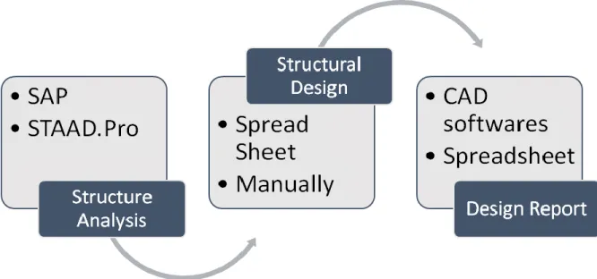
The designers in India use two step method to design a box culvert. First, they analyze the structure based on the size of the culvert and loads acting on it, to acquire the design moments using structural analysis applications like SAP or STAAD.Pro. Then based on these design moments, they design the structure as per the IS codes using an excel design sheet for box culverts. This excel design sheet will not automatically give the final design based on these moments, but needs some more input as it proceeds through design. The overall design process followed in India is represented in figure 1. This procedure followed
by engineers is time consuming as it involves manual input in design and is also prone to human errors.
Figure 1: Design Process Followed by Structural Engineers
Also, communication of design has always been a problem for construction industry. The design documents are communicated to the user via email or by hard paper copies. There is a potential of information getting lost over the period of time, as the hard copies (paper copies) can be lost or a soft copy (electronic copy) can get corrupted. Also, if a standalone computer based application is created for design automation, it has its own challenges. Thus if a web based application is generated, the information can be readily available every time, everywhere and has no threat of information getting lost. Being a web based application solves all the shortcomings of a standalone computer based application. This will not require any specific system or software required and will generate useful information in no time.
Aiming to overcome these hurdles or difficulties faced by the industry, this paper will discuss the process and method used to generate a web based application for designing of box culverts.
2. RESEARCH DESIGN
2.1 Research ObjectivesThe main objectives of this study are;
1) Developing a web based application for designing of box culverts using Indian standard codes.
2) To generate a design report for the box culvert using results from this application. 3) To verify the results generated from this application with design generated from
conventional method of designing. 2.2 Hypothesis
The web based application will be successful in designing the box culverts and will match the design generated by conventional method of designing this member.
2.3 Delimitation of the Study The delimitations of this study are
1) As this web application uses Indian standard codes for design of box culverts, it is only applicable to the Box culverts used in India.
2) The application developed in this study will concentrate only on single cell box culverts.
3) The design criteria used is based on normal concrete and uses normal weight of concrete to determine the self-load of the culvert. Thus, this can only be used where normal concrete is used for construction of box culverts.
2.4 Definitions
Design automation – It means generating design of a member directly by just inputting some basic information of the required member.
Culvert – A structure that allows flow of water through it which is usually used for a road or railroad construction is a culvert.
Stiffness Matrix – The matrix representing a set of linear equations that must be solved to obtain the solution of the differential equations of moments at each end of the box culvert is called stiffness matrix.
Normal concrete – Normal concrete is a concrete which contains basic ingredients of concrete i.e. aggregate, water, cement in normal common ratios.
Self-weight – The weight of the structure itself due to the concrete and reinforcement present in the structure.
3. LITERATURE REVIEW
Indian economy has grown substantially in last few years at about 8-10% every year. Central government and state government in India have launched several transportation infrastructure developments in last few years. Road sector expenditure which was budgeted to be 3% in the 9th five year plan in India, has increased to 12% by 2012 (World Bank, 2008).
3.1 Advantages of Box Culvert
Box culverts are most commonly used culverts in a road construction where water is passed across the road. Box culverts have many advantages in terms of both strength and economy. Box culverts are economical as its monolithic construction provides it rigidity and also as the bottom slab is laid directly on the soil it serves as raft foundation (Kattimani & Shreedhar, 2013).
The box culvert has advantage over others based not just on strength and economy, but also on ease of design, construction, and almost no maintenance. Also, it is easier to install box culverts next to existing box culverts in the event of road widening. It can be placed on soft soil which has low bearing capacity and can be placed at any elevation in the embankment. Single cell culverts are used where the flow of the water across the water is low (Sinha & Sharma, 2009).
3.2 Problems in Design
Based on the report published by World Bank (2008), 6% of the problems caused in the infrastructure development program are caused by inadequate design and drawings. The following constraints were identified in the report which were based on the interviews conducted of some contractors and consultants;
Cash flow
Delay in decision the employer Inadequate design and drawings Migration of experienced personnel Delay in payment
Procurement of critical materials and services Inadequacy of modern plant/Equipment.
A lot work has been done to improve the design of box culverts in India. Shreedhar and Shreedhar, (2013) worked on developing the design coefficients for single cell and two cell box culverts and found that using these design coefficients can reduce design time and effort. The study concluded that multi celled box culverts are economical for larger spans as compared to single box culverts. Also the study carried out by Kalyanshetti and Gosavi, (2014), found that using optimum thickness coefficient calculated based on this study instead of using conventional method of analysis which uses L/20 as the thickness of member can be successfully used to find the optimum thickness of member.
A study carried out to study the forces acting on the box culverts by Chen, Zheng, and Han, (2009), found that vertical pressure on the culverts depends on the height of the backfill, slope of trench and dimension of the culvert. A soil arch is formed as the backfill height increases which makes the vertical earth pressure acting on the culvert nonlinear with height of the backfill. But using this non linearity in the design makes it complex and cannot be handled by automated applications. Thus is not used in this study and a linear variation is considered.
3.3 Technology and Construction
In this world of globalization, the participants involved in construction are dispersed all across the world and this creates the problem of effective communication and information delivery. In modern world of construction where timely completion of project is highly important, the accuracy and timeliness communication of information is very important for success of a project (Shahid & Froese, 1998). Projects often experience extensive delays or rework due to information that is unavailable, inaccurate or outdated (Saidi, Haas, & Balli, 2002).
In last couple of decades, computer applications and computer aided design has brought a reformative revolution in construction industry. Many companies have developed computer applications to design simple but repetitive members, which will save a significant amount of time consumed in manual process (Kang, Lho, & Choi, 2004). They continue by stating advantages of web based application on standalone computers. Web based project management has been successful in database management for construction infrastructure (Kang et al., 2004).
Using computer applications for engineering designs have their own problems. Also the use of different computer software’s and platforms used within the industry makes this problem more severe (Anumba, Ugwu, Newnham, & Thorpe, 2002). The design problems which include multiple measures of performance can create compounding problems in using design applications (Simpson, Poplinski, Koch, & Allen, 2001). The problem in engineering design is that it uses many discrete variables and thus using computer based design optimization applications sometimes become difficult (Rajeev & Krishnamoorthy, 1992).
Thus the body of literature clearly demonstrates the growing popularity of box culvert in road construction and the development of web based applications for its design will help the construction industry in overcoming the problems faced in design process and communication.
4.
DESIGN PARAMETERS
Design Parameters on which the design of box culverts is based on is briefly described in this section.
4.1 Loading
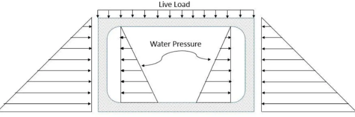
There are four types of load acting on the box culverts at any given time. Figure 2 shows all the considered forces acting on the box Culvert. These loads are;
Live load on the box due to the vehicular traffic on them, Dead load or self-weight of the box culvert itself,
Soil pressure acting on the side wall due to the earth fill on the sides of wall and Water pressure inside the culvert in case of water flowing through it.
Figure 2: Loading on Box Culvert
4.1.1 Live Load
There are different moving load combinations possible that are acting on the structure, but the most critical of 70R class loading which causes the maximum load to act on the box is considered in this study. The load intensity acting due to this case on the box is calculated for point load and then is applied on the box as uniformly distributed load. The
impact factor of 1.1 shall be applied to the live load which is commonly used for load calculations in most of the designs.
The effect of contact of wheel or track load in the direction of span length shall be taken as equal to the dimension of the tire contact area over the wearing surface of the slab in the direction of the span plus twice the overall depth of the slab inclusive of the thickness of the wearing surface (Indian Road Congress, 1998).
4.1.2 Soil Pressure
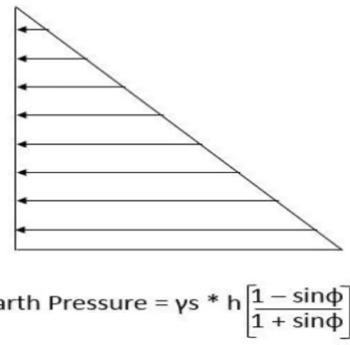
The pressure exerted by the earth fill on the retaining side of the box culvert is termed as soil pressure or active soil pressure. Soil pressure is assumed to act constantly at all the time on the walls and is represented as shown in figure 3. The degree of pressure exerted on the wall by the earth fill depends on two main parameters; coefficient of active earth pressure and Unit weight of soil. Coefficient of earth pressure is higher on the walls when the structure is backfilled after construction (Sinha and Sharma, 2009). The coefficient of earth pressure for normal soil is usually 0.33 but most of the designers use 0.5 unless and otherwise some typical conditions exist. In this study we use the coefficient of active earth pressure as 0.5. Unit weight of soil is different for different soils and cannot be predicted or assumed. Thus this is one of the design inputs for this study. The earth pressure on the walls of culverts is calculated as;
Figure 3: Earth Pressure on Walls
Here,
H - Height of the wall of the Box;
Sinф – Coefficient of active earth pressure; Γs – Unit weight of Soil.
4.1.3 Hydraulic Pressure
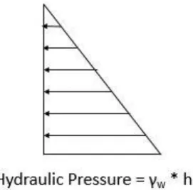
The water flowing through the box culvert will exert hydraulic pressure on the side walls. Hydraulic pressure depends on the height of the water level flowing through the culvert. The water may not always be flowing at its full depth through the culvert or may not be flowing at all. If the depth of water level flowing is less the hydraulic pressure exerted will be less. The hydraulic pressure acts similar to the earth pressure, but in opposite direction as shown in figure 4. It also depends on the unit weight of water which is constant i.e. 10 kN/m3.The hydraulic pressure acting on the member at any time is given as
Here,
γw - Unit weight of water,
h – Depth of water level inside the culvert. 4.2 Braking Force
Braking force acting on the box culvert with smaller cushion bed has higher effect on the structure instead of one with thick layer of cushion bed on it. This is because most of the force is absorbed by the cushion bed and very little reach to the structure below Also IRC: 6 -2000 clause mentions that there will be no effect to be considered on the box with cushion height greater than 3m (Indian Road Congressb, 2000).
The braking force produced by the vehicle on the roads or on the box culverts will cause the box to deform. In case of no cushion or small cushion bed, this effect is considerable. Most of the designers have difference in opinion about using braking force in design. But as it has impact on the box with no cushion bed or very small cushion bed, the impact due to the braking force is considered in this study. Now as the box culverts are
assumed to be monolithic and rigid framed, the braking force will be transferred to the end moments of the top slab, bottom slab and the walls. The effect of live load on the bottom slab is calculated based on clause 208, IRC: 6-2000. In this case, no reduction of load is considered and it is assumed that box culvert will be used on single lane road for maximum load (Indian Road Congressb, 2000).
4.3 Grade of Concrete
Grade of concrete is the actual compressive strength of concrete. Grade of concrete is a defining parameter for the thickness of members in design of box culverts. The higher the strength of concrete used, less is the thickness of members. As per IRC, minimum thickness of slab required is 200mm. This is based on the crack control criteria of concrete and is irrespective of the grade of concrete. Box culverts are constructed using various different grades of concrete which are usually 25MPa and 30MPa.
4.4 Grade of Steel
Steel grade is also a defining parameter in box culvert design. Amount of steel required depends on both grade of steel and concrete. Amount of steel required for each member is inversely proportional to grade of steel. Higher the grade of steel less is the amount of steel required. In Indian market steel with yield strength 250, 415 and 500 mPa are available and this study will be limited to use for only these type of steel.
4.5 Design Assumptions
The design of box culverts is based on some basic assumptions;
1) Single cell box culverts are assumed to be monolithically constructed, thus will be a rigid framed structure.
2) The live load due to the vehicular traffic applied on the structure will be through wheels will be considered as load structure.
3) IRC class AA tracked 70R loading case is used for design of box culvert in this study to take into account maximum live load acting on culvert at any time.
5.
RESEARCH METHODOLOGY
This research is designed to generate a web based application which will automatically generate the design for a single cell box culvert based on the input of basic requirement of design by the user. The IRC codes, IRC: 21-2000, IRC: 6-2000, IRC: 5-1998 and IRC: 78-2000 will be used to design the box culvert.
5.1 Design Process
The overall design of box culvert follows fixed steps as shown in figure 5. Normal weight concrete is only being consideration in this design, as this is what is usually used for culverts design. Seldom light weight concrete or pre-stressed concrete is used in box culverts. The unit weight of normal concrete is 24 KN/m3. The design process of box culverts follows a fixed step procedure.
Figure 5: Box Culvert Design Process
Designers follow the same design process for each design. First the parameters of the design as discussed in the previous chapter are defined. Based on these parameters, load acting on each member is determined followed by the moment calculations for each member.
All the load cases are treated separately to determine final design moments. Then using these design moments and IRC guidelines the final design of box is accomplished which includes the steel requirement and check of the performance of design for the shear forces acting on the box. Finally the design documents which include the detailed design are produced.
5.2 Load Calculations
Load on the bottom of the slab includes dead load of the walls, top slab and self-weight of the bottom slab itself. Live load is transferred to the bottom slab through the walls of box culvert and will be arranged on the bottom slab evenly as per clause 208 IRC: 6-2000. Thus the total load on the bottom slab id the sum of dead load and the live calculated. Surcharge of the soil on the back side of the culvert, water pressure and lateral load due to live load acting on the top slab, are all the possible loads acting on the side wall. Now, to calculate the maximum load acting on the side walls of the box culverts at any point, three load cases are considered.
5.2.1 Case 1
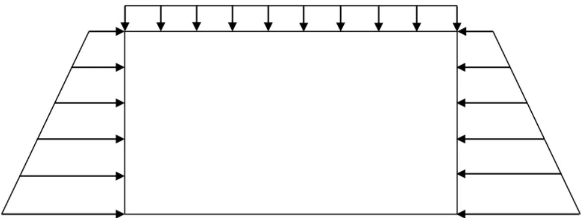
When no water is flowing through the box and live load is acting on the top of the culvert. In this case the maximum live load possible i.e. ‘AA’ class loading is considered which as per IRC and the lateral load acting on the side of the wall due to the earth pressure as shown in figure 6.
Figure 6: Wall Loading Case I
5.2.2 Case 2
When box is full of water and live load is acting on the top slab. In this case lateral pressure acting on the wall due the water flowing through the box culvert and the pressure acting due to the earth on the other side of the wall as shown in figure 7.
Figure 7: Wall Loading Case II
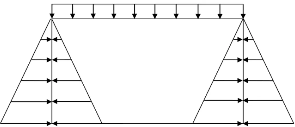
5.2.3 Case 3
When box is full of water but no live load is acting on the culvert. In this case only the surcharge load due to water and earth fill will be acting on the side wall as shown in figure 8.
Figure 8: Wall Loading Case III
5.3 Moment Calculations
End moments and mid span moments of each member is calculated based on the total load acting on them. For side walls, moments will be calculated separately based on the total load obtained from each case. Moments due to live load and dead load on the top and bottom slab is a uniformly distributed load, thus
End moment is calculated as W * l2 /12 and mid span moments as W * l2 /8.
For the side walls, live load will be uniformly distributed as surcharge load but earth pressure and live load will be a triangular load as shown above, thus
Top Moments: Due to Dead load = W*l2 /30;
Due to Live load = W * l2 /12
Bottom Moments: Due to Dead Load = W * l2 /20;
Due to Live load = W * l2 /12
Mid span Moments: Due to Dead load = W * l2 /16;
Here, W – Uniform load acting on the member; l – Length of the member.
Moments on the side wall will be calculated separately for all the three cases and is treated independently and has independent code behind line in C#. Figure 9 shows the code behind syntax for moment calculations using C#. For each case, moments acting on the top and the bottom slab will remain the same as shown above. The end moments acting as a combined effect of all the three members end moments separately, is calculated by using Moment distribution method.
Figure 9: Code Behind for Moment Calculations
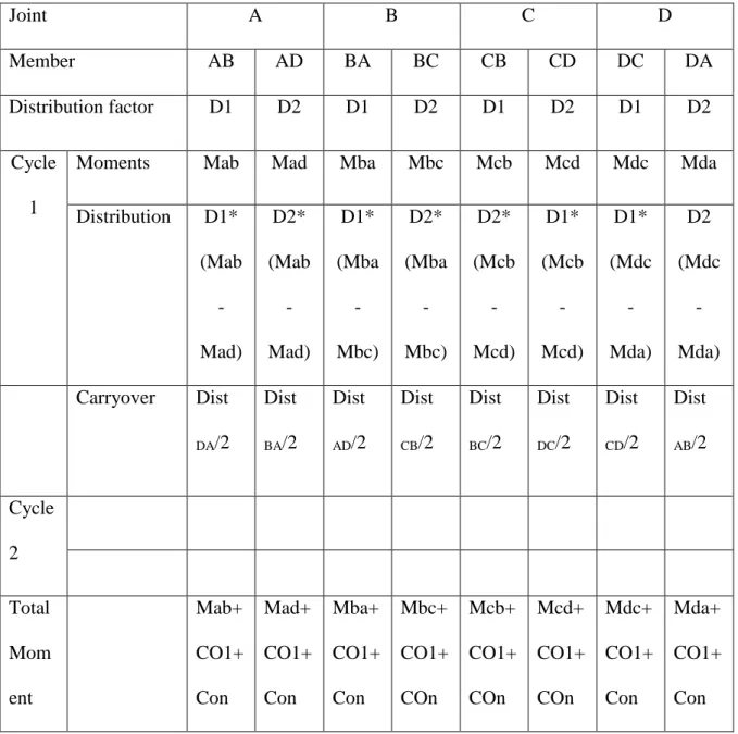
5.3.1 Moment Distribution Method
Moment distribution method is applied separately to each case to calculate the final end moments on the box culvert. Table 1 is used to compute the final end moment based on moment distribution method. The moment distribution is carried out to obtain the balanced moments at the supports. The distribution of the moments take place based on the distribution factor for each node, which is calculated based on the stiffness matrix produced for the box culvert.
Figure 10: Stiffness Matrix (Sinha & Sharma, 2009)
In the stiffness matrix shown in figure 10, we have assumed the thickness of the top slab, bottom slab and side walls to be the same. Thus, I1 = I2. Also as the box is constructed
monolithically, all the ends of the box culvert are fixed ends. After solving this stiffness matrix it is observed that,
Distribution factor for the node = (1/L1) / (1/L1 + 1/L2);
Table 1: Moment Distribution at Joints Joint A B C D Member AB AD BA BC CB CD DC DA Distribution factor D1 D2 D1 D2 D1 D2 D1 D2 Cycle 1
Moments Mab Mad Mba Mbc Mcb Mcd Mdc Mda
Distribution D1* (Mab - Mad) D2* (Mab - Mad) D1* (Mba - Mbc) D2* (Mba - Mbc) D2* (Mcb - Mcd) D1* (Mcb - Mcd) D1* (Mdc - Mda) D2 (Mdc - Mda) Carryover Dist DA/2 Dist BA/2 Dist AD/2 Dist CB/2 Dist BC/2 Dist DC/2 Dist CD/2 Dist AB/2 Cycle 2 Total Mom ent Mab+ CO1+ Con Mad+ CO1+ Con Mba+ CO1+ Con Mbc+ CO1+ COn Mcb+ CO1+ COn Mcd+ CO1+ COn Mdc+ CO1+ Con Mda+ CO1+ Con
A logic which will compute the total moments based on the moment distribution matrix is generated and integrated in this application. This module for Moment distribution matrix is used for all the three cases for moment calculation. These fixed end moments generated from these cases are compared, and the largest of the three values is used at each member independently. This means, that it will not matter if Member AB has the highest
bending moment from case 2 and member BC has the maximum moment generated from case 3, Member AB will have obtain the highest generated value generated of all the cases i.e. from case 2 and for member BC from case 3.
5.3.2 Braking Force Effect
Now, the effect of braking force as mentioned in design parameters chapter will be applied to these distributed moments. First the difference of moment at each node is distributed to the members associated with the node based on the distribution factor of each member. Then the distributed moment is carried over to the next end of the member. For example, carry over from member AB to member is carried over to BA and then the carry over moments at each end are again distributed and the cycle continuous, until the
distribution value becomes less than 0.1. The final fixed end moments are obtained by summation of fixed end moment and all the carry overs for that member.
Finally to get the design moments, the moments generated due to the braking force are applied to the distributed moments. As per IRC:6-2000 clause 214.7, the braking force acting on the top of the box culvert will generate moments at fixed ends of both walls and the top and bottom slabs having zero fixed end moments.
5.4 Reinforcement Requirements
Based on the design moments, the area of reinforcement required at each section is calculated. As mentioned in previous chapters the area of steel required depends upon the grade of steel and grade of concrete. Bureau of Indian Standards (1978), gives the percentage of steel required at each section. This percentage of steel required then finally gives the actual area of steel required at particular section.
Based on the area of steel required, the steel will be provided to each member of the box including the extra reinforcement (if any) to be provided at each ends to counter the extra end moments generated. The spacing of rebar is calculated based on the size of rebar. Centre to centre (C/C) spacing of rebar is calculated per meter length of member and is given as,
C/C spacing = 1000 * Ast(required) / Aφ
Ast(required) – Area of steel required;
Aφ – Cross sectional area of rebar used for each member.
Based on the area of steel required calculated for each section, the reinforcement schedule will be generated in the final output.
6.
DEVELOPING THE APPLICATION
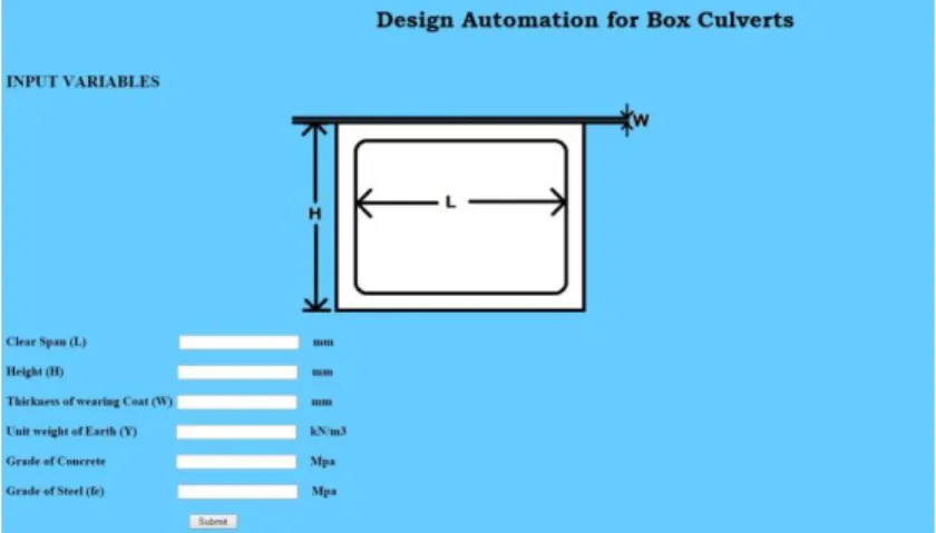
6.1 Using Visual Studio Express 2013Microsoft Visual studio express 2013 platform is used to generate this web application for Design Automation for Box culverts. The web form layout as shown in figure 9 is designed using html, which will accept input from the user. These input data will include height of the culvert required, span of the box, grade of steel, grade of concrete, unit weight of soil and thickness of wearing coat required. Unit weight of soil is required to understand the properties of land where these culverts will be placed and is used to determine the load on the walls of culvert. The design of culverts depends on the grade of steel and concrete to be used for this box. Then design criteria and design procedure as per IRC will be generated using C# code behind files.
Figure 11: Application Input Screen
6.2 Design Algorithm
The overall design of box follows a specific and standard design process. Figure 10 shows the flowchart used to generate the final design algorithm for this application. The
procedure. The code behind files for this application is generated using C# on visual studio platform. The code is generated based on generic algorithm followed by designers integrating analysis with design in one application.
Figure 12: Design Generation Flow Chart
6.3 Design Database
A database which includes tables for flexure of concrete structure based on SP 16: Design Aids for reinforced concrete to IS: 456-1978 is used. This database is created using Microsoft SQL server which is integrated with the application to generate the percentage of steel required for each member. The tables are generated only for M25 and M30 grade concrete for singly reinforced sections.
The program calculates Mu/bd2 based on the design moments obtained. The table is chosen from the database based on the grade of concrete used by the user. Then the ‘Reader’ function is applied to the selected table to search the calculated value of Mu/bd2 which reads the percentage of steel required depending upon the grade of steel used as defined by the user. This process is followed each top slab, bottom slab and side wall separately for end moments and mid-span moments each. Based on these percentages of steel values the area of steel to be provided at each section is calculated. These Design moments and area of steel required are brought to the output screen which includes the Design moments, Area of steel required and Area of steel provided.
6.4 Application Validation
To test if there is any time saving in using this application, the application is tested for the time required for the generation of design. The design time includes the input of variables in the application and processing time required for generation of results. Based on the time recorded for 25 different designs, the average time required by the application to generate the results is found to be 16 seconds.
The actual time required for traditional design process was collected based on responses from three structural engineers. Engineers were contacted over the phone and were asked for what is the actual time required for them to design one box culvert. Based on the responses from each of them, the average time required to complete one design is around 45-50 minutes. This time does not include the generation of final design drawing, it is just the time required for them to analyse the box and finally design the box. This can clearly be seen that the time required to generate the design using this application is almost negligible when compared to the actual time required by the designers.
The final design output generated from the application is tested with actual design of box culvert. This design was generated by the designer which includes using STAAD.Pro for analysis and then using the analysis results as design input in the Design excel sheet. Also the same box was manually calculated as per the IRC and IS standards and compared with the results obtained from the application.
Case I: A box culvert with length = 3m and height = 3840mm placed on the soil for a clear span of 8m with unit weight 18 kN/m3 is designed using M25 grade concrete and Fe 415 grade steel. The culvert is used for in an 8 lane divided carriage way which has wearing coat of 65mm on the top of the box. Table 2 shows the results obtained from the designed application for this case. Table 3 and table 4 shows the computed design moments obtained using manual design process and from using STAAD.Pro respectively. Figure 13 shows the moment comparison at each section of the box culvert using all three design process.
Table 2: Application Design Output – Case I
Member End Moments Midspan Moments
Mad Mba Mcb Mdc AB DC AD
Moments 113.01 113.01 64.23 64.23 111.31 56.65 -35.5 Steel Required 1176.9 1176.9 986.3 986.3 1120.6 793.8 567
Table 3: Manual Process Design Output – Case I
Member End Moments Midspan Moments
Mad Mba Mcb Mdc AB DC AD
Moments 120.79 120.79 79.02 79.02 95.09 51.18 31.57 Steel Required 1849.6 1849.6 1299.8 1299.8 1456 841.8 483.4
Table 4: STAAD.PRO Design Output - Case I
Member End Moments Midspan Moments
Mad Mba Mcb Mdc AB DC AD
Moments 116.45 116.45 74.23 74.23 103.29 64.23 29.63 Steel Required 1685.7 1685.7 1128.8 1128.8 1586 981.8 518.6
Figure 13: Moment Comparison with Each Design Methods for Case I
Case II: A box culvert with length = 4m and height = 3m with clear span = 6m placed on the soil with unit weight 22 kN/m3 is designed using M25 grade concrete and Fe 415 grade steel. The culvert is used for in a 2 lane divided carriage way which has wearing coat of 65mm on the top of the box. Table 5 shows the results obtained from the designed application for this case. Table 6 and table 7 shows the computed design moments obtained using manual design process and from using STAAD.Pro respectively.
Table 5: Application Design Output - Case II
Member End Moments Midspan Moments
Mad Mba Mcb Mdc AB DC AD
Moments 171.47 171.47 79.89 79.89 156.01 74.65 -77.15 Steel Required 2312.2 2312.2 1021.6 1021.6 2102.2 981.225 981.225
Table 6: Manual Process Design Output - Case II
Member End Moments Midspan Moments
Mad Mba Mcb Mdc AB DC AD
Moments 177.44 177.44 85.83 85.83 180.51 67.86 -70.2 Steel Required 2556.4 2556.4 1214.3 1214.3 2665.3 1056.6 1123.6
Table 7: STAAD.Pro Design Output
Member End Moments Midspan Moments
Mad Mba Mcb Mdc AB DC AD
Moments 183.35 183.35 83.4 83.4 172.64 69.56 -71.56 Steel Required 2244.6 2244.6 1228.7 1228.7 2654.6 1456.6 946.6
The average difference in the moments between the manual design process and the results obtained from the application based on both cases is shown in table 8 below. The table shows the percentage of difference obtained between both manual design process and developed application for each of case 1 and 2.
Table 8: Difference in Moment Comparison
Member End Moments Midspan Moments
Mad Mba Mcb Mdc AB DC AD % Difference in Moments (Case 1) 0.68 0.68 18.69 18.69 14.65 9.7 12.56 % Difference in Moments (Case 2) 3.48 3.48 7.44 7.44 15.7 8.47 9.01
Figure 14 shows the comparison of the moments obtained on the box culvert with each of the three design methods. Based on this the mean of percent difference is calculated by adding all the percentage difference for each member and then dividing it by the total number. The mean of difference in the moments based on the above table is found to be 9.33%. 0 20 40 60 80 100 120 140 160 180 200
Mad
Mba
Mc b
Mdc
MAB
MBC
MAD
CASE II
Application
Manual Process
Excel
6.5 Time Saving
The application was run for 30 times and the time required to obtain the final design report is recorded in figure 15 to get an average time required by the application to generate the final design report. The time in each case was recorded using an I-phone stopwatch. The average time recorded for these 30 cases is found to be 17 seconds. This time includes the time required to input the design parameter in the input screen and the time required for processing the report.
Figure 15: Design Time Recorded by Using the Application
The design calculations were performed manually for 10 cases and recorded in figure 16 following the procedure mentioned in above chapter. The time required for each design calculation done manually was recorded using the same procedure followed to record the time for the application. The average time for these 10 design cases calculated manually is found to be 53 minutes.
0 20 40 60 80 0 2 4 6 8 10 Tim e Re q u ir ed (Mi n ) Case
Manual Design Process
7. CONCLUSION AND SIGNIFICANCE
7.1 ConclusionThe results obtained from the application testing makes it very clear, that a considerable time of the designers can be saved in using this application. Being a web based application the problem of loss of information is eliminated. Also the communication of information between all the parties involved in construction of box culverts will become very easy.
Based on the results, it can be concluded that this application is reliable and can be successfully used in designing the box culverts of different sized with acceptable output. The design moments and steel required generated by this application are very close to the results obtained from manual design and can be successfully used in designing of box culverts used for road construction in India.
7.2 Significance
The study is a unique contribution in improving the construction design process. The study integrates the design codes and analysis of the structures in one package which results in substantial time saving. The application successfully generates a design report which reduces the manual process of generating the design report after the design process.
This study opens gates for further research in the field of Design automation. Application which deals with single cell box culvert, two cell box culvert and multi cell culverts can be developed which will intelligently choose the type of culvert based on the span of the culvert. Also, this application can be further developed to produce the final design documents.
REFERENCES
Anumba, C. J., Ugwu,O.O., Newnham,L., & Thorpe,A. (2002). Collaborative Design of Structures Using Intelligent Agents. Automation in Construction 11.1: 89-103.
Bureau of Indian Standards (1978). Design Aids for Reinforced Concrete to IS: 456-1978 (Report No. UDC 624.012.45.04 (026)). New Delhi: Bureau of Indian Standards. Retrieved from
http://archive.org/stream/gov.in.is.sp.16.1980/is.sp.16.1980#page/n7/mode/2up
Chen, B. G., Zheng, J. J., & Han, J. (2009). Experimental Study and Numerical Simulation on Concrete Box Culverts in Trenches. Journal of Performance of Constructed Facilities, 24(3), 223-234.
Indian Road Congress (1998). Standard Specifications and Code of Practice for Road Bridge, Section I (Report No. IRC: 5-1998). New Delhi: Indian Road Congress. Retrieved from https://law.resource.org/pub/in/bis/irc/irc.gov.in.005.1998.pdf
Indian Road Congressa (2000). Standard Specifications and Code of Practice for
Road Bridges Section: II Loads and Stresses (Report No. IRC: 6-2000). New Delhi: Indian Road Congress. Retrieved from
http://manuneethi.in/FILES/IRC%20CODES%20&%20MORTH%20SPECIFICATIONS/IR
C-6-%28Road%20bridges%20Std.%20specifin.%20and%20code%20of%20practice-sec-Indian Road Congressb (2000) Standard Specifications and Code of Practice for Road Bridges Section VII, Foundation and Substructure (Report No. IRC: 78-2000). New Delhi: Indian Road Congress. Retrieved from
https://law.resource.org/pub/in/bis/irc/irc.gov.in.078.2014.pdf
Kalyanshetti, M. G., & Gosavi, S. A. (2014). Analysis of Box Culvert-Cost
Optimization for Different Aspect Ratios of Cell. IJRET: International Journal of Research in Engineering and Technology, 3(4), 508-514.
Kang, J. H., Lho, B. C., & Choi, S. R. (2004). Parametric Web-CAD for Box Culvert Design. Computer-Aided Design and Applications, 1(1), 147-152.
Kattimani, K. S., & Shreedhar, R. (2013). Parametric Studies of Box Culverts.
International Journal of Research in Engineering and Science, 1(1), 58-65.
Rajeev, S., & Krishnamoorthy, C. S. (1992). Discrete Optimization of Structures Using Genetic Algorithms. Journal of Structural Engineering, 118(5), 1233-1250.
Saidi, K., Haas, C. T., Tucker, R.L., & Balli, N. A. (2002). The Value of Handheld Computers in Construction. Evaluation, 13, 29-32. Retrieved from
Shahid, S., & Froese, T. (1998), Project Management Information Control Systems.
Canadian Journal of Civil Engineering, 25 (4), 735-754
Shreedhar, S., & Shreedhar, R. (2013). Design Coefficients for Single and Two Cell Box Culvert. International Journal of Civil & Structural Engineering, 3(3), 475-494.
Simpson, T. W., Poplinski, J. D., Koch, P. N., & Allen, J. K. (2001). Metamodels for Computer-Based Engineering Design: Survey and Recommendations. Engineering with Computers, 17(2), 129-150.
Sinha, B. N., & Sharma, R. P. (2009, October). RCC Box Culvert-Methodology and Designs Including Computer Method. Journal of the Indian Roads Congress, 189-219. Retrieved from
http://www.irc.org.in/ENU/knowledge/archive/Technical%20Papers%20for%20Irc%20Journ
als/RCC%20Box%20Culvert%20-%20Methodology%20and%20Designs%20Including%20Computer%20Method.pdf
World Bank (2008). India - Indian Road Construction Industry: Capacity Issues, Constraints and Recommendations (Report No. 46326-IN). Washington, DC: World Bank. Retrieved from