Study of MHD Effects in the High-Enthalpy Shock Tunnel
Göttingen (HEG) using a 30T Pulsed Magnet System
J. Martinez Schramm and K. Hannemann
DLR, Institute for Aerodynamics and Flow Technology, Department Spacecraft Bunsenstraße 10, 37073 Göttingen, Germany
Jan Martinez Schramm: [email protected]
Abstract The interaction between high-enthalpy partially ionized gas flows and magnetic
fields, mostly called magneto hydrodynamics (MHD), is regarded as a potential way to manipulate flows. One example is the wall heat flux mitigation during spacecraft re-entry or entry into an atmosphere. However, the theoretical background and the practical application are still discussed controversially. One way to enhance the knowledge in this field is to utilize advanced computational fluid dynamics (CFD) tools in combination with experimental studies providing suitable validation data. The German Aerospace Center, DLR, has assembled an experiment for the High Enthalpy Shock Tunnel Göttingen, HEG, to provide data for verification and validation of numerical predictions. A 30 T pulsed magnet, driven by a 100 kJ capacitor bank, generates the required field. This paper outlines the experimental requirements to obtain magneto hydrodynamic effects in high-enthalpy partially ionized gas flows and the final realization of the experiment. Selected results of experiments using flow stagnation enthalpies of 22MJ/kg are presented.
1 Introduction
The interaction between electrically conducting flows and magnetic fields, commonly referred to as magneto hydrodynamics (MHD), is regarded as a unique way to exert directed volume forces on the fluid. The potential for flight control, heat flux reduction and in particular phenomena of fundamental interest for applications like shock less deceleration of super- and hypersonic flow have been reported [10]. For years experimental MHD investigations suffered from drawbacks in engineering: mass and volume of classical magnets and power supplies, and limited capabilities in measuring flow parameters. Recent developments in superconductors and semi-conductors and new materials helped to overcome many technical difficulties. Advanced numerical tools, capable of handling the coupled Navier Stokes/Maxwell equations, still lack experimental verification and validation. Ambitious proposals revived the general interest in MHD and call for the availability of reliable experimental reference data, focussing e.g. on manipulating the gas dynamic bow shocks of spacecraft for heat flux reduction [7]. In this paper we outline an experiment designed for the High Enthalpy Shock Tunnel Göttingen (HEG) of the German Aerospace Center (DLR). The experiment, which is suitable to investigate MHD-effects will provide experimental background for theoretical analysis and is designed to be a reference case for verification and validation purposes. The experiment consists of a liquid nitrogen cooled 30T pulsed magnet, which is driven by a 100kJ capacitor bank. The coil is installed in a spherical. Modifications of the bow shock distance and shape can indicate changes in flow conditions and are easily accessible by non-intrusive optical measurement methods. To characterize MHD-relevant flow conditions, the standard set of non-dimensional flow quantities, like Mach number, Reynolds number etc. has to be extended. The magnetic interaction parameter, or Stuart-Number , relates the force exerted on the conducting fluid by the coil field to the
inertia force of the flow and is calculated as =B2l/(ρu), denoting the electrical conductivity of the gas, B the magnetic flux density generated by the coil, l a characteristic length, ρ the flow density and u the flow speed. Empirically, ≥1 ensures detectable effects of the magnetic field on the flow. In our case, an increase of the shock distance with increasing B is expected. The magnetic Reynolds number Rem relates the magnetic field
generated by the moving charged flow to the coil field. The magnetic Reynolds number is defined as Rem=μ0ul, with μ0 as the vacuum permittivity. For Rem << 1 the coil field clearly
dominates the field generated by moving charges. In the case of Q≥1 and Rem << 1 both the theoretical treatment and the interpretation of experiments are simplified in various ways. But when viewed in more general terms, the roles of and Rem and the interaction mechanisms
between conducting flow and magnetic field via Lorentz forces and secondary electric and magnetic fields are complex and still not completely understood nor investigated [7].
2 The High Enthalpy Shock Tunnel Göttingen, HEG
The HEG is one of the major European hypersonic test facilities. This free piston driven shock tunnel (Stalker type [12]) was commissioned for use in 1991 and has been utilized extensively since then in a large number of national and international space and hypersonic flight projects. HEG was designed to study the influence of high temperature effects such as chemical and thermal relaxation on the aerothermodynamics of entry or re-entry space vehicles [3][4][5][6] The HEG condition used for the experiments described in this paper is the condition I with a stagnation flow enthalpy of 22MJ/kg.
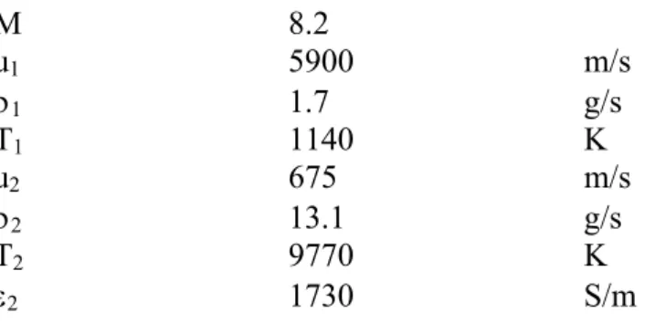
Table 1 Pre- and post-shock flow conditions for HEG condition I.
M 8.2 u1 5900 m/s 1 1.7 g/s T1 1140 K u2 675 m/s 2 13.1 g/s T2 9770 K 2 1730 S/m
The ionization induced in the shock layer of a blunt body in HEG at this flow condition produces a significant gas conductivity, which is an advantage for MHD experiments over alternatives like seeding the flow with alkali metals, electron-beam ionization or arcjet heating; these produce contamination or less well-defined free stream conditions. The pre- and post-shock flow conditions are given in Table 1.
3 Experimental Setup
To tailor the experiment to a systematic investigation of MHD phenomena, the following requirements were specified: The wind tunnel model is a hemisphere-cylinder with its axis aligned to the flow, having a diameter of D = 160 mm. This configuration has been tested to quit some extent in HEG and experimental as well as numerical reference data are available. The shock standoff distance ∆ is used as a reference length to evaluate the relevant Stuart Number .
Fig. 1 Schematic of the wind tunnel model in HEG on the left side and a photograph of the
model installed in the HEG test section on the right side
To achieve a Steward number ≥ 1 with the post-shock conditions in Table 1 and a shock
standoff distance of ∆ = 9 mm (sphere with D = 160 mm) a magnetic field of B≥1T is necessary at the shock location. A higher magnetic field is desirable, which helps to overcome the general uncertainties, the inhomogeneous flow field and the fact that decreases rapidly with distance from the ideal interaction point. The corresponding magnetic Reynolds number amounts to Rem = 0.014, which is a tolerable result. The coil is installed within the model in
order to minimize the distance to the interaction region ahead of the hemisphere. The model diameter is sufficiently small to prevent tunnel flow blockage; at the same time the optical path length through the shock layer for advanced non-intrusive laser methods is found to be acceptable. The rise time of the magnetic field must not exceed t ≈ 3 ms with good reproducibility (low jitter) to suit trigger constraints during the tunnel operation. The coil power supply must be mobile; coil, model, cabling and cooling must be demountable and sufficiently robust to withstand several experiment campaigns. Further details on the power supply have to remain for future publications. The effective measurement time using HEG operating condition I is in the order of t ≈ 1ms, therefore the coil operation follows a corresponding time scale and has to produce the maximum field only for a similar short interval.
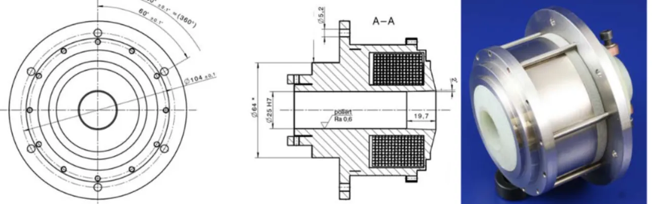
Fig. 2 Technical drawing of the coil used in the wind tunnel model and photograph.
In principle it is possible to generate a field of one Tesla fairly easily using permanent magnets; however, preliminary studies showed that the magnetic field of permanent magnets falls off very quickly with distance. Also, it is desirable to generate a higher magnetic field as the effects should scale with the Stuart Number which is proportional to B2. In general, fields
higher than a few Tesla are generated using electromagnets. The most economical way of generating high magnetic fields is doing this pulsed, which lends itself for this experiment as the field is only required for about a millisecond. Pulsed magnets are usually driven by a
capacitor bank, which leads to a half-sinusoidal pulse. This is common practice for condensed matter physics research; a number of facilities worldwide offer fields in excess of 60T routinely [7][8]. The performance of a pulsed magnet is usually determined by two factors: the first is the mechanical strength of the employed materials, which limits the peak magnetic field which can be achieved. High strength materials are required due to the Lorentz force, which gives rise to a large magnetic pressure. The second important parameter is the electrical conductivity of the conductor material, which limits the pulse length. The better the electrical conductivity, the longer the pulse can be. Given that the material is crucial for a pulsed magnet, the material chosen for the present coil is Cu-Ag7-Zr0.05. Among the Cu-based conductor materials, the family of Cu-Ag alloys shows the highest conductivity at a given strength (or vice versa) at room temperature [1]. The performance is better at low temperatures; this is why the wind tunnel model was designed to include a liquid nitrogen cooling system for the coil. An unusual challenge for the magnet design lies in the fact that the field is not required at the centre of the magnet, but rather far away from it in the fringe field region. Therefore, a monolithic coil geometry with an inner diameter of 40 mm, an outer diameter of 80 mm and a length of 30 mm was chosen. The coil was designed in cooperation with the high magnetic field lab in Oxford, UK and manufactured there. A technical drawing and a photograph of the coil is given in Fig. 2. Of importance is the exact knowledge of the
magnetic field distribution that the magnetic coil will generate when it is energized. A lot of effort was put into the exact measurement of the distribution of the magnetic field around the wind tunnel model, as it is of importance to the exact modelling of the interaction with CFD.
Fig. 3 shows a result of these measurements. Even tough lot of metal pieces belonging to the
model and liquid nitrogen tubing system are necessarily disturbing the magnetic field, it is quite homogenous and axisymmetric.
Fig. 3 Measurements of the magnetic flux density field around the coil using a low energy
measurement technique. The origin of the z-coordinate is at the maximal magnetic flux density on the axis of the coil.
4 Experiment and Results
The experiments in HEG where performed with varying magnetic flux density of the magnetic field around the hemisphere-cylindrical model. The varying magnetic flux density was changed by charging the capacitor bank that drives the coil with different energy levels.
Prior to the run, the magnetic coil installed in the wind tunnel model was cooled by pumping liquid nitrogen through its core. The inner resistance of the coil dropped typically from 130 m down to 60 m. Once the resistance measurements equilibrated, the coil was regarded to be cooled down homogenously. This process, performed under the tunnel vacuum usually took about 2 hours. The coil was then energized by discharging the capacitor bank into the coil. The maximum voltage of the half-sinusoidal pulse was at 3.5kV having a current of 13 kA. The charging process of the capacitor bank had to be finalized a few seconds before the run. The discharged of the capacitor bank into the coil was synchronised to the run to obtain a steady magnetic field during the test time. Fig. 4 shows the results obtained. A
numerical modelling result of the flow around the spherical part of the model for no magnetic field is shown on the top of each image. The density distribution of the CFD data is shown in false colours. On the bottom side, the Schlieren images obtained from the experiments are given. The experimental results are given for the case of no magnetic field, the case with B = 1 T magnetic flux density in the middle and B = 4.5 T on the right. The magnetic flux density is given at the axial position, where the shock wave stands for the measurement without any magnetic interaction. The change in shock stand-off distance is clearly visible. In the case of the strongest magnetic field the shock standoff-distance is increased by a value of 4.6. Not only is the shock stand-off distance influenced, but the complete flow field. The shock shape changes drastically on the changes are observable through the complete flow field. The exact description of the changes will be given in future publications.
Fig. 4 Comparison of numerical modelling of the flow around the sphere for HEG condition I
always on top (density) to the experimental data obtained with Schlieren visualization for the cases of (B = 0 T, B = 1 T and B = 4.5 T) from left to right.
5 Conclusions
Experiments demonstrating the interaction with high-enthalpy partially ionized gas flow and magnetic fields of varying magnetic field flux have been presented. The interaction has been shown by presenting measurements of density gradients with Schlieren visualisations. The change in shock shape and shock stand-off distance with acting magnetic field is clearly visible. The design and layout of the wind tunnel model holding the liquid nitrogen cooled magnetic field coil has been discussed. The basic ideas to design the experiment as a validation and verification test case have been sketched. The next steps in the process of the
establishment of a real test case will be to perform additional experiments and compare these to numerical modelling results with coupled Navier Stokes/Maxwell equations.
References
[1]Freudenberger, J., Kozlova, N., Gaganov, A., Schultz, L., Witte, H., Jones, H.:
Magnetoresistance up to 50 T of highly strengthened CuAg conductors for pulsed high field magnets. Cryogenics 46, 724-729, 2006
[2]Gülhan, A., Esser, B., Koch, U., Siebe, F., Riehmer, J., Giordano, D., Konigorski, D.: Experimental Verification of Heat-Flux Mitigation by Electromagnetic Fields in
Partially-Ionized-Argon Flows. Journal of Spacecraft and Rockets 46(2), 274-283,2009 [3]Hannemann, K., Martinez Schramm, J., Karl, S., Recent extensions to the High Enthalpy
Shock Tunnel Göttingen (HEG), Proceedings of the 2nd International ARA Days "Ten Years after ARD", Arcachon, France, 21-23 October, 2008
[4]Hannemann, K., Krek, R., Eitelberg, G., Latest Calibration Results of the HEG Contoured Nozzle, In: Sturtevant, B., Sheperd, J.E., Hornung, H.G. (Eds.), Proceedings of the 20th International Symposium on Shock Waves, Pasadena, CA, USA, July 1995, pp. 1575-1580, World Scientific, 1996
[5]Hannemann, K., Martinez Schramm, J., High Enthalpy, High Pressure Short Duration Testing of Hypersonic Flows, In: Springer Handbook of Experimental Fluid Mechanics, pp. 1081 – 1125, Springer Berlin Heidelberg, Eds.: Tropea, C., Foss, J., Yarin, A., 2007 [6]Hannemann, K., High Enthalpy Flows in the HEG Shock Tunnel: Experiment and
Numerical Rebuilding, 41st AIAA Aerospace Sciences Meeting and Exhibit, 6-9 Jan, Reno, Nevada, 2003
[7]Herlach, F., Pulsed Magnets for Strong and Ultrastrong Fields. IEEE Transactions on Magnetics 4(32), 2438-2443, 1996
[8]Miura, N., Herlach, F.: Pulsed Strong and Ultra-Strong Magnetic Fields. Technical Report of ISSP Ser. A, No. 1471, The Institute for Solid State Physics, University of Tokio, Roppongi, Minkato-Ku, Tokyo 106, Japan, 1984
[9]Poggie, J.: Numerical modeling of electro-magnetic control techniques for high-speed flows. In: O.Chazot, M.Huber (eds.) Introduction to Magneto-Fluid-Dynamics for Aerospace Applications, VKI Lecture Series 2004-01, pp. 1--21. von Karman Institute, Rhode Saint Genese/Belgium (2004)
[10]Resler, E., Sears, W.: The prospects for magneto aerodynamics. Journal of the Aeronautical Sciences (No. 4), 235-245, 1958
[11]Shang, J.S.: Shared knowledge in computational fluid dynamics, electromagnetics, and magneto-aerodynamics. Progress in Aerospace Sciences 38(6-7), 449-467, 2002 [12]Stalker, R.J., A Study of the Free-Piston Shock Tunnel, AIAA Journal, Vol. 5, No. 12,