California Polytechnic State University, San Luis Obispo
Additive Manufacturing for Post-Processing
AMPP
Final Design Report
Sponsor:
AMPP Team:
Andrew Furmidge Nathan GoodwinAdvisor:
Peter SchusterTable of Contents
Table of Contents ... i
List of Figures ... iii
List of Tables ... v
Introduction ... 1
Background ... 1
What is Additive Manufacturing? ... 1
Selective Laser Melting ... 2
Joining Methods ... 4 Manufacturing Considerations ... 10 Relevant Patents ... 11 Interviews ... 11 Objectives ... 12 Problem Statement ... 12 Customer Requirements ... 12 QFD... 13 Engineering Specifications ... 13 Design Development ... 14 Ideation ... 14
Description and sketches... 16
Selection Process ... 24
Description of Top Three Methods ... 25
Justification of Top Three Methods ... 28
Preliminary Plans for Construction and Testing ... 29
Safety Hazard Identification ... 32
Final Design Details – CDR ... 34
Design Description... 34
Justification ... 37
Manufacturing Plan ... 45
Design Verification Plans ... 54
Bill of Materials and Cost Analysis ... 54
Manufacturing ... 54
Final Design Changes ... 55
Testing Fixture ... 57
Updated Flowchart ... 58
Notes Taken on Manufacturing ... 64
Testing... 69
Notes Taken on Testing ... 69
Future Works ... 72
Printed Part Geometry... 72
Soft Jaw Geometry ... 73
Heating Considerations ... 73
Final Part Strength Analysis ... 74
Management Plan... 74 Gantt Chart ... 75 References ... 75 Appendices ... 1 Appendix 1: Patents ... 2 Patent 2 ... 5 Appendix 2: QFD ... 9
Appendix 3: Part with GD&T ... 10
Appendix 4: Pugh Matrix... 11
Appendix 5: Weighted Decision Matrix ... 12
Appendix 6: Hand Calculations ... 13
Appendix 7: Gantt Chart ... 18
Appendix 8: Drawing List and Part Drawings ... 26
Appendix 9: BOM... 55
Appendix 10: DVP ... 56
-List of Figures
Figure 1. LLNL powder level simulation of selective laser melting (1) ... 2
Figure 2. SLM 125HL (left) and SLM 280HL (right) (2) ... 2
Figure 3. Selective laser melting machine components (4) ... 3
Figure 4. Mortise-and-Tenon Joint developed in medieval times (5) ... 5
Figure 5. 3D CAD part split into pieces using computer program (6) ... 5
Figure 6. Cross section of a zipper joint (8)... 6
Figure 7. Loctite Epoxy Weld Bonding Compound (10) ... 7
Figure 8. Indium and Gallium coated rods from separation to connection and solidification (11) 8 Figure 9. Diagrammatic example of TIG welding (12) ... 9
Figure 10. Heating of casing for shrink fit (14) ... 10
Figure 11. Inserting carbide into heated casing (14) ... 10
Figure 12. Drawn over mandrel process of creating tubing (16) ... 11
Figure 13. All ideas generated during the brainstorming process, some containing sketches to explain general concept, most left ambiguous on purpose ... 15
Figure 14. Straight joint weld (1a) and straight joint adhesive (1b) ... 17
Figure 15. Puzzle piece weld (2a) and puzzle piece adhesive (2b) ... 17
Figure 16. Full thickness outer shell - heat shrink (3a, left) and partial thickness outer shell – heat shrink (3b, right) ... 18
Figure 17. Full thickness outer band (4a) and partial thickness outer band on both ends (4b) .... 19
Figure 18. Hook joint weld (5a) and hook joint adhesive (5b) ... 20
Figure 19. Button joint weld (6a) and button joint adhesive (6b) ... 21
Figure 20. Threaded cap band inside and outside with weld (7a) and threaded cap band inside and outside with adhesive (7b) ... 22
Figure 21. Internal band weld (8a) and internal band adhesive (8b) ... 23
Figure 22. Dowel pin weld (9a) and dowel pin adhesive (9b) ... 23
Figure 23. Drawn over mandrel (DOM) method (16) ... 25
Figure 24. Layout drawing of the heat shrink outer shell joining method. This drawing is based on a full thickness band... 26
Figure 25. Buckle clips found on backpacks, fanny packs, and various other gear (20) ... 27
Figure 26. Layout drawing of the button method to show assembly orientation ... 27
Figure 27. Layout drawing of puzzle piece joining method ... 28
Figure 28. LulzBot TAZ 6 (23)... 30
Figure 29. Tensile testing Instron in Cal Poly’s Composites Lab ... 31
Figure 30. View of the three male teeth and two female teeth at the end of each printed part .... 35
Figure 32. Cross section of one side of the test piece assembly. ... 37
Figure 33. End of a printed segment. The arrow indicates the corner that forms between the three planar surfaces. Note that this idea has been rejected because of the corner’s difficult accessibility to clean ... 39
Figure 34. Sketches of lathe fixture ideas ... 40
Figure 35. Inner and outer diameter of the outer band compared to standard pipe size 6 schedule 40s. The distance between the max heights of each bar (OD and ID respectively) represents the amount of material that will need to be removed from that side. ... 41
Figure 36. Inner and outer diameter of the inner band compared to standard pipe size 5 schedule 40s. The distance between the max heights of each bar (OD and ID respectively) represents the amount of material that will need to be removed from that side. ... 42
Figure 37. Compressive stress versus strain of lattice ... 43
Figure 38. Thermal expansion trend of the outer band ... 44
Figure 39. Thermal expansion trend of the inner band ... 45
Figure 40. Joining process flowchart ... 47
Figure 41. Printed part with pilot holes ... 48
Figure 42. Alignment plate being fixed to the printed part... 49
Figure 43. Printed part, alignment plate, and 1-2-3 block in a vise ... 50
Figure 44. Assembly pattern of printed parts... 50
Figure 45. Final part segment with a flat mating surface ... 55
Figure 46. Soft jaw assembly ... 56
Figure 47. Testing fixture fully assembled with directional arrows to show how the Instron will pull the test parts apart ... 57
Figure 48. Testing fixture disassembled ... 58
Figure 49. Final flowchart of joining process ... 59
Figure 50. Soft jaw holding segment to mill face ... 60
Figure 51. Same set-up used to drill holes ... 60
Figure 52. Soft jaw set up to mill and drill holes of opposite face ... 61
Figure 53. Set-up of part for drilling counter-bores ... 62
Figure 54. Milling counter-bore, second attempt ... 63
Figure 55. Final results from counter-boring using second method ... 63
Figure 56. Drilling thru-holes into soft jaws ... 64
Figure 57. Drilling counter-bores into soft jaws ... 64
Figure 58. Milling arc into soft jaws ... 65
Figure 59. Turning OD of both hemi-cylinders to 5.318". ... 65
Figure 60. Attempt at parting off first hemi-cylinder but breaking the parting tool ... 66
Figure 61. Hemi-cylinders cut to axial height but still in need of cutting into hemi-circles ... 66
Figure 62. Facing text fixture side arms ... 67
Figure 63. Drilling thru-holes into hemi-cylinders ... 67
Figure 65. Cutting outer band with horizontal band saw ... 68
Figure 66. Distribution of printed part inner and outer diameters ... 70
Figure 67. Drilling of through holes on the segment’s mating surface ... 71
Figure 68. The circled area is where the drill bit began cutting into the soft jaw. This groove depth should be deeper, meaning that the drill bit was deflecting away from the face of the soft jaw, causing extra wear ... 72
List of Tables
Table 1. Engineering specifications derived from customer requirements... 13Table 2. Yield and ultimate tensile strength properties of stainless steel 316L from two different sources... 29
Table 3. Dimensions for all pieces in the test piece assembly ... 52
Table 4. Breakdown of costs for each assembly (tax not-included) ... 54
Introduction
Additive Manufacturing for Post Processing (AMPP) is a team comprised of two Cal Poly Mechanical Engineering students: Nathan Goodwin and Andrew Furmidge. The project is focused in the area of metal additive manufacturing (AM) machines, which are still a developing technology. Improvements have been made to the quality of the machines in the past years, but many limitations still exist. One of these is the inability to print parts that are larger than the build volume. In an effort to solve this problem, whole parts are divided into pieces that are printed individually. This team’s senior project is to create a joining method for Lawrence Livermore National Laboratory’s (LLNL) AM department. An employee at LLNL, Stephen Knaus, is providing the requirements of the joining method, and Professor Peter Schuster is advising the team through the design process.
Background
What is Additive Manufacturing?
Additive manufacturing (AM) is a process that can quickly create a final part or prototype. This process assists designers and administrators when making decisions on the development of a part by allowing them to hold and visualize a model. AM encompasses a variety of methods that create a part layer by layer from a specific computer aided drawing (CAD) file. Generally, the CAD file is made by a designer or engineer who uses a program to create a solid model based off a concept that the designer envisioned. CAD files can also be created through a scanning process of an existing part. The solid model is converted into a STereoLithography (STL) file, a file format recognized by most solid modelling programs. The STL file is imported into an editing program that generates the necessary code for the machine to print the part in layers. The editing program has the ability to create a lattice structure within the model. A lattice is a repeated framework of patterned elements that occupies the space within a model. It reduces the mass of a printed part, which results in a shorter print time and a strong, lightweight model. The general types of AM processes for adding layers of material are liquid polymer, discrete particle, and molten material. This project utilizes selective laser melting which is a discrete particle method.
Lawrence Livermore National Laboratory is a lab funded by the government that is investigating AM through experiments and simulations (1). They have developed models that analyze the process at the part level and the powder level as seen in Figure 1.
Figure 1. LLNL powder level simulation of selective laser melting (1)
Ideally, the results from these models are compared to the measured material properties of the final part along with data from sensors during the print. The purpose of these simulations and experiments is to find the correct parameters that the machines should be operated at to yield a high success rate of prints and to predict the properties of the part before the part is made. One of the AM processes that LLNL uses is selective laser melting (SLM). A distinction should be made between the process called SLM and the company called SLM. The company named SLM manufactures machines such as the SLM 125HL, SLM 280HL, and SLM 500HL in Figure 2 below, which create AM parts through the process of SLM. The post processing of these parts is essential to the final form of the part.
Figure 2. SLM 125HL (left) and SLM 280HL (right) (2)
Selective Laser Melting
SLM is a discrete particle powder bed fusion process that uses a laser to melt layers of metal powder (3). Since SLM is a welding process, it can only produce parts that are made from a weldable material. As with other welding processes, the liquid metal must be contained within an inert environment, usually consisting of Argon (4). Certain metal powders such as aluminum and titanium are composed of individual particles 5-50µm in diameter. The small size of these particles can cause them to react with the oxygen in the air and cause safety hazards, which is the reason why they will not be used in this project. Only stainless steel 316L will be used to create parts because it is not combustible in powder form. When creating a part, the powder is swiped across the top of the build plate in layers as the build plate lowers. In the simplified model of an SLM
machine in Figure 3, the powder layer that the laser is melting stays at a constant height relative to the laser to keep the beam focused.
Figure 3. Selective laser melting machine components (4)
The difference between the model in Figure 3 and the SLM printer is that the SLM printer has a gravity-fed powder stock that drops powder in front of the powder roller for application of a new layer to the powder bed. The area of the powder bed, or build platform, limits the extents of the build volume. A larger build volume is often times desired, but increasing the size of the powder bed requires changes to the components of the machine such as the laser, mirror, and the actuator under the build platform. To compensate for having a smaller build volume, larger parts can be scaled down to fit within the build volume, although this may be insufficient for some prototypes. Some prototypes require dimensions that cause the part to be larger than the build volume; therefore, one of the limitations of the SLM process is the build volume. Additionally, the size of the printed part is proportional to the build time, so there is a tradeoff between the size of the part and the printing time.
In the case of this project, the desired part is slightly bigger than the build volume of the SLM 125HL model. The SLM 280HL model would be required; however, a bigger model printer is more expensive. This drives the need for joining method to be developed that will be applicable to axisymmetric parts of any scale. This method will allow axisymmetric AM parts to be made that are larger than the build volume of the largest AM machine. The joining method will require the part to be printed in sections and joined.
Joining Methods
For centuries, artists and designers have encountered the problem of not being able to build their masterpiece in one single part. One of the oldest examples dates back to the Egyptians and their pyramids. This issue still plagues the endeavors of today's designers and engineers as they strive to create things that were once thought to not be possible. Since then, there have been several methods tried and revised to connect pieces together. Some of these discoveries are more recent as technology has advanced, allowing designers to use a larger breadth of materials. This project will not utilize hardware fasteners, as required by the customer, narrowing down the number of potential joining methods. The first type of joining methods that will be discussed are mechanical fastening methods that use locking geometries, such as puzzle pieces and zippers. The next type of joining methods discussed will be adhesive joining methods that create a bond between two surfaces using a liquid bonding agent. Adhesives contrast with the next joining method of welding because welding melts the two surfaces together rather than adhesives use a different material for bonding. Lastly, shrink fits will also be investigated because this method is similar to welding since it does not require additional materials for joining.
Puzzle Pieces
One of the oldest joining methods is the use of physical connections or interlocking pieces to lock two pieces together. A puzzle piece is a prime example of how this method works. It involves one end of a part to be cut into a specific geometry such that there is a protrusion from the surface known as the male connector. The other part requires a similar cut on the necessary end, but instead, an inward cut that reflects the outline of the protrusion from the male end. This part is called the female connector and when the two parts are designed correctly, they can lock into place simply by sliding the male (key) side into the female (lock) side. The benefits are profound since a designer can design a fully completed part then choose the sections to split the part into by drawing simple or complex geometries to lock them together. The woodworking industry generated one of the first examples of this methodology in medieval times, using what is known as a mortise-and-tenon joint seen below in Figure 4.
Figure 4. Mortise-and-Tenon Joint developed in medieval times (5)
Since the Mortise-and-Tenon Joint, hundreds of more joints were created and utilized in different mediums from wood to stone to metal. More recently, the plastic 3D printing industry has created a process of turning any CAD model into multiple puzzle pieces that fit together. The program can create interlocking pieces in such a way that they become fixed in all three directions. Figure 5 below shows how this computer program can take a CAD model and split it into multiple pieces.
Figure 5. 3D CAD part split into pieces using computer program (6)
Potential disadvantages to the puzzle piece method lies in the strength of the projected ends, the tightness of the fits, and the effects of the direction of the applied force. If the puzzle piece end of
a part is poorly designed, it may create areas of high stress concentration and may cause those areas may fail before the rest of the part. Cutting creates tolerances in parts and if not calculated properly can lead to the puzzle pieces having either too much clearance or interference. In addition, if the puzzle piece experiences a force in the direction that it was slid together, there is a chance that the connection may undo itself, rendering the joint useless.
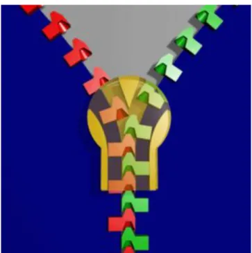
Zippers
A zipper is a joining device that integrates the basic hook and hollow geometries. The teeth of a zipper interlock to join the surfaces of two materials that are generally flexible. Shown in Figure 6, the slider of the zipper consists of a wedge and each tooth has a hook and hollow. Each opposing tooth is offset from one another so that their hooks and hollows can latch together in sequence (7). The track of the zipper is the pattern of dozens to hundreds of teeth. Generally, the wedge shaped slider forces the teeth of each track together at an angle. Parts made through AM are generally not flexible enough to deform to the angle required to allow the teeth to lock together, however, the idea of interlocking hook and hollow geometries may be useful to lock pieces together.
Figure 6. Cross section of a zipper joint (8)
Gluing
Another form of joining that has existed for quite some time is gluing. The specific substrate for gluing varies depending on the application, but all substrates function to adhere two pieces together. Glue usage ranges from mortar (used to hold concrete and brick) to epoxy (used to bond metal, Figure 7) and almost everything in-between. Glue is a widely used joining method because it can be quick and completed without much dexterity. The substance is applied to the end of one
part and is pressed tightly against the end of another part. Once again, the type of glue will determine how long it takes for the glue to cure (harden and complete the joint). The strength of the glue is dependent on how well the substance can adhere to the part, how strong the substance is when it has finished hardening, and how tight the fit is between the mating parts. The company Henkel/Loctite claims that out of the entire surface area of the desired joint, only about 15% of the joint’s surface area is actually forming metal to metal contact (9). Glue or retaining compound should be added to the joint to fill the gaps and increase the area of contact. Despite the advantages of glue, there are restrictions on the applications glue can be used for. Possible drawbacks occur when there is poor adhesion between the glue and part, when the operating temperature exceeds the limit of the glue, or when the glue reacts with other liquids such as water. Glue can be combined with geometric joining features, such as a puzzle piece, to increase the strength of the joint by improving load transmission.
Figure 7. Loctite Epoxy Weld Bonding Compound (10)
Chemical Bonding
Chemical bonding is another unique process which requires little effort from the user to obtain a strong connection. This process is similar to gluing since the bonding strength is dependent on the joining material used, but it utilizes the interactions between elements to ignite chemical reactions. One use of chemical bonding involves the elements Indium and Gallium. The bonding surfaces are initially coated with a layer of angled rods. One side has rods coated in Indium and Gallium coats the other side shown in Figure 8.
Figure 8. Indium and Gallium coated rods from separation to connection and solidification (11) When the two sides are slid into one another, similar to a zipper, the elements come into contact and form a liquid due to their elemental properties. This liquid reacts chemically and begins to solidify until it hardens completely. The chemical reaction between Indium and Gallium occurs at room temperate and requires no pressure while it is curing, which makes it similar to gluing, but it solidifies as a full metallic piece. The drawbacks are in the amount of time it would require to coat each side with the elements and the precision of the rods’ incidence angle.
Welding
The most common form of modern welding was first discovered in the early 1800s when an arc was created to melt metal in order to fuse parts together. Since its conception, the process has been iterated to account for different metals and applications. There are multiple benefits of welding compared to the previous two joining methods. Welders can choose what type of metal will be used to melt the two parts together based on the need of the designer. Once the weld solidifies. The weld bead typically surpasses the strength of the base material, however the heat affected zone besides the weld bead experiences a decrease in strength. There are other limitations to welding such as creating large amounts of heat. Too much heat could burn a hole through the metal, but not enough heat could cause the metals to fuse incompletely. An improper weld could contain porosity or other impurities that can decrease the strength of a weld. Another problem with welding is the amount of skill required to perform an acceptable weld. Below in Figure 9 is an example of the Tungsten Inert Gas (TIG) welding technique that utilizes a tungsten electrode to create the arc that melts filler rod, which must be applied by hand.
Figure 9. Diagrammatic example of TIG welding (12)
Shrink Fitting
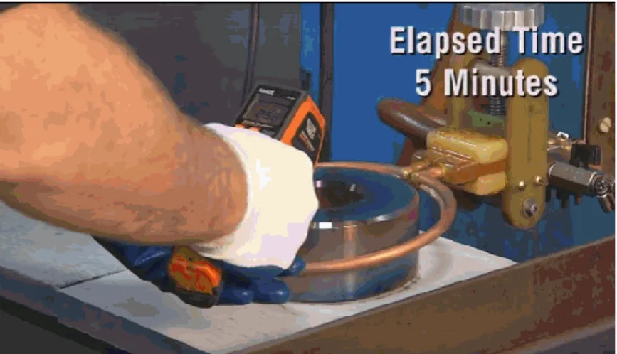
When extra material is not desired due to the nature of the application, heat shrinking can be used to join objects together. One use of heat shrinking is in underground piping. These pipes are buried under the surface, leaving them prone to wear and deterioration from moisture and other environmental factors. To combat this, wraps made from a flexible material are wrapped over or slid around the tube and then heated so that they constrict around the pipe, creating a protective barrier. This process is more desirable than fitting a rigid casing around the pipe because those casings need to be specifically dimensioned for each pipe whereas the heat shrink material can fit any size that it needs to. In addition, casings may require external fixtures or an adhesive to hold themselves together while the heat shrink only requires intense heat. This heat shrinking process is also used to fit piping together. By heating up the end of the pipe with the larger inner diameter, the tube is thermally expanded enough such that another pipe’s end can be easily inserted. The larger pipe then shrinks radially as it cools back down, creating a strong fit between the two pipes. The key to this process is dimensioning the inner diameter of the outer pipe to be slightly smaller than the outer diameter of the inner pipe so that when the heated outer pipe cools down, the outer pipe attempts to return to its original dimension, therefore uniformly “squeezing” the inner pipe. Since this process is repeatable and can be performed manually or automatically, shrink fitting is used to insert motor stators into motor bodies, re-fit gas turbine impellers, and assemble high precision roller bearings. (13) There are many more applications of this technique in several industries. Figure 10 and Figure 11 below show a sample procedure for shrink fitting an assembly.
Figure 10. Heating of casing for shrink fit (14)
Figure 11. Inserting carbide into heated casing (14)
Manufacturing Considerations
Drawn Over Mandrel Tubing
Drawn over mandrel (DOM) is a process of making metal tubing and has been used in industry for years. A sheet of metal is first rolled out between rollers and slowly bent into a round tube. Then, an electronic resistance weld is applied to seal the tube together. After the tube is cleaned, one of the ends is crimped to a point so that it can be held by a machine. The tube is pulled through a die and over a mandrel which define both the outer diameter and wall thickness. (15) In addition to allowing fabricators the ability to create tubing with specific dimensions, the drawing process improves the tubes strength and concentricity, making it a much more desirable process for creating tubes than turning down long pieces of stock on a lathe. Figure 12 below shows the drawing of the tube over a mandrel.
Figure 12. Drawn over mandrel process of creating tubing (16)
Heat Treatment
Most steels can be distinguished by specific grain patterns or colors that are characteristic of the material. However, it isn’t safe to assume the nature of the steel purely based on looks because metals within the same family can have different microstructures. These microstructures have to do with the internal and very miniscule crystal-like structure of the atoms. This structure can be adjusted by heating the metal to a specific temperature range for a controlled amount of time, then quenching the steel by dunking it into water. Charts depicting this information have been developed for most steels based on carbon content. For additively manufactured parts made using selective laser melting, heat treating them post print is vital since the metal microstructure is not the same as parts that are made through other techniques such as casting or forging. They may experience very high cooling rates which can cause unwanted effects including the formation of inclusions and carbides. (17)
Relevant Patents
US patent #3336657 – Scarfing Tool in Method for Joining Metal Bands. (18) This patent describes a method for coating the surface of stainless steel with an oxide from a certain group of metals which improves the weldability of the part. This technology allows for full penetration into the stainless steel even at increased welding speeds. If welding is considered as the main or auxiliary method of joining parts this technology may be utilized in order to achieve a high quality finish.
US patent #3584187 – Method of Welding Stainless Steel. (19) This patent describes a method for joining two metal bands together using a special tool that creates grooves which interlock onto a thin piece of metal to create a tight connection. These metal bands are used as belts in high speed pulley systems so the tension is a high priority in the strength of the connection.
Interviews
After receiving an informative tour of the LLNL facility and specifically the AM division, the team was able to conduct an interview with the sponsor. During the interview and tour, safe working procedures were discussed since it was a major concern of the Industrial Manufacturing Engineering Department. LLNL disclosed that their operators must wear a full-face respirator,
coat, and nitrile gloves. Once the safety procedures were covered, the sponsor explained certain restrictions about the desired part. AMPP and the sponsor discussed that the final part is to be constructed without bolts or fasteners and there cannot be any step changes in density in the radial and axial direction. LLNL suggested for AMPP to use Magics, a computer software, to convert CAD geometry to small slices for the SLM machine to interpret. Lastly, the scope of the project that LLNL desired was compared to the scope that AMPP could complete within the school year. It was decided that by the end of the school year a joined part would be constructed using the technique developed. Also, test results, design process documentation, and prototypes will be provided to LLNL to justify the performance of the joining method. The documentation will clearly address the potential improvements and drawbacks of the joining method and how it may be applicable to other parts LLNL may manufacture.
Objectives
Problem Statement
Additively manufactured parts are currently restricted to a specific build volume which requires users to split large parts into multiple sections. Lawrence Livermore National Laboratory needs a way to join axisymmetric segments such that the mechanical properties approach those of a uniform part.
Customer Requirements
During multiple meetings with Lawrence Livermore National Laboratory, requirements were established regarding the development of a post processing method for joining an axisymmetric part. LLNL provided a preliminary drawing of an axisymmetric part with geometric dimensions and tolerances (GD&T) prior to AMPP’s tour of the AM facilities at LLNL. The final, joined part must meet the GD&T since a singularly printed part can also meet those specifications. The axisymmetric part will be made of stainless steel 316L and consists of an inner wall, outer wall, and a lattice between the two walls.
After the tour, LLNL specified that the joined part must have no step changes in density in the angular and axial directions, and if a material other than stainless steel 316L is used in the joining method, it must have a similar density to stainless steel 316L. This poses a challenge when designing a joining method because the lattice in one section will be difficult to join to the lattice in another section. The small strut sizes of the lattice will deter the joining methods from attempting to join lattice sections, especially since the density of the lattice must not have sudden changes around the cylinder. Similarly, there must not be any lumped masses as a function of angular position around the axis of revolution. This requirement was implemented to prevent the edges of the lattice from transitioning into another geometry that could be easily joined.
Whether another material or adhesive are used in the joining process, the functionality of the part must not change within a temperature range of -60°F to 180°F. Also, LLNL requests for no bolts or fasteners to be used when joining the segments of the part. Similar to what was mentioned in the problem statement, the axisymmetric part will be split into at least three segments due to the SLM 125HL’s small build volume. LLNL desires the joined axisymmetric part to approach the strength of a fully printed part and to be identical to a fully printed part. The post-processing time and the costs involved will be optimized without sacrificing the joined part's strength, stiffness, and quality.
QFD
A QFD (quality function deployment) matrix was completed to evaluate all of the customer requirements with respect to the following categories: relevance to each customer, engineering specification, and current solutions to the problem. The full matrix can be found in Appendix 2: QFD and includes the weighted percentages of each category. Some of the customer requirements that are included in the QFD were not explicitly stated by the project sponsor but were determined by the team to be relevant factors. The list of customers was created after thinking about the full cycle of the final part and every person that may be involved in the process, from the design engineer who creates the part to the metrologist who tests final material properties. It is important to note that for this project, most of the engineering specifications located in the ‘HOW’ row of the QFD were provided by the project sponsor.
Engineering Specifications
Engineering specifications were determined from LLNL's customer requirements that define the scope of the project. The following is an explanation of the specifications found below in Table 1.
Table 1. Engineering specifications derived from customer requirements
Spec #
Specification
Description Target (units) Tolerance Risk Compliance
1 Outer Diameter 200 mm ±0.15 L T
2 Inner Diameter 166 mm ±0.15 L T
3 Wall Thickness 2 mm ±0.20 H T
4 Height 115 mm ±0.10 L T
5 Bolts & Fasteners 0 ±0 L I
6 Cylindricity .05 mm ±0.10 L T
7 Radial Hoop Force 5000 lbf -0% H A,T,S
8 Temperature Range -60F to 180F ±10% M A,T,S
9 # Printed Parts 3 ±0 L I
10 Surface Finish 3.2µm ±.05µm L T,I
The engineering specifications table lists the descriptions of ten requirements that the final part must meet. To quantify the specification, each description has an associated numerical target. The tolerance defines the allowable range around the target that the final part must lie within. These targets and tolerances can also be found on the engineering drawing in Appendix 4: Pugh Matrix. The table also identifies the risk associated with meeting each engineering specification. For example, the tolerance on the wall thickness may be difficult to achieve because the lattice between the inner and outer shell will restrict the accessibility of measuring tools. Therefore, the wall thickness specification has a high risk associated with it, denoted by an “H”. Specifications with a medium and a low risk are marked by an “M” and an “L”, respectively.
The compliance column in the engineering specifications table identifies how the final part will be verified against each specification. Most specifications are dimensions that can be measured on the part, which is a form of testing that corresponds to a “T” in the compliance column. Visual inspection is another method that is used to check the parts against the specifications and is noted by an “I”. Analysis, “A”, can also be used to numerically validate the joining method against the engineering specifications. The final type of compliance is similitude, which allows a similar part with known properties to be compared to the engineering specification. Similitude is abbreviated with an “S”.
All specifications which refer to part geometry are given the “T” compliance because in order to ensure that each dimension is within the allowable tolerance range, the final part will be inspected using the optical comparator in the Cal Poly IME department. The two specifications that only require visual inspection, “I”, are the number of bolts and fasteners and number of printed parts. The surface finish requires both a visual inspection as well as more in-depth testing using the Micro Vu in the IME department. The visual inspection is to initially gauge how much smoother the finish needs to be. The specifications that have analysis in their compliance - radial hoop force, temperature range, and safety factor – will be used in hand calculations to confirm that the final design can withstand the required forces and meet the proper safety factor. To test the radial hoop force and safety factor, the final part will be loaded into an Instron machine using the testing fixture, see Final Design Details for full description, to apply an opposing internal tensile force on the inner band until the part yields.
Design Development
Ideation
The initial stage in the method of approach presented in the project proposal was ideation and modeling. Since the submittal of the project proposal, multiple ideation sessions were held to discuss all possible ideas and to further analyze the top three concepts. Further, detailed analysis
of these concepts was included in the Critical Design Review, CDR. The following is a list of the ideation techniques performed after the project proposal.
Brainstorming
Brainwriting
SCAMPER (Substitute, Combine, Adapt, Modify, put to other use, Eliminate, Reverse/Rearrange)
Brainstorming
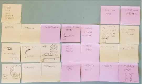
Innovation occurs the most when people work together and share ideas because when someone generates a new idea another person within the group can build off of it or use that idea as inspiration to create other solutions. There are different approaches that groups can take when brainstorming but the process remains as follows; for twenty to thirty minutes everyone on the project is allowed and encouraged to express any and all potential solutions to a given problem. All ideas are written on a large board and the goal is to maximize the quantity of ideas rather than the quality. By not worrying about the specifics of each solution the group was allowed to exhaust all solutions at the beginning of the project, even if some turned out to not be feasible or realistic. If quality was the focus of brainstorming, many ideas that are extraneous would have been discredited which would not be beneficial because sometimes the ideas that are “way out there” are a catalyst for a potentially great solution. Figure 13 below contains all of the Post-It Notes that were used during the ideation process.
Figure 13. All ideas generated during the brainstorming process, some containing sketches to explain general concept, most left ambiguous on purpose
Note that some of the ideas in Figure 13 are extreme and not within the scope of the project, including “make a new printer” and “fuse with high speed explosions”.
Brainwriting
Brainwriting is almost the opposite of brainstorming because in the brainwriting process, each team member spent around five minutes jotting down ideas in a notebook, including sketches and explanation if necessary. The focus of this exercise was to let each person come up with ideas devoid of influence from other persons. After the time limit was reached the notebooks rotated counterclockwise and another five-minute timer was set. During this second set of time each person added on to what was already in the notebook, providing sketches and notes when needed. The rotation continued until each notebook ended up back with its original owner. Two brainwriting sessions lasting fifteen minutes each were held, yielding more practical solutions than the brainstorming session including heat shrink bands on the inside or outside of the lattice and a combination of puzzle piece geometry and adhesive.
SCAMPER
SCAMPER stands for; substitute, combine, adapt, modify, put to other use, eliminate, and reverse/rearrange. This method is less of a standalone ideation process than brainstorming and brainwriting because the focus was on deriving new solutions by analyzing an already proposed solution and altering it using one of the previously mentioned factors. SCAMPER was utilized during all ideation sessions; for example, during the brainwriting session a solution was proposed which combined two joining methods, puzzle pieces and adhesive.
Description and sketches
AMPP produced multiple concept drawings for potential joining methods of the model’s three partitions. In each concept, the end faces of each component are joined together with the aid of a fixture that aligns the segments such that each component's mating surface is coincident with the adjacent partition’s joining surface. To create a permanent adhesion between multiple parts, a weld could be performed on each line of contact, or another an adhesive could be applied to each component's mating surfaces before joining the three partitions together. Nine concept models were generated from the ideation processes and compared in the following evaluation matrices. Some of the concept models had two variants due to two possible methods of adhesion: welding and adhesive.
Concept 1
Figure 14. Straight joint weld (1a) and straight joint adhesive (1b)
In concept 1a, the mating surfaces of each component are flat surfaces normal to the tangent of the arc. The mating surface terminates the outer wall, lattice, and inner wall thicknesses. After the faces of the components are placed together, a weld is performed down each of the joints. Concept 1b is a similar process, however an adhesive is applied to the mating surface before assembling the three components.
Concept 2
Figure 15. Puzzle piece weld (2a) and puzzle piece adhesive (2b)
For concept 2, each component contains a combination of multiple tabs and slots cut into the end faces. Each component's male tabs fit into adjacent component’s respective female slots. During this process, the part will be located cylindrically with the use of an assembly fixture. For concept 2a, a weld is applied to the part's three joints. Concept 2b is a similar process; however, an adhesive is applied to the mating surfaces before placing the three components together.
Weld or adhesive
Weld or adhesive
Concept 3
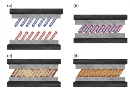
Figure 16. Full thickness outer shell - heat shrink (3a, left) and partial thickness outer shell – heat shrink (3b, right)
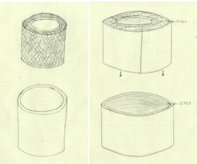
For concept 3a, the three components are printed without an outer shell. The end faces of each component are also flat like in concept 1, but a stainless steel band is heated and placed around the lattice. The band is the same height as the part and will be dimensioned to achieve the desired compressive forces on the lattice while obeying the engineering specifications. After cooling, the outer band’s resting state compresses the lattice, and the band will be designed so that the friction between the two prevents any relative motion. Concept 3b differs from concept 3a in that a thin portion of the outer wall is printed with the three components. The outer band, now a fraction of the full wall thickness, is heat shrunk around the three joined components.
Concept 4
Figure 17. Full thickness outer band (4a) and partial thickness outer band on both ends (4b) For concept 4a, each component is printed similarly to concepts 1 and 2, however the top and bottom portions of each component are printed without an outer shell. Two steel bands are heat shrunk over the two missing outer shell portions of the part. Each of the band's inner diameters are slightly smaller than the outer diameter of the top two portions of the part so that the bands can hold the printed parts tightly. Each band is the specified outer shell thickness and the same height as the two missing outer shell portions of the part. Concept 4b, is similar to concept 4a, however the top two portions of the components are printed with a thin outer shell of stainless steel. Two thinner bands, relative to the bands of concept 4a, are than heat shrunk over the part.
Concept 5
Figure 18. Hook joint weld (5a) and hook joint adhesive (5b)
Similar to the puzzle piece method, the hook joint method, concept 5, utilizes a male and female joining mechanism. Each component is printed with a vertical track of male teeth sequenced down a mating surface and a track of female teeth sequenced down the other mating surface. A male tooth is a hook intruding through the component’s entire thickness, while a female's respective tooth is hollow. The male teeth are meant to slide into and engage in the female teeth. For concept 5a, after the components teeth are latched together, a weld is applied down the part's three lines of contact. For concept 5b, an adhesive is applied to the end faces of each component, before assembling them together.
Weld or adhesive
Concept 6
Figure 19. Button joint weld (6a) and button joint adhesive (6b)
Similar to the puzzle piece and hook joint method, the button method incorporates a male and female joining mechanism. Each component is printed a male end and a female end. The component's female end face contains a lattice-less rectangular slot with two inner and outer shell fins extending off the base. Two square holes in the inner and outer shell female end, are located a small distance from the female's end face. The component's male end contains a small, square notch placed down the inner and outer shell. The notches are located a small distance off the male's respective end face. The edges of the male's inner and outer shell are cut at angles to pry the female end open. The inner and outer shell of the female slot deflect during the initial process of inserting the males face into the hole; however, the female's shell returns back into place after the wedges pop through the two small square holes.
Weld or adhesive
Concept 7
Figure 20. Threaded cap band inside and outside with weld (7a) and threaded cap band inside and outside with adhesive (7b)
Similar to Concept 4a and 4b, the top and bottom portions of each component are printed with a thinner outer wall thicknesses relative to the middle portion. The thin top and bottom outer wall portions are threaded with a lathe. Two stainless steel bands that have the same outer diameters as the top and bottom portion of the part are then internally threaded. The two bands are first screwed to the top and bottom portions of the part. For concept 7a, a weld is applied to the part's lines of contact. For concept 7b, an adhesive is applied to each end face of the three parts before assembling them together. In addition, adhesive is applied to the inner walls of each band before screwing them to the part.
Concept 8
Figure 21. Internal band weld (8a) and internal band adhesive (8b)
The respective components of this concept have multiple hollow tunnels running through the perimeter of the part. When the end faces of each of the components are placed together, the tunnels should be continuous around the part. Small stainless steel bands are first heated and then placed inside the continuous tunnels of the three components. After cooling, the internal bands shrink the part together tightly. For concept 8a, after the internal bands have tightly connected the three components together, welds will then be applied to the part's three lines of contact. In concept 8b, the heated internal bands are placed inside the tunnels and an adhesive is applied to the flat portions of end faces.
Concept 9
Six components are printed with small vertical holes spaced along the perimeter of three component's top faces, and three component's bottom faces. The holes along the perimeter of the components are placed along the outer wall sections of the components. The three components are placed together while the three bottom components are also placed together; however, the bottom components offset the vertical seems of the top three components. These top and bottom components are then joined together by dowel pins which align them axially.
Selection Process
Initial analysis on all possible ideas was conducted in order to create a list of three top concepts. The process started with creating a Pugh matrix to determine the weaknesses and strengths of each concept. After the Pugh matrix was completed, a weighted decision matrix was produced to compare the concepts to each other based off each concepts’ performance in certain criteria. Three models were selected from this process and will continue in the design process.
Pugh Matrix
In order to qualitatively rank each concept against one another a Pugh matrix was created with specific criteria and can be found in Appendix 4: Pugh Matrix. The following criteria were decided upon as a group and reflect the major requirements and concerns of the project: amount of parts, post processing difficulty, post processing time, tangential strength, post processing safety, part cost, quality of joined part, and temperature resistivity. The concepts that were added came from the ideation sessions and some new ones were added after. In order to compare each concept a datum needed to defined; a straight joint with a weld was chosen as the datum because each group member could easily understand and compare it to other concepts. Each concept was then analyzed one at a time for all criteria and compared to the datum, receiving either a “+ - better than”, “- worse than “, or “S - same” rank. There are multiples of concepts because after completing the matrix it was noticed that each concept could either incorporate a weld or adhesive to assist in the joining. For this reason, each concept was split into two separate concepts, one for a weld and one for an adhesive joining method. However, this does not apply to the heat shrink shells or bands.
Weighted Decision Matrix
The results from the Pugh matrix helped in estimating which concepts were the best but a weighted decision matrix was needed to derive a more definitive result. The layout was reversed from the Pugh matrix because in addition to providing a rank of each concept within each given criteria, each criteria was weighted as a percentage out of one-hundred. Criteria with higher percentage points were considered to be more critical to the project. Similar to the Pugh matrix execution, each concept was evaluated at each criteria receiving a value from one to ten. A ten meant that the concept would yield the best result for its given criteria. For example, the straight weld joint was given a ten for the criteria "amount of parts" because this method does not require any more parts than the project already specifies. On the other hand, the internal band with a weld was given a one for the criteria "post processing difficulty" because of the complexity of precisely navigating a band through the lattice structure and then performing a weld on the outer wall contact areas
between segments. For the other criteria, a higher tangential strength, less post processing time, less cost, higher safety, higher quality, and higher temperature resistivity all correlate to a higher numerical value. After all criteria were considered, the values were multiplied by the weight of their respective criteria and added together to create an arbitrary number. After all concepts were analyzed their corresponding arbitrary numbers were sorted to determine the highest ranking concept. The full values of the weighted decision matrix can be found in Appendix 5: Weighted Decision Matrix. The top three concepts were pulled directly from the results and are as follows: heat shrink outer shell, button with a weld, and puzzle piece with a weld. Note that the top two concepts based on the weighted decision matrix are both heat shrink methods, only varying in the thickness of the unprinted shell, so they were considered to be one concept.
Description of Top Three Methods
Outer Shell Heat Shrink
The heat shrink shell is a method in which only the inner wall and lattice are printed. The outer shell that will be heat shrunk over the printer part must be made separately using other methods. The first method that may be used is called drawn over mandrel (DOM). The process starts with a coil of steel that is cut and then the plate is pulled over a series of rollers to form a tube that is sealed by an electronic resistance weld. This tube is then placed around a mandrel with the leading end crimped so that it may be gripped and pulled through a die. A better visual of this process is in Figure 23.
Figure 23. Drawn over mandrel (DOM) method (16)
The die combined with the mandrel help to create a tube with a specific outer diameter and wall thickness. This DOM tubing would be purchased from an outside source due to the tooling required in this method. The second method in which the shell may be produced is by purchasing metal stock and turning it down on a lathe to the necessary diameter and wall thickness.
As mentioned in the previous section, the heat shrink shell can either be the same wall thickness as the inner, printed wall or it can be a fraction of the thickness. This shell will be sized such that its inner diameter is equal to the outer diameter of the printed parts. In order to expand the material,
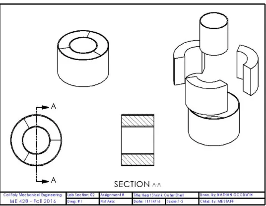
the shell will be placed in an oven and allowed to heat until it has expanded enough in all radial directions to easily slide over all of the segmented parts. A fixture will be used to locate all three printed parts so that the heated shell can be placed over the printed parts as concentrically as possible. The shell is then allowed to cool at room temperature so that it shrinks itself over the parts evenly. Figure 24 below shows a layout drawing of the final part.
Figure 24. Layout drawing of the heat shrink outer shell joining method. This drawing is based on a full thickness band
Note that if the outer shell can be easily fabricated or purchased then an inner shell may be used to help increase the strength of the completed part.
Button with Weld
The button method can be understood by the clipping mechanism of buckle clips, seen in Figure 25 below.
Figure 25. Buckle clips found on backpacks, fanny packs, and various other gear (20) The figure above can be viewed as a top down view of the final part with the inner and outer walls corresponding to the two prongs of the buckle. One end of the segment would have a male component which slides into the female component. For this project however, instead of the male component deflecting inward, the female part would deflect outward and the male part would remain rigid. Multiple of these "buttons" would be placed vertically along the edge of each segment to create a stronger total hold. After all buttons are clipped into place a weld would be applied along the seam where the two components meet. Figure 26 below is a layout showing how the parts would be assembled (vertically sliding) and the geometries of each segment.
Puzzle Piece with Weld
The puzzle piece method is another geometric fitting but secures differently than the button. Each segment is split into a male and female end that fit into each other; however, instead of each protrusion appearing like a piece from an actual puzzle set, the pieces are straight horizontal cuts. Figure 27 below shows how the puzzle pieces can slide together radially at one time. Once all three pieces are fitted into one another, a weld would be applied, following the line of contact between both segments.
Figure 27. Layout drawing of puzzle piece joining method
Justification of Top Three Methods
Sound engineering judgment was used during the decision making process; the following analysis provides concrete explanations as to why each of the top three concepts are valid and the best ones to continue analyzing.
Outer Shell Heat Shrink
This method is different than all of the other methods because there is no need for a weld since the outer shell is made as one piece and does not need to be joined. This seamless surface also helps to reduce the amount of post processing time since there is no need to lathe off residual material from welding. A basic calculation was performed to determine the approximate safety factors based on both a fully and partially thick outer shell. The outer shell was treated as carrying all of the load (this calculation assumed that only an outer shell would be fabricated). The following Table 2 shows the yield and ultimate tensile strengths used for stainless steel 316L.
Table 2. Yield and ultimate tensile strength properties of stainless steel 316L from two different sources
AK Steel (21) Lincoln Electric (22)
σy 42 30 KSI
σu 81 78 KSI
The calculation, see Appendix 6: Hand Calculations for the full solution, for a full thickness outer shell came out to a maximum force of 1500 lbf, equating to a factor of safety of 3. The partially thick shell has an approximate factor of safety of 2.2. If an inner shell were to be fabricated the factors of safety would both increase since the inner shell would assist in carrying the load.
Button with Weld
The button method has benefits since there is no need to fabricate any more parts than those that are printed and the assembly process is quick. Similar to the puzzle piece method a weld would be applied along the contact faces of each segment which would serve as the main source of strength. An analysis was performed on the possible shearing of the buttons as they are slid into place as well as the strength of the partially thick inner and outer wall. The factor of safety for possible shearing is 2.3 and the 1.1 for the walls. The full calculations and assumptions can be found in Appendix 6: Hand Calculations.
Puzzle Piece with Weld
The puzzle piece method is similar to the button method because they both mainly assist in locating the pieces together so that a fixture is not needed to hold them together when the weld is applied. It has the same benefits as the button method but fits radially which may prove to be easier than the parts fitting vertically. However, the heat affected zones due to welding will be the weakest areas of the part. For this reason, the puzzle piece method may possibly be combined with the heat shrink method to remove the need for a fixture to locate the parts while the shell is shrinking over them.
Preliminary Plans for Construction and Testing
The three top designs selected from the decision matrix will advance into the manufacturing stage of the design process. The steps of the manufacturing process lead up to a print of the final part on the SLM 125HL machine. Since the resulting part will be larger than the SLM 125HL’s build volume, the manufacturing process will achieve the ultimate goal of this senior project. The manufacturing process will begin with printing prototypes on a plastic extrusion printer due to the quick print durations and low part cost. Plastic models will reveal information that may not be evident from the CAD models, which will lead to improvements in the geometry of the CAD model. The concepts will be iterated on the plastic extrusion printers until the joint geometry is
nearly finalized. The joint geometry will be implemented into a flat joint that can be tested for the desired loading requirements. AMPP will request some of the flat joint geometries to be printed on LLNL’s SLM machines while the test and assembly fixtures are fabricated. Around the same time that the fixtures are created, any non-printed parts pertinent to the final design, such as the heat shrink outer band, will be sourced and machined. Finally, all of the printed parts, non-printed parts, and an assembly fixture will be used in the assembly process to create the joined part.
Extrusion Printing
Additively manufacturing stainless steel prototypes is an expensive process that should be saved for some of the most refined models. A single print with an SLM 125HL can take approximately nine days, which compared to the length of the senior design process, is an exceptionally long print time. To further discourage printing parts on the SLM 125HL machine at Cal Poly, the machine is not currently operational and will tentatively remain inoperable until January. For these two reasons, concepts will initially be printed using one of the LulzBot Taz 6 thermoplastic extrusion printers in the Wind Tunnel Laboratory at Cal Poly, seen in Figure 28 below. AMPP has experienced print durations of approximately eight hours with this particular printer, and this will allow for about one iteration per day. Iterating the geometry with the extrusion printer will minimize the amount of models that will be printed on the SLM machines.
Figure 28. LulzBot TAZ 6 (23)
Flat Joint Design and Testing
Once the geometry of the joint is finalized on the extrusion printers, the joint geometries will be implemented on a flat joint rather than a curved joint. Approximating a curved joint as a flat joint is valid because an internal tangential force acts in the direction of the flat joint. The internal force
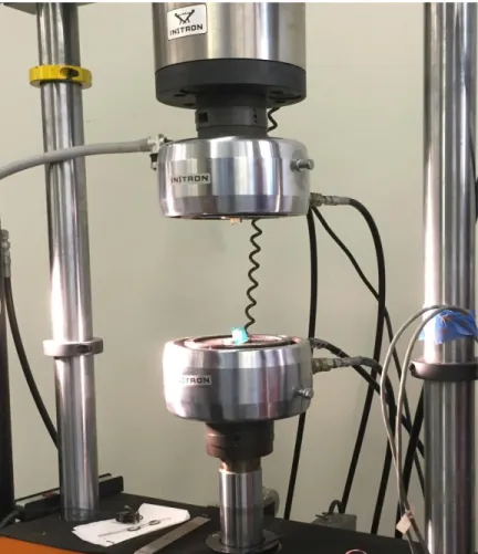
that the joint will be designed for can be applied in a tensile testing machine, such as the Instron in Figure 29. Testing just the flat joint reduces costs in the printing process since less material would be printed and the print duration would be shorter. The results obtained from testing flat joints would be analyzed in order to decide on the best joining method for the final part, which would be printed on an SLM machine.
Figure 29. Tensile testing Instron in Cal Poly’s Composites Lab
Fixture Fabrication
The assembly technique of the final part would require a fixture, especially if the segmented parts need to be welded together. It is necessary for the assembly fixture to be rigid, relative to the part, to prevent warpage during either the heat shrink or welding process. The assembly fixture would be lathed from metal stock to either match the inner or outer diameter depending on the joining method. This would be fabricated in parallel with the testing of the flat joint and the printing of the final part to ensure that the fixture is functional before the segments are ready to be joined. A test of the functionality of the assembly fixture may include joining plastic parts before the final parts are joined.
Another fixture that is likely to be fabricated is a testing fixture. The purpose of the testing fixture is to test the maximum, internal, tangential force that the joined part can withstand. The test fixture
would be two identical attachments for the Instron jaws that would use hemi-cylindrical extrusions to pull the cylinder apart from the inside. A hemi-cylindrical extrusion on each attachment would fill the inner volume of the joined part. This would also be fabricated in parallel with the flat joints and the printing of the final part.
Heat Shrink Band Fabrication
Two methods for creating the heat shrink bands have been proposed. The first method would require AMPP to find a source for DOM tubing since the DOM process cannot be conducted at Cal Poly. If DOM tubes cannot be obtained in the particular size required for this project, the inner diameter, outer diameter, and length could be changed on a CNC lathe at Cal Poly. Lathing tubular stock is the second method to create a heat shrink band. Although the first method may include lathing DOM stock to the target dimensions, the second method focuses on lathing any tubular stock to the target dimensions. The stainless steel tubular stock required is 8” Schedule 100, which is about 7.5 times thicker than the outer shell (24). Lathing the tubular stock to the target diameter and thickness would require most of the material to be removed and consequently increase tooling costs and operation time. Sourcing DOM tubing that is a similar size to the outer shell may be preferable, but further research will be conducted.
Final Part Fabrication
The final part will ideally be printed within the SLM 125HL at Cal Poly in three segments. If external parts are needed, such as the heat shrink shells, they will be sourced and fabricated prior to the print of the three segmented parts. In the event that the SLM 125HL at Cal Poly is not operational, the parts will be requested to be printed at LLNL and shipped to Cal Poly. AMPP will be conducting the final assembly with the assembly fixture. The general assembly procedure is known, but depending on which concept performs best in the flat joint tests, the procedures will change. For the heat shrink fit shell concept, the temperature ranges and dimensions of the shell prior to the shrink fit are unknown. Also, the final dimensions of the fixtures are still unknown. The entire process will be extensively documented and presented to LLNL.
Safety Hazard Identification
Safety is key to a team’s happiness and productivity. Cal Poly and AMPP plan to contribute to a safe and healthy environment. One of the biggest goals AMPP tries to achieve is maintaining a safe workplace environment for its team members and technicians. Efforts will be made to reduce the amount of hazards to keep AMPP team members safe. Professional technicians will assist AMPP with the operation of the SLM machine and post-processing machines.
Mechanical
o Part Kinetics
Part may fall off lathe and cause injury. o Failure
o Lacerations
Surface finish of printed part may be rough, and cause lacerations to hands if not handled with gloves.
Connection points of the axisymmetric part may cause pinching if not handled with care.
Heat
o High Degree Burns
High degree burns can occur from heating treating of the metal bands if safety precautions are not taken. Serious burns can occur if printed parts are immediately handled.
o Explosion
An explosion may occur if the SLM printer is not properly cooled, and ventilated.
Electrical o Shock
Shock may occur if the SLM machine, or person is not grounded. Shock can occur if a liquid spills onto the SLM machine while it is running. It may also occur if the axisymmetric part is electrically conducted.
o Fire
A fire may occur if the SLM machine overheats.
Chemical o Toxic
If the metal powder is ingested, may require hospitalization.
Ergonomic
o Human Error
If machines are not properly operated, serious death or injury may occur. o Noise
Final Design Details – CDR
Continuing onward from the Preliminary Design Review, the top three methods were further analyzed to converge on a single design. This section of the report will describe the design of the joint geometry and joining method that AMPP has devised to meet LLNL’s requirements. The final design incorporates ideas from the initial concepts to assist in the locating of the parts when joining. The report further justifies the use of these design decisions based on engineering concepts and feasibility. AMPP created the final design in SolidWorks and produced engineering drawings to convey dimensions to the manufacturing lead. The dimensions of the part originated from the supporting data and are included last in this section. Any alterations to the design occurring after the Critical Design Review will be stated in the following section, Final Design Changes.
Design Description
Final Part for CDR
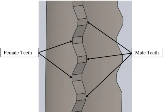
The final design builds upon and combines the best aspects of each of the top three designs from the Preliminary Design Review. Drawing from the puzzle piece idea, each segment will be printed with teeth at the end of either face such that they will align in the axial direction quicker than if the edges were flat. This geometry feature has no additional cost since total volume of printed material does not change, only the pattern in which the material is printed changes. This feature will be referred to as teeth where each part has three male teeth that joins the two female teeth on the adjacent part. Male and female teeth are shown in Figure 30 below.
Figure 30. View of the three male teeth and two female teeth at the end of each printed part Another major feature of the printed part prevents movement in the radial direction and holds the segments together rigidly. This feature will be referred to as the collar since the design is similar to a shaft collar. The collar design involves printing an extra 15mm of solid material to the top and bottom of each segment along with a pilot hole perpendicular to the face of the mating surface, shown in Figure 31. In post-machining processes, the pilot hole will be drilled, counter bored, and tapped in order to bolt the parts together with ¼-28 screws. Once the parts are joined together and turned, the heat shrink processes can be performed to fit the inner and outer bands. The final machining operation will turn the assembled part to the final inner and outer diameter and part off the collars in the lathe. Sufficient clearance will be printed between the bolt and the lattice to allow for a smooth part off operation since there will be no interrupted cuts or changes in density of the material being parted.
Figure 31. Collar added to the top of the printed part.
Test Piece Assembly
To prove the results from Appendix 6: Hand Calculations of the Minimal Band Thickness, three different test assemblies will be manufactured using three sets of inner and outer bands with varying thicknesses. The first band thicknesses will be machined to the large value of 1.8 mm while the second set of bands will be machined to the nominal value 1.7 mm thick and the third set will be machined to 1.6 mm thick. The shell thickness of each set is 0.2 mm, 0.3 mm, and 0.4 mm, respectively to maintain a total wall thickness of 2 mm. The final height of each set, which is equal to the height of the lattice, is 20 mm with a 15 mm layer of solid material between the sections so that each segment of each set can be printed vertically on top of each other. Figure 32 below shows a cross section of what one side of this test piece assembly looks like. Note that the radial scaling of the figure is 10:1 while the axial scaling is 1:1 so that the cross section can be clearly seen. Also, the axis of revolution is not shown on the drawing. The bottom set consists of the 1.6 mm bands and the 0.4 mm printed shells. The middle set consists of the 1.7 mm bands and the 0.3mm printed shells. Finally, the top set consists of the 1.8mm bands and the 0.2 mm shells.