Validation of Agile Workflows using Simulation
Kai Jander, Lars Braubach, Alexander Pokahr, and Winfried LamersdorfDistributed Systems and Information Systems Computer Science Department, University of Hamburg
{jander | braubach | pokahr | lamersd}@informatik.uni-hamburg.de
Abstract. Increasing automation of business processes and industrial demand for complex workflow features have led to the development of more flexible and agile workflow concepts. One of those concepts is the use of goal-oriented workflows, which rely on ideas derived from agent technology like describing the workflows based on a goal hierarchy. While this reduces the gap between business view and IT view and allows for easy implementation of contengencies, the concepts have greater concep-tual abstraction obscuring the control flow and reducing the ability of workflow engineers to identify specification flaws in the workflow. This paper shows an approach to address this problem by presenting a system for testing and validating workflows within a specified parameter space. The system allows the definition of test cases (scenarios), each of which contains parameter states applied during workflow execution. The work-flow engineer can define a set of scenarios for a workwork-flow testing specific situation that are likely to occur during operation or are otherwise in-teresting corner cases, allowing automated tests and correction of faults before deployment of the workflow in production environments.
1
Introduction
Business process management (BPM) is considered a very promising strategy that helps in aligning companies towards effective and efficient business opera-tion [1]. This is mainly achieved by completely thinking in terms of processes, which means that even the structure of organizations has to follow the processes and cannot be kept in a functional orientation. The vision of BPM assumes that processes can at least partially be automated, monitored according to key per-formance indicators (KPI) and continually improved or even renewed according to the measurement and defined KPI targets. It becomes clear that this vision heavily depends on adequate IT means supporting these tasks, which e.g. man-ifests in the development of workflow notations and management solutions.
One fundamental problem with existing solutions that has been experienced in practice is that modelling notations like event process chains (EPCs) or the business process modelling notation (BPMN) are activity oriented and thus fo-cus heavily on the ordering and conditions of activity execution. This leads to a particular neglect of the underlying process motivations, which are only implic-itly existing during workflow elicitation. Without this so called workflow context
perspective [2] it becomes e.g. difficult to optimize the processes because it can-not be easily afforded why specific activities in the workflow exist and if they e.g. could be completely cut out. These observations led to the development of more abstract, flexible and agile workflow concepts. While these concepts contribute to closing the gap between business view and IT view, the greater conceptual abstraction also partially hides the complexities of all possibilities of the ex-act runtime control flow and reduces the ability of workflow engineers to easily identify specification flaws in the workflow.
In order to equip a workflow modeller with a toolset to better understand the possible runtime behaviour of more abstract workflows, simulation and validation gain importance. In this paper a new concept and implementation for a simu-lation based validation approach of workflows is presented. It allows to specifiy execution scenarios and automatically evaluate them with respect to expected process outcomes. The approach does not depend on the concrete workflow no-tation in which processes are described but only assumes that specific workflow management facilities are available. Thus, the approach is viable for validating traditional e.g. BPMN based workflows as well.
The rest of the paper is structured as follows. In Section 2 related work with respect to verification and validation approaches of workflows is discussed. Thereafter, in Section 3 the concept of the new simulation based validation approach is presented. Its implementation and usage is explained in Section 4 and the usefulness of the approach is further illustrated by an example application taken from our industry cooperation partner Daimler AG. The paper concludes with a summary and a short outlook on possible future enhancements.
2
Related Work
Literature and practical application contains a large variety of validation and verification approaches for workflows. They can roughly be divided into two cat-egories. The first category consists of formal static analysis of the workflow model to identify conceptual or implementation flaws. The second category comprises of validation using simulation-based execution of the workflows.
Formal verification approaches of workflows apply a number of techniques, such as propositional logic [3], model verification [4] and graph reduction [5]. The approaches are usually either based on a formally well-defined representation like petri nets [6] or attempt to translate workflows implemented in different repre-sentation like EPCs or BPMN into a more approachable form from a formal perspective [7]. While formal verification has the distinct advantage of guar-anteeing correctness within the given constraints of the verification approach, translation of workflow models weakens this guarantee unless the translation itself is formally proven correct. Verification also requires a well-defined lan-guage with well-known properties, however, some lanlan-guages used in practices lack these criteria. For example, many parts of BPMN in its current form are left ambiguous and underspecified. The reason for this usually is not negligence but an attempt to bridge the gap between the technical side and the business
side of workflows. Parts of the specification are deliberately left fuzzy with am-biguous semantics which enables the use of the specification in informal and non-technical settings. However, some of the issues of ambiguity are currently addressed in the upcoming version 2.0 of the BPMN specification.
Furthermore, verification approaches are often quite limited on what they can guarantee. For example, while there are excellent approaches to guarantee correctness of the workflow diagram like ensuring that branches in the workflow are terminated with a correct join element, they are generally unable to verify non-trivial semantics like task instructions written in a programming language or complex runtime behavior.
This problem can be approached by the validation techniques in the second category. Instead of statically analyzing the workflow models, the workflow is ex-ecuted in a simulated environment which attempts to imitate the environment in which the workflow is planned to be deployed. Examples of this approach in-clude a variety of tools like LSIM [8], iGrafx Process [9], the Corporate Modeler Suite [10] and the ARIS Toolset [11]. The tools generally target specific work-flow notations such as BPMN to combine static analysis described above with simulation. Furthermore, the focus of the tools tend to be performance measure-ment and optimization. For example, the ARIS Toolset offers a large number of features used to measure operating and performance figures of the workflow during simulation.
In contrast, the focus of our approach has primarily been the validation of the workflow using predefined test cases centering around expected real world scenarios. The disadvantage of this approach compared to verification is that the correctness can only be ensured within the given conditions of the test. Since the number of configurations in any non-trivial workflow is very large, exhaustive search becomes infeasible. This means the approach can only validate the workflow to a certain degree and may not detect all errors present. The advantage of the approach is that the complexity of the workflow language is irrelevant to the test as long as there is a workflow engine capable of executing the workflow. Furthermore, the current approach uses few assumptions about the workflow itself allowing the system to be useful for different kinds of workflow notations. While the focus has been on validation of workflows, the approach can be extended to include simulation of the environment in which the workflow is running but which is, by itself, not part of the workflow. This includes logistic operations, production machinery, behavior of workflow participants and market influences. This allows additional applications beyond workflow validation like workflow optimization similar to the tools mentioned above.
In the following we will present this simulation-based testing approach which uses simulation of workflow participants to validate the correctness of workflows. The focus will be on goal-oriented and agile workflows, however, as mentioned, the approach itself can at least partially be applied to any workflow which relies on interaction with participants.
3
Validation Approach
Due to its application in industry and business automation and intense research interest, a great variety of workflow approaches and notations are available. While our validation approach is designed to be generic, two kinds of notations in particular were the focus of the project. The first is the well-knownBusiness Process Modeling Notation(BPMN, see [12]), which has been extended with task and edge annotations, allowing it to be directly executed by an interpreter. While BPMN does not strictly define semantics and contains certain ambiguities, most BPMN elements can be interpreted in a straightforward fashion. Furthermore, the updated standard BPMN 2.0 specifically aims to provide execution seman-tics. Eventually, the interpreter aims to support these semantics, however, for now it supports a restricted set of BPMN where the semantics appear to be clear and are ultimately defined by the implementation of the interpreter as included in the Jadex platform.
In addition, an additional notation called Goal-oriented Process Modeling Notation (GPMN, see [13]) has been developed, which allows the description of goal-oriented workflows using goal hierarchies. Workflows implemented us-ing GPMN are converted into BDI agents at runtime. BDI agents are based on the Belief-Desire-Intention model where beliefs represents the agent’s current knowledge about the world, goals represent its abstract desires of what should be accomplished and plans represent concrete intents of the agent with explicit actions the agent follows (see [14]). The goals used in GPMN workflows are di-rectly converted to goals of the resulting agents while the plans that are on the leaf nodes of the goal hierarchy are represented by small workflow fragments im-plementing the concrete steps in BPMN. During execution, the GPMN-derived BDI agent employs a BPMN interpreter to execute the fragments as plans of the agent.
In addition, GPMN workflows contain a context which represents the current workflow state. This context is used as the belief base of the converted BDI agent at runtime. This context may be changed during execution of the workflow, either directly by the workflow itself or by effects outside the workflow. Changes in the context can directly affect the workflow and thus the agent behavior by influencing adoption, persuit and rejection of goals.
3.1 Goals of the Test System
In practice, workflow engineers currently often validate workflows by manually performing tests of common scenarios which represent typical business cases for the workflow. For example, if the workflow involves production preparation for a new vehicle line at Daimler, the workflow engineer executes the workflow and then plays out the scenario as it is typically expected to occur at Daim-ler. This involves providing various production issues such as faulty parts. The information is provided to the workflow in the usual fashion as if the workflow is used during production. The behavior of the workflow is then monitored and irregularities are noted and addressed during reengineering.
As a first step to provide better testing facilities for GPMN, we aim to provide a test system which automates the process the workflow engineers are used to and enable them, through automation, to increase test coverage and test a greater number of test cases which would usually be omitted due to time constraints. The general idea is to make workflows executable in a similar way as test cases for a normal programming language. As such a normal test case, also a workflow test case needs to be specified in terms of inputs and expected outcomes. Given these information are available, a test system can automatically executed the worfklow and validate its results. In addition, workflows in the real world may last a considerable time hindering the efficient execution as test case. In order to alleviate this problem, the test system will employ simulation techniques for an execution that is ’as fast as possible’, i.e. the processing power and not waiting times in the process determine its execution speed.
The goal of the current system is neither to provide a full formal verifica-tion through model checking nor is it to include complete test coverage since the complexity explosion with non-trivial workflows would impede its usefulness in practice. Since the system is part of a system dealing with business process management, it needs to be accessible to people without a technical or formal background such as business users. It allowss business users to test identified domain scenarios in a sensible way and in this helps increasing the test cov-erage of the workflows. The system is therefore more closely resembling other test techniques for general purpose programming languages such as unit tests. However, it is more specifically focused on aspects of workflow management and the workflow language GPMN.
3.2 Requirements for Automated Testing
Both GPMN and BPMN offer language features which allow the workflow engi-neer to implement different execution paths or branches. In the case of BPMN workflows, this is accomplished using the gateway element, which can split the control flow into either multiple paths executed concurrently or diverts the flow towards one of multiple possible control flow edges. The implementation of ex-ecution paths in GPMN workflows is more subtle and indirect. Depending on the state of the workflow context, different goals may become active resulting in the execution of different BPMN plans. This control flow subtlety of implicit control flow paths in GPMN workflows increases the difficulties of a workflow en-gineer to accurately predict possible runtime execution paths and is the primary motivation for our validation approach.
The core idea of our approach towards validating such workflows is the use of automated tests. This implies that the system should be able to execute such workflows without user intervention once the test has started. Since only the most trivial workflows can be automatically executed merely using a workflow engine and since most workflows require interaction with workflow participants or automated systems while running, additional system components are neces-sary beyond the workflow engine itself. Moreover, while most workflows specify a range of possible responses by workflow participants, they generally do not
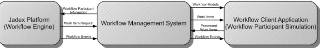
Fig. 1.Structure of the proposed test system
specify which responses will influence workflow behavior, thus necessitating the specification of additional information by the workflow engineer before the test. Consequently from a simulation perspective, a workflow engine executing a workflow is not a viable simulation model for validation workflows since it lacks sufficient detail even for simple automated execution, much less being a realistic representation of a production environment using workflows. Therefore it is necessary to add additional components to the system which are equivalent or at least sufficiently similar to their production counterparts to represent an adequate model of a workflow in production use (see Figure 1).
3.3 Workflow Management System
One component which is routinely part of workflow systems in businesses is a workflow management system(WfMS). The task of a WfMS among other things is to facilitate interaction between workflows and workflow participants. This is generally done by providing work items, which are packages generated by the WfMS on behalf of the workflow containing all the information needed by the workflow participant to accomplish their part of the workflow. The WfMS then distributes the work items among the workflow participants using a variety of approaches such as roles. As a result, the simulation model of a realistic test system needs to include a WfMS which accurately represents a WfMS used in production.
Work items generated by the WfMS not only include information for the workflow participant but often ask the participant to gather and provide external information like customer data or processed documents for the workflow. This is defined in the workflow with the specification of typed parameters in tasks which generate work items. This information often influence further behavior of the workflow at critical junctions like BPMN gateways or goal deliberation. Since real workflow participants are not available during test runs, it is necessary to simulate their actions, including the supply of external information.
Work items are generally retrieved and processed by the workflow participant using a workflow application client interacting with the WfMS. The work items are retrieved, processed by the workflow participant and finally comitted back to the workflow management system, thus allowing the workflow to continue executing. In order to simulate this behavior, the workflow client application used by the workflow participant needs to be replaced with an automated workflow client application which simulates its behavior and the behavior of the workflow participant.
3.4 Client Application
The simulated workflow application client is required to provide the information which is normally provided by the workflow participant. As a first step, the client identifies the workflow tasks which generate work items and require the workflow participant to provide information in the form of work item parameters by examining the workflow model and the models of possible subprocess, such as BPMN workflow fragments in case of GPMN workflows. Parameters are typed and thus already have a limited parameter space. However, this parameter space in cases such as string types is extremely large, precluding an exhaustive test of the full parameter space. Since a complete verification of the process using this approach would also require to test the cartesian product of the parameter space of all parameters provided by the workflow participant, the complexity of such a verification exceeds the limits for a practical test and cannot be considered a useful approach.
As a result, it is necessary to restrict the scope of the test to only include the part of the parameter space which includes the most promising cases, such as cor-ner cases of branching decisions and validating the workflow only for those cases. Since the test cases cannot be identified automatically, the workflow engineer has to define the parameter space that needs to be tested. This is accomplished by the system by allowing the workflow engineer to define test scenarios. Scenar-ios represent a subset of the full parameter space of the workflow participant interaction with the workflow. For each parameter in the process the workflow engineer can define a set of parameter values which are used to process work items while the workflow is executing. If the workflow engineer defines multiple values for each parameter within the same scenario, the cartesian product of those values is tested at runtime.
The workflow engineer can define multiple scenarios for each workflow. When the test is started, the first scenario is selected and the workflow is started repeatedly, once for every element of the cartesian product of the parameter values in that scenario. Once the scenario finishes, the next scenario is selected until all scenarios have been tested. An event log is kept during each execution, recording notable events occuring at runtime for later analysis. The workflow engineer can use this log to identify errors in the workflow and correct them before the workflow is used in a production system. In addition, a test report is generated and can be reviewed.
Errors in the workflow can be unrecoverable states of the workflow like a raised exception during execution or unintended behavior of the workflow such as performing a faulty execution order of tasks. In additions, it is also considered to be an error if the workflow returns the wrong results or reaches the wrong internal state. Since the workflow engineer has to be informed about such errors occuring, monitoring of the workflow is required. On raised exceptions, executed steps of the workflow and state changes the workflow engine can generate a workflow event which is passed through the WfMS to the client application for review by the workflow engineer. It would also be desirable to allow the workflow engineer to define a validation function which receives the information provided
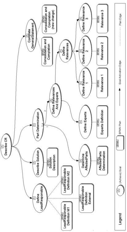
Fig. 2.The workflow tree model used on the client side of the testing system
to the workflow and the final state and result of the workflow allowing the system to automatically evaluate whether a test was successful.
The following section will elaborate on the individual parts of the testing system. It will include an overview of the workflow management system and provide details about the simulated workflow client application and how the workflow engineer can define the parameter space subset for each scenario.
4
Simulation System Components
As mentioned in the previous section, the testing system requires a minimum of three components. In order to execute the workflows themselves, a workflow engine is needed, a workflow management system is needed for work item man-agement and user interaction and finally there needs to be a special workflow application client which simulates user behavior.
Since GPMN workflows are translated into BDI agents with BPMN plans and thus require a workflow engine which can execute both, the Jadex Active Components Platform [15] has been chosen as the execution environment for the workflows. The platform is not only capable of executing GPMN-derived BDI agents but also includes a BPMN interpreter which allows the execution of BPMN processes alongside agents. While the platform is able to execute stan-dalone BPMN processes as active components, BPMN workflow fragments which represent GPMN plans are executed with a special BPMN plan interpreter, which allows the BPMN workflow fragments to access the GPMN context in the form of the agent belief base.
4.1 Workflow Management System Architecture
A primary function of a workflow management system is the generation and dis-tribution of workitems which is triggered by user tasks in workflows. Workitems
instruct a workflow participant, such as an employee involved in the process, to perform a certain task for the workflow. The workitem itself does not always specify the exact person performing the task in the workflow model since such a specification is not always necessary if the task can be performed by multiple people. In fact, such a direct assignment of tasks can be problematic due to dynamically changing conditions with regard to the status of persons, such as vacations and employee fluctuations. Therefore the assignment is usually done at runtime using specific criteria. A common way of solving the problem is to assign the task to a specific role in the workflow model and letting either the WfMS or the employees themselves do the final assignment to a specific person depending the person being able to fulfill that role.
Since workitem assignment is part of the runtime behavior of workflows, this aspect alone requires the inclusion of the WfMS in the simulation model to accurately reflect that behavior during simulation. Additionally, there are further WfMS runtime behavior that should be included in the simulation model, such as workitem access rules and workflow instantiation.
The implemented WfMS is implemented largely based on the reference model of the Workflow Management Coalition [16]. It uses the Jadex platform with Jadex platform services implementing the services required for the system which will be explained in further detail in this section. In addition, the system includes three interface agents which realize a message-based interface with workflow application clients.
The services of the WfMS are divided into internal and external services, the former implementing the actual functionality of the WfMS while the latter, rep-resented by the agents, act as an interface which can be used by workflow client applications to connect with the WfMS. The Jadex platform itself represents the workflow engine and enactment service of the WfMS by providing the necessary support for instantiation of workflow models.
Workflow models are managed by the WfMS using a process model repository service. This service supports the addition and removal of process models by employing the Jadex library service which allows Jadex to dynamically load new models, resources and executable code by linking directories or jar-archives. In addition, it offers access to workflow models for workflow client software, which is a necessity for the testing system since the simulated workflow client application requires the workflow model in order to identify tasks in the workflow which require interaction with a workflow participant.
The Authentication, Access Control and Accounting (AAA) Service of the WfMS provides additional workflow participant-centric services. This includes access control to workflow services and a role management system which allows the WfMS to associate work items with workflow participants. Each task which generates work items can assign a role to the work item, restricting this work item to workflow participants who represent that role. Work items without a designated role become available to any workflow participant connected to the system.
Fig. 3.Procedure for testing workflows
The external services of the WfMS consist of three parts. The first service is theworkflow client interface, which manages the work item queue and distributes work items to connected clients. The second service is theprocess definition in-terface, which provides access to the process model repository by allowing clients to add and remove workflow models and accepting requests for workflow models. Finally, the administration and monitoring service offers access to administra-tive and monitoring functions. The monitoring functions are especially critical for the testing system since they provide feedback regarding events happening during workflow execution.
This system provides a similar functionality to a workflow system in produc-tion use. In addiproduc-tion to this basic system, a workflow applicaproduc-tion client which simulates the behavior of workflow participants is needed to create an automated testing system which can execute tests of workflows without user intervention. This client is implemented as a BDI agent which connects to the three external service agents to the WfMS. The agent provides a user interface to the work-flow engineer, which allows them to open the desired workwork-flow model which is retrieved from the WfMS.
As a result the WfMS forms an integral part of the simulation model by simulating the WfMS used in a production system. This is especially impor-tant if a specific workitem assignment based on roles or similar concepts is part of the validation parameters for the workflow. In addition, potential effects of workitem processing such as multiple available workflow, workitem access rules and communication delays can be tested.
4.2 Client-side Workflow Model
Since it is desirable for the workflow engineer to gain an overview of the parts of the workflow which are relevant to interaction with workflow participants, the client agent uses the workflow model to generate a tree representation of the workflow model which can be seen in Figure 2. The tree consists of a workflow node as the root node, which represents the workflow originally opened by the workflow engineer. If a workflow contains sub-workflows like BPMN plans, the children of its workflow node can include further workflow nodes representing those sub-workflows.
The sub-workflow graph of a workflow can contain cycles, for example, when a sub-workflow uses its parent as a sub-workflow. This would suggest a graph
representation to be the natural form for representing the workflow structure. However, cycles in the workflow graph are rare in practice and a workflow en-gineer would expect a tree form rather than a graph. Therefore the tree repre-sentation is more desireable, nevertheless the special case of a cyclic workflow structure should be supported. This problem is solved with the use oflink nodes. If a particular sub-workflow is found again after having been found before, it is represented as a link node in the tree. This link node is a simple reference to the first occurance of the sub-workflow in the structure and no further expansion of the tree is done beyond this reference to avoid endless expansion.
If a workflow node is a BPMN workflow or workflow fragment its child nodes can, in addition to sub-workflow nodes, containtask nodeswhich represent tasks containing interaction with workflow participants. Lastly, the children of task nodes are parameter nodes, which represent typed parameters which would or-dinarily be provided by a workflow participant.
4.3 Scenarios
The tree structure of a modelled workflow is presented to the workflow engineer in graphical form in the user interface. This allows them to define scenarios. Scenarios consist of sets of input values for each parameter of the workflow, defi-nition of data collected from the workflow during the simulation and a validation function which is used to evaluate the success of the test and generate a report for the workflow engineer. Figure 3 demonstrates the use of scenarios in the full test procedure.
For each of the input parameters, the workflow engineer can add multiple values depending on the type of the parameter. The cartesian product of the input values in the scenario is used to create tests for the workflow which means that a minimum of a single value for each parameter is required for the scenario to generate at least a single viable test.
The workflow engineer can also select what is monitored during execution. This can include output values of the workflow, its final internal state, exceptions and the task executed. These values are passed to thevalidation function after execution to determine whether the test was a success and to generate a useful report. The validation function is also defined by the workflow engineer and included in the scenario.
Multiple scenarios can be defined for each workflow which can be automat-ically executed in succession. The total number of required test runs of the workflow are reported to the workflow engineer while assembling the scenarios. Since the cartesian product of multiple parameter values in a scenario quickly increases the complexity of the whole test, the workflow engineer has to carefully chose the tests and carefully balance between adding additional scenarios for the test run or adding additional parameter values to a single scenario.
The results of a test run can be reviewed in the report generated by the validation functions of the scenarios and is displayed to the workflow engineer in the client application. In addition, several tools provided by the Jadex platform can be used during the simulation as well. This includes an introspector tool for
investigated the state of the workflow and a message center tool for monitoring messages between workflows and their support systems like the WfMS and the client application.
The next section will present an example use case for an industrial workflow used for change management as envisioned by Daimler AG and will demonstrate how the test system can be used to find implementation errors in advance of deployment.
5
Example Use Case
This section will present how the system can be used to validate a workflow. The workflow was developed by Daimler Group Research and represents an industrial workflow used for change management (see [17]). Change management workflow coordinate the process of developing and implementing changes for an existing product and ensures that production line changes and adaptions of the physical geometry of the product are performed in order to allow a smooth introduction of the changed product.
Since the workflow is very large and complex, this section will focus on a smaller subset of this workflow (cf. Figure 4). This subset involves the gather-ing of information about the planned change to the product, designatgather-ing key personnel and assigning required resources. The final result of this part of the process is a description of the change request and requirements which will be used in the later part of the workflow to perform the change.
The process fragment contains a single goal for defining the change request. This goal is decomposed into subgoals, some of which contain context conditions which suspend their execution until the context has the required state for the goal to be adopted. Goals without further subgoals are associated with plans which are implmented by BPMN workflow fragments.
After implementation, one of the BPMN workflow fragments contained an error. The BPMN fragment containing the error was the fragment determining the parts affected by the change in the product. During the execution of the fragment, the leading developer responsible for the change request is required to enter the parts of the product which are affected by the change. The developer has the choice to do this using three different ways of providing this list of parts. The first way is to provide a list of serial numbers of the affected parts. The second way is to provide a drawing which is processed for part information and finally, the developer can give a structured description of the components affected by the change.
The first task lets the developer choose between those three ways of providing the part list (cf. Figure 5). The first task in this fragment generates a work item containing a list of three strings which represent the choices of the developer. The developer can select one of the strings and commits the work item. The string is then passed to the gateway, and compared to strings provided by the edges behind the gateway branch. If the string matches, the process continues
Fig. 5.The leading developer of the change has three ways of providing a list of affected parts
executing using that path and provides the developer with a new work item which contains the information for the chosen method of entry.
The implementation error in this part of the process was that one of the strings provided by the edges did not match with the corresponding string gen-erated by the entry type selection task. Since none of the edges on the gateway branch are marked as default edge which would be taken if no other edge matches, the workflow will terminate with an exception if the developer selects the faulty choice.
This error was found using the test system. A scenario had been created test each of the branches leaving the gateway in this workflow fragment. For every parameter in the workflow except the entry method choice of the developer a single value was added to the scenario. All three possible strings were then added to the parameter concerning the entry choice resulting in a scenario which specifically target this branch in the workflow (cf. Figure 6). In addition, example entries for the part specification had been added in order to verify the correct function of the workflow in identifying the parts affected by the change, test corner case entry such as empty strings for parts and test another branch in the workflow where the developer has to confirm the list of parts or otherwise cause a restart of the workflow fragment. The test complexity of the scenario required 972 test runs which were executed on an Intel i5 CPU clocked at 2.67GHz in less than a minute.
During one test run, the faulty string was selected as part of the scenario. This resulted in an exception and the termination of the workflow. This event was noted in the simulation log, including the parameter configuration used when
Fig. 6. The scenario for testing the entry choice branch contains all three possible parameter values used
the error occured. This result allowed the workflow engineer to locate the fault in the workflow and correct the problem.
6
Summary and Future Enhancements
This paper has presented a simulation-based validation approach for workflows. The approach allows specifying execution scenarios in form of test cases, which include ranges of input values to be tested and defined output states to be reached for a successful execution. The approach is especially well-suited for agile process descriptions with abstract specification means, such that possible process execution paths cannot easily be predicted. Nevertheless, the approach also works well with traditional process specification languages like BPMN. The implementation of the validation approach is based on the process execution facilities of the Jadex active component platform and provides additional tools for the specification, execution and validation of scenarios. The applicability of the approach has been exemplified by a case study from our project partner Daimler AG. It has been shown how the validation approach allows testing a modeled process to find and resolve existing problems in the process description. Two interesting areas for future work are envisaged. First, the approach can be extended towards being used not only for process validation, but also for pro-cess analysis and optimization. Extending the simulation engine with elaborated analysis tools would allow measuring the quality of processes and benchmarking alternative processes against each other. Second, instead of using pre-specified test cases as scenarios, complex simulation models could be used to dynamically produce realistic test data. E.g. for logistics management processes, a simulation model of a supply chain could be connected to the process engine and provide input data for the workflow application to be tested.
In addition, while initial feedback from our industry partner has been posi-tive, a full evaluation of the system is desirable. However, the test system is part of a larger package of software tools which aim to provide a full Business Process
Management Suite, eventually supporting a full BPM lifecycle. The scope of the evaluation should therefore include the full lifecycle of which the test system is an integrated part. However, a number of components of the suite are still in development. Once these components have reached a sufficient state, a full evaluation of the suite, including the test system, will be conducted to assess the usefulness of the system in practice.
Acknowledgement:We would like to thank the DFG for supporting the tech-nology transfer project Go4Flex.
References
1. W. S. H. J. Schmelzer,Geschäftsprozessmanagement in der Praxis. Hanser Fach-buchverlag, 2008.
2. B. List and B. Korherr, “An evaluation of conceptual business process modelling languages,” inSAC ’06: Proceedings of the 2006 ACM symposium on Applied com-puting. New York, NY, USA: ACM, 2006, pp. 1532–1539.
3. H. H. Bi and J. L. Zhao, “Applying propositional logic to workflow verification,”
Information & Software Technology, vol. 5, pp. 293–318, July 2004.
4. H. Foster, S. Uchitel, J. Magee, and J. Kramer, “Model-based verification of web service compositions,” in 18th IEEE international conference on automated soft-ware engineering, Montreal, Canada, 2003, 2003.
5. W. Sadiq and M. E. Orlowska, “Analyzing process models using graph reduction techniques,” Information Systems, vol. 25, no. 2, pp. 117 – 134, 2000, the 11th International Conference on Advanced Information System Engineering.
6. W. M. P. v. d. Aalst, “Workflow verification: Finding control-flow errors using petri-net-based techniques,” inBusiness Process Management, Models, Techniques, and Empirical Studies. London, UK: Springer-Verlag, 2000, pp. 161–183.
7. R. M. Dijkman, M. Dumas, and C. Ouyang, “Semantics and analysis of business process models in bpmn,” Information & Software Technology, vol. 50, no. 12, pp. 1281–1294, 2008.
8. L. J. Enstone and M. F. Clark, “BPMN and
Sim-ulation,” Lanner Group Limited, 2006. [Online]. Avail-able: http://www.dynamic.co.kr/Witness_Training_Center/Articles/Bpmn%20-%20simulation.pdf
9. “iGrafx Process,” Corel Inc., 2009. [Online]. Available: http://www.igrafx.de/products/process/index.html
10. “Corporate Modeler Suite,” Casewise Ltd, 2009. [Online]. Available: http://www.casewise.com/Products/CorporateModelerSuite/
11. A.-W. Scheer and M. Nüttgens, “Aris architecture and reference models for business process management,” inBusiness Process Management, Models, Techniques, and Empirical Studies, W. van der Aalst, J. Desel, and A. Oberweis, Eds. Springer, 2000, pp. 376–389.
12. Business Process Modeling Notation (BPMN) Specification, Ob-ject Management Group (OMG), Feb. 2008. [Online]. Available: http://www.bpmn.org/Documents/BPMN_1-1_Specification.pdf
13. L. Braubach, A. Pokahr, K. Jander, and W. Lamersdorf, “Go4flex: Goal-oriented process modelling,” in In Proceedings of the 4th International Symposium on In-telligent Distributed Computing (IDC 2009). Springer, 2010.
14. M. Bratman,Intention, Plans, and Practical Reason. Harvard University Press, 1987.
15. A. Pokahr, L. Braubach, and K. Jander, “Unifying agent and component con-cepts - jadex active components,” inProceedings of the 8th German conference on Multi-Agent System TEchnologieS (MATES-2005), J. Dix and C. Witteveen, Eds. Springer, 2010.
16. Workflow Reference Model, Workflow Management Coalition (WfMC), Jan. 1995. [Online]. Available: http://www.wfmc.org/reference-model.html
17. B. Burmeister, M. Arnold, F. Copaciu, and G. Rimassa, “Bdi-agents for agile goal-oriented business processes,” inAAMAS ’08: Proceedings of the 7th international joint conference on Autonomous agents and multiagent systems. Richland, SC: International Foundation for Autonomous Agents and Multiagent Systems, 2008, pp. 37–44.