PROCEEDINGS OF THE INSTITUTE OF VEHICLES 1(101)/2015
Piotr Orliński1, Paweł Kruczyński2
SIMULATION METHOD FOR DETERMINING PARAMETERS OF COMBUSTION ENGINE IGNITION
1. Introduction
Studies on the development of internal combustion engines, including the improvement of the working cycle of the engine are in a period of intensive development. The reason for this is constant need of tightening the criteria for toxic exhaust emissions and decreasing oil reserves. Also customer requirements increase regarding the growth of vehicle performance while reducing fuel consumption. This extremely difficult task, which is improving a very high level of development internal combustion engines can be achieved through a combination of advanced experimental and computer simulations. The scope of the work carried out in this direction has increased tremendously in recent years. This should be attributed to the possibility of getting a better understanding of the use of mathematical models in the process of improving the engine and the simultaneous rapid development of computer technology, which enables the numerical solving complex. Computer models can expand the amount of information gained during engine tests. Numerical simulations are particularly useful to conduct extensive parametric studies, as they are much cheaper than the construction and testing of prototypes. The main advantages of modeling engines include: the possibility of parametric testing of each variable, the analysis of a wide range of boundary conditions, the ability to separate a single process, the availability of detailed data output as a result, the efficiency in terms of time and cost. Depending on the different applications using various types of models for the combustion engine is possible.
In this paper naturally aspirated diesel engine PERKINS 1104C-44 operating parameters were analyzed obtained in the process of mathematical modeling, using the averaged pressure waveforms in the combustion chamber from experimental studies. During the tests engine was powered by three fuels: diesel, FAME and diesel-FAME-Ethanol mixture. Based on an algorithm created in MathCAD program examined the heat release rate in the cylinder, the relative degree of burnout dose, burn duration of the 95% dose and estimated the percentage of the kinetic and diffusion phases during the combustion process.
2. Methodology and calculation algorithm
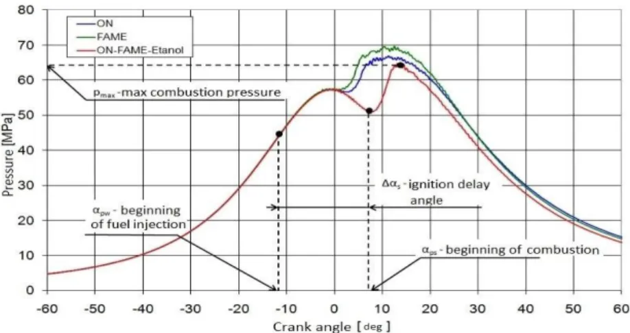
On the basis of the pressure recorded in the combustion chamber as a function of the crank angle for each point of motor operation parameters such as the maximum combustion pressure, the efficiency, the hourly fuel consumption, the specific fuel consumption, hourly air consumption, self-ignition delay angle were determined and
1 Dr hab. Inż. Piotr Orliński, Institute of Vehicles, Warsaw University of Technology 2 Mgr Inż. Paweł Kruczyński, BU Power Systems Polska Sp. z o.o.
calculated. The principle of setting auto-ignition delay angles, as well as the maximum combustion pressure directly from the indicator diagram is shown in Figure 1.
Fig. 1.Methodology for determining the basic parameters of the combustion process from indicator diagram; n = 2200 rev/min
Waveforms obtained from the measurement of pressure in the combustion chamber have been used to analyze the mathematical process of heat release in the combustion chamber. Each engine operating point was analyzed using a numerical algorithm created in MathCad program. Parameters such as heat release rate, the relative degree of burnout dose, burn of 95% dose, the kinetic and diffusion phases share in the combustion process were determined, which the principle of setting is shown in Figure 2.
Fig. 2.Methodology for determining 95% dose burn duration and kinetic (28%) and diffusion (72%) phases share during combustion
The pressure in the cylinder changes with the angle of rotation of the crankshaft by a change in volume, the burning process, the heat transfer to the cylinder walls and other parameters. The first two factors have the greatest impact on the change in pressure. Influence of volume change in the cylinder on pressure is obvious, while the data of burning process can be obtained by measuring pressure or computer simulation. Thus obtained cylinder pressure as a function of the volume in the combustion chamber provides valuable information necessary for the further analysis of the burning process. On the basis of the obtained data pressure as a function of volume in both the linear and logarithmic scale can be plotted - Figure 3 and 4.
Fig. 3-4. Combustion pressure as a function of cylinder volume in both the linear and logarithmic scale
On the graph in logarithmic scale compression stroke corresponds to a straight line - AB. Start of burning process is a place where the straight line crosses the arch - the point B. The end of the burning process is localized at the point C, where a straight line corresponds to the expansion stroke becomes approximately parallel to the straight line corresponding to compression stroke. This behavior is caused by the fact that both compression of unburnt blend from the previous cycle, and the expansion of the burnt gases are close to the adiabatic, isentropic transition which shall be:
(1) Graph of the combustion pressure as a function of a volume approximately allows you to specify the beginning and end of burning process, but does not provide any information on the mass of combustion. Technique for estimating the mass of combustion was developed by Rassweiler and Withrow. They correlated the data from the pressure in the combustion chamber with pictures of flame, and showed how the above equation can be used to determine the effect of the volume on pressure during combustion. Assuming that the unburned gas filling volume Vu against flame at any
angle of rotation of the crankshaft during combustion is compressed polytropically by advancing flame front, the volume Vu0 when the ignition starts:
Similarly, burnt gas behind the flame filling volume Vb will fill at the end of burning
process the volume of Vbf, which takes the value:
(3)
Mass combustion xb is equal 1-(Vu0/V0) and Vbf/Vf, where V0 and Vf are respectively
the volumes of the cylinder at the time of ignition and at the end of burning process. Knowing that V=Vu+Vb and taking into account the previous equations:
(4)
This equation was used in the calculation algorithm to determine the relative degree of burn dose and then to burn dose rate, which is derived from this value. Heat release rate is the product of burn dose rate and mass fuel consumption per one cycle.
3. Simulation results
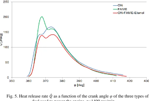
Figure 5 presents the heat release rate of three types of fuel used to power the engine for engine speed n=1400 rev/min which is the speed when engine has the maximum torque. Figure from 6 to 8 presents the heat release rate for each type of fuel used to power the engine depending on the engine load. Figure 9 presents the relative degree of burn dose of three types of fuel used for maximum torque engine speed. Figure from 10 to 12 presents the relative degree of burn dose for each type of fuel used to power the engine depending on the engine load. Figures from 13 to 15 presents kinetic and diffusion phases share during the combustion for each type of fuel used – engine was running at maximum torque speed. Figure 16 presents comparison of 95% dose burn duration of the three types of fuel used to power the engine.
Fig. 5. Heat release rate as a function of the crank angle φ of the three types of fuel used to power the engine, n=1400 rev/min
Fig. 6. Heat release rate as a function of the crank angle φ for the engine powered with diesel fuel depending on the engine load, n=1400 rev/min
Fig. 7. Heat release rate as a function of the crank angle φ for the engine powered with FAME depending on the engine load, n=1400 rev/min
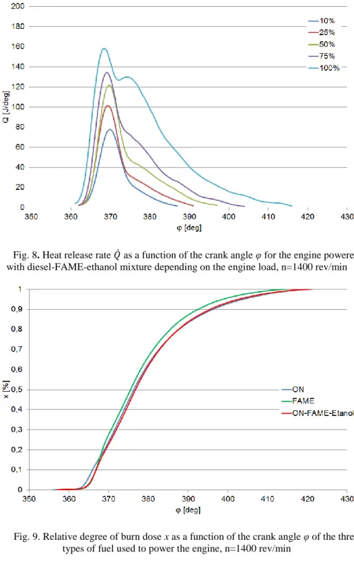
Fig. 8. Heat release rate as a function of the crank angle φ for the engine powered with diesel-FAME-ethanol mixture depending on the engine load, n=1400 rev/min
Fig. 9. Relative degree of burn dose x as a function of the crank angle φ of the three types of fuel used to power the engine, n=1400 rev/min
Fig. 10. Relative degree of burn dose x as a function of the crank angle φ for the engine powered with diesel fuel depending on the engine load, n=1400 rev/min
Fig. 11. Relative degree of burn dose x as a function of the crank angle φ for the engine powered with FAME depending on the engine load, n=1400 rev/min
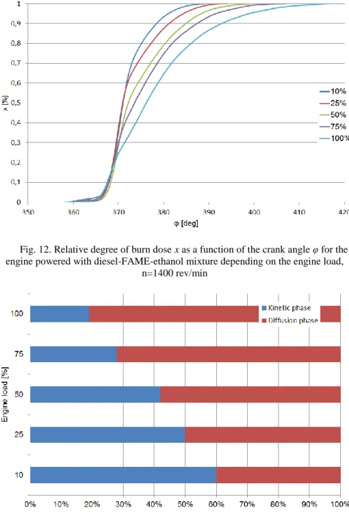
Fig. 12. Relative degree of burn dose x as a function of the crank angle φ for the engine powered with diesel-FAME-ethanol mixture depending on the engine load,
n=1400 rev/min
Fig. 13. Kinetic and diffusion phases share during combustion for the engine powered with diesel fuel depending on the engine load, n=1400 rev/min
Fig. 14. Kinetic and diffusion phases share during combustion for the engine powered with FAME depending on the engine load, n=1400 rev/min
Fig. 15. Kinetic and diffusion phases share during combustion for the engine powered with diesel-FAME-ethanol mixture depending on the engine load, n=1400
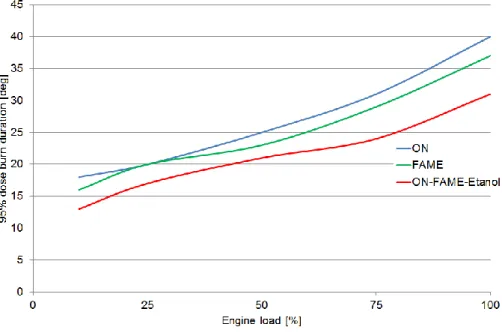
Fig. 16. Comparison of 95% dose burn duration of the three types of fuel used to power the engine, n=1400 rev/min
4. Conclusions
The results of research are significantly influenced by construction parameters of the object of analysis (eg. fuel injection pressure, the compression ratio), engine operating conditions, the methodology of experimental studies. Comparing the obtained results with the results described in other publications, in which biofuels and mixtures thereof with conventional diesel fuel and ethanol were also studied can be seen similar patterns.
On the basis of obtained results of PERKINS engine powered by three fuels can be concluded that for fuel FAME:
- engine supply causes a slight increase in the maximum combustion pressure in the cylinder in all engine operating points investigated,
- engine supply slightly shortens the period of 95% fuel dose burn,
- engine supply affects the larger share of the diffusion phase in the combustion and with increasing load this share is growing.
For a motor powered by a mixture of diesel-FAME-ethanol can be concluded that: - engine supply significantly reduces the maximum combustion pressure,
- engine supply significantly shortens the period of 95% fuel dose burn,
- engine supply significantly affects the greater part of the kinetic phase in the combustion process, but as the load increases this share is decreasing.
This can be explained by a much poorer properties mixture diesel-FAME-Ethanol, in particular, a lower limit of the cetane number and calorific value and a higher tendency to vaporize the fuel injection into the combustion chamber.
As shown by the study and performed calculations and the use of a mixture of fuel FAME and diesel-FAME-ethanol leads to a significant modification of the combustion process. To effectively improve the performance and emissions of the fuels supplied
engine is required additional adjustment of the engine, in particular fuel injection angle adjustment.
References:
[1] Lakshminarayanan P.A., Aghav Y.V.: Modelling Diesel Combustion, Springer, 2010.
[2] Eberhardt J.: Fuels of the Future for Cars and Trucks, US DOE, 8th Diesel Emissions Reduction Conference (DEER), San Diego, CA, August 2002.
[3] Majewski W., Khair M.: Diesel emissions and their control, SAE International, 2006.
[4] Szlachta Z.: Zasilanie silników wysokoprężnych paliwami rzepakowymi, Wydawnictwo Komunikacji i Łączności, Warszawa 2002.
[5] Kwanchareon P. i in.: Solubility of a diesel-biodiesel-ethanol blend, its fuel properties and its emission characteristics from diesel engine. Fuel, 86, 2007, s. 1053-1061.
[6] Young M.B., Lienesch J.H.: An Engine Diagnostic Package (EDPAC) - Software for Analyzing Cylinder Pressure-Time Data. "SAE Paper" 1978, nr 780967 [7] Wimmer A., Glaser J.: Indykowanie silnika. Wydanie polskie, AVL List GmbH,
Przedstawicielstwo w Polsce, Warszawa 2004.
[8] Merkisz J.: Emisja Cząstek Stałych przez Silniki Spalinowe o Zapłonie Samoczynnym, Poznań 1997.
[9] Heywood, J.B., Internal Combustion Engine Fundamentals, McGraw-Hill, 1988 [10] Rychter T., Teodorczyk A.: Modelowanie matematyczne roboczego cyklu silnika
tłokowego, Państwowe Wydawnictwo Naukowe, Warszawa, 1990.
[11] Ambrozik A., Ambrozik T., Łagowski P. The influence of hydrocarbon fuels and biofuels on self-ignition delay period. Teka Komisji Motoryzacji i Energetyki Rolnictwa 2007(7), s. 15-23.
[12] Kruczyński S.: Performance and emission of CI engine fuelled with camelina sativa oil, Energy Conversion and Management 2013(65), s. 1–6. [13] Zabłocki M.: Wtrysk i Spalanie Paliwa w Silnikach Wysokoprężnych,
Wydawnictwa Komunikacji i Łączności, Warszawa, 1976.
[14] Kowalewicz A.: Podstawy procesów spalania, Wydawnictwa Naukowo-Techniczne, Warszawa, 2000.
[15] Mollenhauer K., Tschoeke H.: Handbook of Diesel Engines, Springer, 2010. [16] Kowalewicz A.: Systemy spalania szybkoobrotowych tłokowych silników
spalinowych, Wydawnictwa Komunikacji i Łączności, Warszawa, 1990.
[17] Rychter T, Teodorczyk A.: Teoria silników tłokowych, Wydawnictwo Komunikacji i Łączności, Warszawa 2006.
Abstract
In this study the performance and emissions as well as combustion process of diesel engine fuelled by chosen fuels, including biofuels was analyzed. The intermediate engine parameters which were obtained in the process of mathematical modeling, using an algorithm developed in MathCAD were investigated. Heat release rate in the cylinder, the relative degree of burn-dose, the duration of burning 95% dose, and estimated percentage of the kinetic and diffusion phases during the combustion process. The engine used three fuels: fatty acid methyl ester of rapeseed oil - FAME, a mixture of oil,
FAME and ethanol - ON-FAME-Ethanol (in which each component was the third volume) and diesel hydrocarbon fuel.
Keywords: biofuels, combustion process, heat release
METODA SYMULACYJNA USTALANIA PARAMETRÓW PROCESU SPALANIA PALIWA W SILNIKU O ZAPŁONIE SAMOCZYNNYM Streszczenie
W artykule poddano analizie proces spalania oraz osiągi i emisję toksycznych składników spalin silnika o zapłonie samoczynnym zasilanego wybranymi paliwami w tym biopaliwami. Przebadano pośrednie parametry procesu spalania uzyskane w procesie modelowania matematycznego przy użyciu algorytmu stworzonego w programie MathCAD. Zbadano przebieg wydzielania ciepła w cylindrze, względny stopień wypalenia dawki, czas wypalenia 95% ładunku oraz oszacowano procentowy udział faz kinetycznej i dyfuzyjnej podczas procesu spalania. Silnik zasilany był trzema paliwami: FAME, mieszaniną ON-FAME-etanol (w której każdy ze składników stanowił jedną trzecią objętości) i olejem napędowym pochodzenia węglowodorowego.