IMPLEMENTATION OF THE ADAPTIVE FILTER
FOR VOICE COMMUNICATIONS
WITH CONTROL SYSTEMS
Abstract:
In the paper is described use of the draft method for optimal setting values of the filter length M and of the step size factor μ of the adaptive filter with LMS algorithm in the application of the suppression of additive noise from the speech signal. In the application of voice communications with control systems for operational technical functions controlling in buildings was implemented the adaptive filter with LMS (Least mean square) algorithm on the signal processor DSK TMS320C6713.
Keywords:
Adaptive filter, additive noise, speech signal
INTRODUCTION
This paper describes a proposition of the method for optimal adjustment parameters of the adaptive filter with LMS algorithm in the practical application of suppression of additive noise in a speech signal for voice communication with control system NIKOBUS. System NIKOBUS is used for operational technical functions controlling in buildings. Adaptive filter with LMS algorithm is implemented in the signal processor DSK TMS320C6713 (DSK - Digital Signal Processor Starter Kit). For optimum settings of the step size parameter of the adaptive filter with the LMS (Least Mean Square) algorithm is necessary ensuring the stability and convergence of the LMS algorithm. Optimum value of the length M of the adaptive filter is settings through the use
of the DTW criterion (DTW–Dynamic Time Warping). As a result of appropriate setting of the adaptive filter parameters is correct speech signal processing and subsequent correct the isolate words recognition through the use of software MY VOICE with software PROMOTIC in voice communication with control system NIKOBUS. PROMOTIC is a complex SCADA object software tool for monitor, control and display operational technical functions in building by the help control system NIKOBUS.
T
HEA
DAPTIVEF
ILTERW
ITHLMS
A
LGORITHMThe LMS algorithm is a linear adaptive filtering algorithm, which, in general, consists of two basic processes (Fig.1):
a) a filteringprocess, which involves
computing the output y(n) of linear filter in response to an input signal x(n) (1),
generating an estimation error e(n) by comparing this output y(n) with desired response d(n) (2),
b) an adaptive process(3), which involves the automatic adjustment of the parameters w(n+1) of the filter in accordance with the estimation error e(n).
( ) ( )
n n n y w x T = ) ( , (1)( ) ( )
n yn d n e( )= − (2)( ) ( )
n wn x(
n w +1= +2μ
e(n))
(3)w(n) is M tap – weight vector
w(n+1) is M tap – weight vector update [1], [2], [3].
Fig.1. FIR LMS adaptive filter realization [2] CALCULATING OF STEP SIZE PARAMETERμ
Determination of step size parameter μ is important for conduct of the LMS algorithm. When selecting parameter μ terms of a compromise between the two aspects. Large values μ can lead quickly to the optimal settings of the LMS algorithm for speech signal processing. On the other hand, increase of the value μ can make a mistake of the speech signal processing in further steps. Small value μ ensure stability and convergence of the LMS algorithm. As a result small value μ is possible slow down in the convergence of the LMS algorithm and, consequently, increasing the inaccuracies in the filtration non-stationary signals [1].
For computing of the optimal value of the parameter μ is possible use following equation
(
1 M)
.tr[R] M + = μ (4) M- parameter misadjustment,μ − step size parameter,
tr[R] - trace of R, which mean sum of the diagonal elements of R.
R - autocorelation matrix from input signal
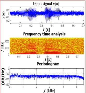
Fig.2. Waveform [5], spectrogram (frequency time analysis) and periodogram of power spectral density
estimate [7] of desired speech signal d(n) of isolated word "jeden" to the input of adaptive filter with LMS algorithm implemented on the DSK TMS 320C6713
USE DTW CRITERION FOR DETERMINATION OF
THE LENGTH M
The correct determination of the length M of the adaptive filter is very important. When the length M of the adaptive filter is low, the speech signal processing as a result of a small number of parameters of the adaptive filter is inaccurate. High value of the adaptive filter length M lead to inaccurate speech signal processing by influence of the estimator variance increase.
In this work was used DTW criterion for determining value of length M of adaptive filter. Value of the adaptive filter length M is determined by set values of the length M in interval {0 to 150} and calculating of the minimum distance (similarity) between the
reference vector R=[r(1), . . . , r(R)] of the length R (desired signal d(n) (Fig.2)) and the test sequence O=[o(1), . . . , o(T)] of the length T (output signal e(n) from adaptive filter). Words are almost never represented by the sequence of the same length R T. The distance d between the sequences O and R is given as minimum distance over the set of all possible paths (all possible lengths, all possible courses) [4], [7], [9], [10].
≠
Fig.3. Waveform [5], spectrogram (frequency time analysis) and periodogram of power spectral density
estimate [7] of speech signal x(n) of isolated word "jeden" with additive noise to the input of adaptive filter with LMS algorithm, implemented on the DSK
TMS 320C6713. Minimum distance computation
{ } ( , ) min ) , (O R C DC O R D = (5)
is simple, when normalization factor Nc is no
function of path and is possible write Nc=N for
c ∀ { } [ ( ( )) (, ( )) ( ) min 1 ) , ( 1 k W k r k t d N D Kc c k c c C
∑
= = o r R O ] (6)For example are given below (Tab.1) calculated values of distance d between Czech isolated words "jeden" and other isolated words "dva", "tři", "čtyři" by using DTW criterion.
Tab. 1 Calculated values of distance d jeden–
jeden jeden– dva jeden– tři jeden– čtyři
d=0 d=0,713 d=1,218 d=1,415
Based on the calculated values of distance d between the isolated Czech words (Tab.1) is a cap for recognized isolated word determined on the value of d<0,2. If the value of the distance d will greater than d>0,2, compared isolated words are not recognized.
DRAFT METHOD
Draft method was applied in next steps [10]: 1.Calculation of the step size parameter optimal value μ (4) for desired signal d(n) and input signal x(n) with additive noise (with SSNR (Segmental Signal to Noise) and with parameter misadjustment M) to adaptive filter with LMS algorithm.
2.Values of the adaptive filter length M are set in interval {1 to 150}.
3. For reference vector R is used desired signal d(n) (Fig.2) to the input of DSK TMS320C6713 (adaptive filter with LMS algorithm is implemented on the DSK TMS320C6713) .
4. As a test signal to calculate the distance d (5), (6) between the signals being compared, was used output error signal e(n) (Fig.5), (distance d calculated values are in Tab.2).
As the optimal value of M order adaptive filter with LMS algorithm was chosen value of the filter order M for a minimum distance d of two compared signals (Fig.7) d(n) and e(n) (Fig.5) for corresponding adaptive filter length M, (Tab. 2).
Tab. 2 Calculated values of distance d, length M and parameter μ the set parameter misadjustment M. Misadjustment M M=10% M=20% M=30% calculated value of μ μ1=0,1025 μ2=0,1879 μ3=0,2602 calculated value of M M=21, M=40, M=99, calculated value of d d=0,1835 d=0,2645 d=0,3073 EXPERIMENTAL PART
The proposed method for determining of the order M adaptive filters with LMS algorithm was used in the implementation of LMS adaptive filter algorithm in an application to suppress
noise n(n) from the speech signal out of the DSK TMS320C67113 (Fig. 4).
Fig.4 Implementation of two channel structure of adaptive filter with LMS algorithm in an application
for the suppression of additive noise on the DSK TMS320C6713 [6].
Fig.5. Waveform [5], spectrogram (frequency time analysis) and periodogram of power spectral density
estimate [7] of output error signal e(n) from the adaptive filter with LMS algorithm implemented on
the DSK TMS320C6713.
Input signal x(n) (Fig.3) is composed of the desired signal d(n) (Fig.2) + additive noise n(n). The segmental signal to noise ratio of input signal x(n) is SSNR=6,6756(dB). Input signal x(n)
is generated to the input of DSK TMS320C6713. The block diagram with implementation of the adaptive filter for voice communications with control system NIKOBUS is in Figure 7. In the Table 2 are calculated values d between output signal e(n) from adaptive filter with LMS algorithm and desired signal d(n) for the values parameters set of adaptive filter order M and step size parameter μ.
The calculated values of distance d (Tab.2) in MATLAB shows, that an isolated word "jeden" (Fig.5) from adaptive filter output was recognized (d<0.2), when optimal set parameters of adaptive filter with LMS algorithm are M=21, μ1=0,1025 and M=10%.
Fig.6. Calculated values M=21 and d=0,1835 of the adaptive filter with the LMS algorithm (μ=0,1025, SSNR=6,6756(dB), M=10%) by using DTW criterion.
Fig.7 Implementation of the adaptive filter for voice communications with control system NIKOBUS [8]. Empirically was found, that the parameter
μ
for the implementation of adaptive filter with LMS algorithm implemented on the DSK TMS320C6713 allow set only in the rangeμ
=1.10−8toμ
=1.10−12. The adaptive filter length M can be set only in the range M=16 to M=52.Optimal settings of parameters M=21 and
μ
=1.10−8of adaptive filter with LMS algorithmin the application of noise suppression implemented on the DSK TMS320C6713 allow recognition of isolated word "jeden" through the software MY VOICE.
CONCLUSION
In this paper was described the way of verification of the proposed method on the structure of adaptive filter with LMS algorithm in application of suppressing noise from speech signal by simulations in MATLAB software.
The proposed method was verified by the practical realization of the structure of adaptive filter with LMS algorithm in the application for suppressing additive noise in speech signal by implementation on the DSK TMS320C6713. This implementation is used in voice communication with bus system NIKOBUS, which is used for controlling of operating-technical functions in buildings. For speech recognition in voice communication has been used software MY VOICE (Fig.7) with software PROMOTIC.
ACKNOWLEDGMENT
The paper could be published with the financial contribution from the Internal Grant Agency VŠB TU Ostrava in the grant entitled Diagnostics mechatronic systems, filed in 2009
REFERENCES
[1.] FARHANG – BOROUNJENY, B.: Adaptive Filters, Theory and applications, John Wiley & Sons, Chichester, 2005,
[2.] POULARIKAS, D. A. - RAMADAN, M. Z.: Adaptive filtering primer with MATLAB, Taylor & Francis Group, 2006
[3.] HAYKIN S.: Adaptive filter theory, PRENTICE HALL, New Jersey 2002, ISBN 0-13-090126-1
[4.] UHLÍŘ J., SOVKA P., POLLÁK P., HANŽL V., ČMEJLA R.: Technologie hlasových komunikací, nakladatelství ČVUT Praha 2007, ISBN 978–80–01–03888–8
[5.] PSUTKA J., MULLER L.; MATOUŠEK J., RADOVÁ V.: Mluvíme s počítačem česky, ACADEMIA Praha 2006, ISBN 80–200-1309-1
[6.] CHASSAING R., REAY D.: Digital Signal Processing and Applications with the TMS320C6713 and TMS320C6416 DSK, John Wiley & Sons, Inc. New Jersey 2008, ISBN 978–0-470-13866-3
[7.] UHLÍŘ J., SOVKA P.: Číslicové zpracování signálů, Vydavatelství ČVUT, Praha 1995, ISBN 80–01–01303–0
[8.] SMÉKAL Z., SYSEL P.: Signálové procesory, nakladatelství Sdělovací technika, Praha 2006, ISBN 80–86645–08–8
[9.] ČERNOCKÝ J.: Zpracování řečových
signálů – studijní opora,
http://www.fit.vutbr.cz/.cernocky, VUT Brno, 2006
[10.] VAŇUŠ J.: Hlasová komunikace s řídícím systémem, Disertační práce, VŠB TU Ostrava, 2009
AUTHORS &AFFILIATION
1.
J
ANVA
ŇUŠ
1.DEPARTMENT OF GENERAL ELECTRICAL
ENGINEERING,FEECS,VSB-TECHNICAL UNIVERSITY
ACTA TECHNICA CORVINIENSIS – BULLETIN of ENGINEERING
copyright © UNIVERSITY POLITEHNICA TIMISOARA
FACULTY OF ENGINEERING HUNEDOARA
5, REVOLUTIEI 331128–HUNEDOARA ROMANIA http://acta.fih.upt.ro Scientific supplement of ANNALS of FACULTY ENGINEERING HUNEDOARA – INTERNATIONAL JOURNAL of ENGINEERING ISSN: 1584-2665 [print] ISSN: 1584-2673 [CD-Rom] copyright © UNIVERSITY POLITEHNICA TIMISOARA
FACULTY OF ENGINEERING HUNEDOARA
5,REVOLUTIEI
331128–HUNEDOARA
ROMANIA