A Systems Theoretic Approach to the
Security Threats in Cyber Physical Systems:
Applied to Stuxnet
Arash Nourian
Stuart Madnick
Working Paper CISL# 2015-07
December 2015
Cybersecurity Interdisciplinary Systems Laboratory (CISL)
Sloan School of Management, Room E62-422
Massachusetts Institute of Technology
Cambridge, MA 02142
A Systems Theoretic Approach to the
Security Threats in Cyber Physical Systems
Applied to Stuxnet
Arash Nourian and Stuart Madnick,
Member, IEEE
Abstract
Cyber Physical Systems (CPSs) are increasingly being adopted in a wide range of industries such as smart power grids. Even though the rapid proliferation of CPSs brings huge benefits to our society, it also provides potential attackers with many new opportunities to affect the physical world such as disrupting the services controlled by CPSs. Stuxnet is an example of such an attack that was designed to interrupt the Iranian nuclear program. In this paper, we show how the vulnerabilities exploited by Stuxnet could have been addressed at the design level. We utilize a system theoretic approach, based on prior research on system safety, that takes both physical and cyber components into account to analyze the threats exploited by Stuxnet. We conclude that such an approach is capable of identifying cyber threats towards CPSs at the design level and provide practical recommendations that CPS designers can utilize to design a more secure CPS.
Index Terms
CPS security design, Stuxnet analysis, CPS, STAMP, Security and safety analysis.
1. INTRODUCTION
T
HE increased challenges of today’s life such as energy scarcity, require the integration of computing intelligence into physical world. Cyber physical systems (CPS) [1] such as industrial control systems are examples of such integration where the effects on physical world are controlled through the use of smart technologies created by computers [2].With physical manifestations in the real world, attacks on CPSs can cause disruption to physical services or create a national disaster. As a cyber physical system requires a tight coupling between the physical and cyber controlling components, it is crucial to ensure that the system is not only safe but also secure for all the cyber and physical processes. Therefore, protecting the CPSs’ against cyber attacks is of paramount importance.
Traditional IT security methods can be applied to protect a CPS, such as a critical infrastructure system, against cyber threats or threats imposed by malicious insiders. However, due to the unique characteristics of a CPS, traditional IT security strategies and approaches are not sufficient enough to address the security challenges of a CPS [3] [4] [5] [6] [7] [8]. For example, installing security patches or numerous system updates that require taking the system offline is difficult, not economically justifiable, and often not feasible. Also, new updates or security patches may create other problems such as in a case where a nuclear power plant accidentally was shutdown after a software update [9]. Recently, it has been shown that attackers can take control of air planes by having access to Wi-Fi services provided by the planes [10].
A. Nourian and S. Madnick are with the Massachusetts Institute of Technology (MIT), Cambridge, MA, USA. E-mails: nourian@mit.edu, smadnick@mit.edu
Most of the efforts for protecting CPSs or even standards such as NIST 800-53 have focused on applying traditional IT security mechanisms to threats such as those enumerated above. Although these efforts can provide guidance and recommendations in improving the security of a CPS, they are not enough. There is a lack of a framework for assessing the security in designing a CPS or evaluating the level of the security guarantee in a functional CPS at the design level.
In this paper, we utilize a system theoretic framework to evaluate and enhance the security of CPSs. The framework can be used in CPS attack modeling and threat assessment as well as diagnosis methods for stealthy attacks against a CPS. We evaluate the effectiveness of our proposed framework in terms of finding vulnerabilities and protecting a CPS by applying it to the Stuxnet case.
The rest of the paper is organized as follows. Section 2 provides background on CPSs. Section 3 discusses the traditional approaches for evaluating safety and security in CPSs. In section 4, we review how Stuxnet works and infects the CPSs. Section 5 contains a thorough application of proposed security analysis scheme on Stuxnet. Section 6 summarizes the results of our analysis.
2. CYBERPHYSICALSYSTEMS
A cyber physical system (CPS) is a system that provides the control of physical components through cyber-based commands. It is a physical system whose operations are integrated, monitored, and/or controlled by a computational core [1]. By integrating actuators, control processing units, sensors, and communication cores, a CPS forms a control loop for each of the physical component of the system.
The main components of a CPS are SCADA (supervisory control and data acquisition), DCS (distributed control system), and PLC (program logic controller) [11]. The main role of SCADA is to gather and control geographically dispersed assets ranging from controlling sensors within a plant to controlling power dissemination in a country. SCADAs are widely used in various critical infrastructures such as electrical power grids, water distribution systems, and oil refineries. DCS on the other hand, controls the controllers that are grouped together to carry out a specific task within the same geographically location. Both SCADA and DCS use PLC devices to control the industrial components and processes. PLCs are typically programmed from a Windows-based machine by an operator. The operator uses SCADA and DCS for various controlling tasks such as process monitoring and configuring control parameters.
Due to the critical nature of a CPS, strong security and privacy mechanisms are needed to restrict unauthorized access to the critical components of a CPS. Traditionally, industrial control systems were considered secured as long as they are air-gapped, not connected to outside world. This notion is not valid anymore as more and more industrial control systems are connecting to outside of their perimeter for various reasons such as providing better services similar to smart grids or updating their softwares. Futhermore, having a direct connection to outside world is not necessary to make a CPS vulnerable to cyber attacks. Cases like Stuxnet has shown that even without direct connections to outside cyber world, cyber physical systems are still vulnerable.
Most approaches for increasing the level of security within a CPS look at securing the individual components of the CPS (i.e. security at component level) such as sensors, PLCs, actuators, or communication protocols [12]. These approaches consider each component inside a CPS in isolation and follow the standard practices to make the component secure against security threats such as input validation or firmware tampering.
Although the security of individual components is important, it is not enough. A CPS can be attacked by compromising the interaction between components without hacking the individual components within a CPS [13]. By creating changes in the interaction of components, attackers create different outputs than what was requested by the operators. For example, an attacker can cause delays in transferring the information
from sensors to SCADA, triggering unwanted actions imposed by the delay in receiving the requested results by SCADA. Attackers can also create nuisance alarms to desensitize operators to react to a real CPS problem in the long run. Then, they launch their actual malicious command after the nuisance alarm attack.
One of the key advantages of cyber physical systems is networking the different components of the systems for providing better and efficient services. In a network environment where all nodes are considered trusted, every component of the system (inside or outside) can be a potential entry point for attackers. Thus, the entry points for attackers are increased as the sizes of CPS network increases. In addition, due to employing different devices from different vendors, it is difficult to create a unified security enforcement mechanism. Often securing the servers and SCADAs overshadows the security of other low level important components and attackers take the advantage of that. Therefore, identifying all critical control points and the component interactions that affect those points are of paramount importance to enhance the security of a CPS. As CPSs get more complex, a system-theoretic approach that considers system complexity can help to properly address the security of a complex CPS at the design level. Such an approach should be able to identify the vulnerable points, subsystem interactions and their effects on vulnerable points and provide recommendations on how to increase the security of a CPS.
3. RELATEDTECHNIQUES FORSAFETY ANDSECURITYANALYSIS INCPS
Traditionally, several approaches are available for safety analysis in CPS [14]. Among the most popular ones are Fault Tree Analysis (FTA) [15], Failure Mode and Effects Analysis (FMEA) [16], Hazard Analysis and Critical Control Points (HACCP), and Hazard and Operability Study (HAZOP) [16].
Most of the traditional approaches are based on risk assessment and risk analysis of a system and can be defined as a set of systematic methods for performing the following
• Identifying hazards-a situation with the potential for creating damage
– Hazards related to actions: undesirable system actions are taken or desirable system actions are not taken
– Hazards related to timing: A desirable system actions is performed too soon or too late
– Hazards related to sequence: A desired action in a sequence of actions is skipped or the actions in a sequence are performed out of order
– Hazards related to amounts: A desired action is performed too much or too little. • Quantifying risks-the likelihood of a specific effect within a specified period • Determining components safety measures
However, none of these traditional techniques are geared towards addressing the threats that compromise the interactions among components in a CPS because these approaches consider individual components or subsystems in isolation in addressing the safety of a CPS. In addition, since these approaches are mainly designed for safety analysis, they can not be used effectively to address the security concerns in a CPS as safety and security are different in nature. A system may be safe but not secure. For example. a system can allow unauthorized modifications of the control parameters within the safe range without being detected by system safety controllers, creating undesirable output that was not requested by the operator. In this section we overview the above mentioned approaches and discuss their limitations in addressing the security issues in a CPS.
A. Failure Mode and Effects Analysis (FMEA)
FMEA is performed to identify individual failure modes of a system or its components and how they can affect the system reliability in general. Failure modes are situations or conditions that cause a failure to occur.
However, failure effects are consequences a particular failure mode can have on the system functionality [16]. For example, if a component fails, what would be its effect on the overall system functionality.
FEMA is usually performed at the start of the development phase once the design phase is completed. Therefore, the result of FEMA can be used for product development and improve the process. FEMA uses Risk Priority Number (RPN) as part of its quantitative analysis to identify the reliability rates for each failure mode. RPN shows the risk of identified hazard based on severity and probability. RPN is calculated as follows [16]:
RP N =Severity×
P robability of Occurrence×Detection Ranking
Researchers have investigated the benefits of performing FMEA to find the failure modes of software that are complex to detect [17] [18] [19] . Such approaches can be used in the software design step to verify and validate the software behaviors in isolation. However, they do not support the failure modes caused by the interactions of software components in complex mission critical systems.
The result of FEMA provides all failure modes, their effects on the system, and quantitative predictions on system hazards. However, a system can fail while all individual components performing their normal operations such as the Mars Polar incident [14]. While FEMA provides analysis for a single point of failure, it fails to consider multiple combinations of failures as it assumes that the system fails only if a component fails.
B. Limitations of Traditional Approaches
Although traditional approaches can aid in addressing the safety of a complex systems, they fail to consider the numerous interactions among different components, heterogeneity of the networks, and cyber connections. Traditional methodologies use the decomposition approach on safety and consider safety as a reliability issue. One of the issue of this approach is that it assumes any failure is the result of a linear chain of undesired events that are caused from a single random component failure. However, most of security threats in CPS happens when the system is compromised without any evident failure [14]. For example, due to lack of authentication for control parameter modifications, an attacker is able to modify the control parameters within the safe range. In this case, no failure happens but the system’s security is compromised. Therefore, traditional approaches are often not able to address the security of complex systems.
Similarly, in the software security domain, methods such as Microsofts STRIDE/DREAD [20] or attack tree [21] exist for threat and vulnerability analysis. While such software security analysis methods are mature, their application to analysis of the security/safety-related incidents in CPS fails to consider the interactions among different components as well as that of the control loops.
Recently, a new system based approach, Systems Theoretic Accident Model and Process (STAMP) [14] is introduced that does not consider safety a reliability issue and designed to address the need for an effective approach for addressing safety in complex systems, such as a CPS, by considering interactions among components in designing safe systems. In this paper, we show that STAMP can be adapted to be used as an effective approach to address security as well as safety in a CPS.
C. System Theoretical Accident Model and Process (STAMP)
The System Theoretical Accident Model and Process (STAMP) is a system based approach to safety and security. Figure 1 shows the STAMP model modules. The fundamental differences between STAMP
and other traditional approaches is that STAMP looks at systems as dynamic systems rather than static and consider safety and security of a system as a control problem not a reliability issue.
Figure 1: Modules of STAMP model [22]
According to STAMP, the individual components inside a system require control by enforcing sets of constraints. STAMP assumes that the inadequate enforcement of the required constraints in all levels including design and development can lead to a failure or an accident. In STAMP, any undesired events that lead to system failure without component failure or miss interactions among components are called accident. STAMP analyzes the hierarchical control structure by monitoring how the contextual control structures (i.e. all control structures in different system levels) interact to have a safe and secure state. STAMP analysis helps in finding the mitigations of the detected unsafe state, control loops, and their interactions, which were not possible in the traditional approaches.
Having a holistic system thinking approach and considering interaction among components, STAMP also not only allows the analysis of failures and unsafe states but also can be used to uncover states that are related to organizational, cyber, and environmental failures. STAMP methodology is based on the following
Figure 2: Simple Control loop [14] pillars [14]:
• Safety Constraint • Process Model
The safety control structure shows the hierarchy of all control loops in the system from higher levels to lower levels [14]. Figure 2 shows a standard control loop. As shown in Figure 2, four components-Controller, Actuators, Controlled Process, and Sensors- are the building blocks of a simple control loop. As soon as the controller receives a command from the operator or other controllers, it runs the control algorithm associated for the received commands. The result of this step generates a command signal that tells the actuator to change the state of the controlled process. Then, the actuator informs the controlled process that the requested command is executed by sending the related controlled variables. Finally, the sensors verify the system state using the measurement variables and sends the result back to the controller. At this point, the controller compare the system state with the desired state and determines the subsequent actions. The process model that is run by the controller confirms the controlled process results.
Safety constraints are used to identify the safe and unsafe state of a system. They are derived from hazards that are defined in the system specifications. The successful design and enforcement of safety constraint increases system safety. In STAMP, these constraints are used to generate the system requirements that are mandatory to maintain the system safety. STAMP analysis not only shows where insufficient control action were in place but also shows which safety constraints were violated that brought the system to an unsafe state.
Using safety approaches to address cyber security concerns had been explored previously [23] [24] [25] [26]. In [27], the authors briefly claim that the STAMP methodology can be used both after an event to prevent future such events and before any such event to anticipate threats and mitigate them. To the best of our knowledge, this paper is the first STAMP-inspired detailed analysis of a major cyber physical system attack, Stuxnet. Though this was primarily a post event analysis, we also identify a threat, T5, that was not exploited by Stuxnet, as discussed later.
Causal Analysis based on STAMP (CAST) [14] is an application of STAMP for accident analysis that we utilize in this paper for the analysis of Stuxnet to show how STAMP can be used to address security risks of a CPS at the design level.
The core building of CAST is to investigate the control structure dynamics for accident analysis [14]. This investigation begins by looking at safety constraints and shows how the violation of a constraint related to system security can lead to a system failure by providing its hierarchical cascading effects on the overall system control structure.
The procedure for applying the CAST methodologies consists of 8 steps: 1) defining the system hazards, 2) finding safety constraints and safety requirements of the system, 3) defining the system control structure, 4) finding the possible events causing the failure or accident, 5) navigating through the system control structure and finding the insufficient control on each level and how they can cause failure and unsafe states, 6) analyzing all interactions and finding the potential factors affecting interactions that can lead to failure, 7) finding external (i.e. interactions with outside the boundary of a system) and dynamic factors that can affect the overall safety structure at any time, and 8) producing recommendations and possible modifications on the system design.
Although traditional methods such as FMEA and FTA share some properties with STAMP, the way STAMP analyzes safety is different with that of traditional methodologies. STAMP uses control problem analysis rather than reliability approach [14].
By showing what are the inadequate controls in the system control structure, CAST not only helps in the investigation of an accident but also reveals the real causes of the accident that can be useful in designing safe and secure systems. CAST has been applied to many industries such as aviation [28], railway [29],
medicine [30] and pharmaceuticals [31]. In Section 5, we apply CAST to one of the best known CPS malware, Stuxnet, and show how it can be used to identify the threats posed by Stuxnet. The results of the CAST analysis will be discussed in detail.
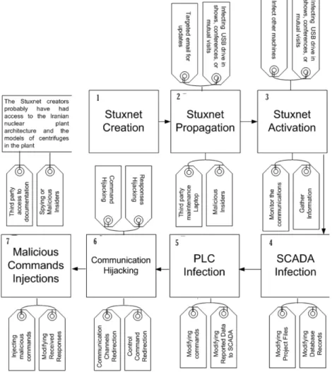
Figure 3: Stuxnet Attack Process (the numbers indicate the step-number in the attack process)
4. OVERVIEW OF THESTUXNETCASE
Stuxnet was first discovered by the VirusBlockAda company in June 2010 and infected computers all around the world. However, the majority of the computers were in Iran [32]. In the design of Stuxnet, several complex techniques have been used, making it one of the most complicated malwares targeting a CPS [33]. The process of infecting, activating, and launching the attack was carefully designed and probably had been tested on similar plant architecture for high degree of an effective impact since Stuxnet did not create any damage on other infected uranium enrichment facilities. Figure 3 shows the overall Stuxnet’s attack vector both before and after activation.
Inside a uranium enrichment infrastructure, PLCs are responsible for controlling centrifuges. As each PLC is configured uniquely, the configuration documentations are needed for any type of targeted attacks. In the case of Stuxnet, possible ways of accessing these documents can be either by the manufacturers, an insider, third party contractors or even snooping malwares that are designed specifically to gather information about an ICS in order to reverse engineer the actual architecture.
A. Stuxnet Infection Analysis
As the targeted uranium enrichment infrastructure was air-gapped (i.e. no cyber connections to outside world), propagation of Stuxnet was probably done whether through a USB drive or other infected external devices. Once the infected USB was connected to the maintenance laptop, Stuxnet was activated and infected all the network devices particularly printers, computers, database servers, and application servers. Stuxnet also infected major systems components ranging from SCADA to sensor readers as depicted in Figure 4. As shown in Figure 4, the original data flow from controllers to centrifuges was modified by the Stuxnet and these modification were not detected by safety measures in place.
Figure 4: Stuxnet Attack Digram
Stuxnet targeted Siemens S7/WinCC products that were commonly used in the Iranian uranium enrichment infrastructure. The PLCs in the S7 product were the target element exploited to launch the attack. To achieve this goal, Stuxnet utilized 3 zero-day vulnerabilities1 on Microsoft Windows operating systems to gain root access required for manipulation of PLCs [34] [35] [36]. The first exploited vulnerability was based on utilizing an old vulnerability that was used in the Conficker attack [34]. Stuxnet used the un-patched Conficker flaw in remote procedure call (RPC) to infect the potential hosts on the network. Stuxnet utilized the flaw to query the remote machines in the network to see whether Stuxnet is installed. If not, the infected machine sends Stuxnet to the uninfected machine.
The second was a flaw in handling of .LNK file that was used to launch the malicious code on the infected Windows machines [36]. .LNK files identify references to files. Traditionally, no test were done to verify the file even by anti-viruses. This vulnerability is utilized in Stuxnet to reference a file on infected drive that hold the virus. Once the virus is uploaded to the system and successfully infects the target machine, Stuxnet hides the .LNK file as well as the source file. For automatically launching the payload, “Autorun.inf” file is used to install the rootkit and loader as well as creating configuration and data files.
The third exploited vulnerability was a bug in the Print Spooler Service that was utilized to transfer the malicious code and then execute it on other machines in the network [35]. Utilizing this vulnerability, Stuxnet copies itself to accessible network shares such as administrative shares, and printer servers that are publicly available in the network. These vulnerabilities were patched by Microsoft after the detection of Stuxnet. However, this shows attackers knew the flaws better than the vendors since all the fix patches were created by the vendors after the Stuxnet was detected. It also shows patching the systems by the latest security patches by the vendor does not necessarily bring the required level of security since there can be serious vulnerabilities that are not yet detected by vendors. As operating systems are getting complex and developed modular by specialized teams, lack of communications among core module developer teams provides a ground for attackers to exploit vulnerabilities that arises from this flaw. Therefore, interaction among different modules should also be considered for security analysis in parallel with the security of individual module.
After the first load, Stuxnet performs the following tasks before launching any malicious activities against centrifuges known as probe-phase: 1) secretly recording normal operations for a full operation cycle, 2) playing the recording back to the controllers to maintain the appearance of a legitimate entity, 3) infecting other computers, and 4) maintaining the list of infected computers, monitor spread, and determine success in infecting attacked computers.
During the pre-attack phase Stuxnet utilizes various techniques to spread to other components in the system. For example, it infects any USB drives that is connected to the infected machines. It also infects the S7 project files-Siemens’s PLC project files. The infected project file subsequent openings on other machines infect them with the malware. Utilizing the WinCC database connections was another technique for spreading the malware. In this technique, the connection is used to infect the database. Once a database is infected, further connections to the database by other machines infected them.
In the complex structure of the uranium enrichment infrastructure, two components were the target of Stuxnet: functional components and software components. Functional components contain operating systems as the core modules running on a propriety hardwares. These systems do not allow any type of modifications on their modules by unauthorized users. Examples of functional components are automation systems such as DCSs (distributed control system), engineering systems such as PLCs, and communication channels. Software components are installed, configured, and updated by the systems’ user. Due to such characteristics, these components are the main targets by the attackers since attackers can steal the authorization of system users and modify software components on behalf of system users. The main software components that were targeted by Stuxnet were SCADA, web-servers(used to report some statistics to remote clients on the same network), sensors/Network adapters firmwares, CAS (central archive server), and database servers. Utilizing the information gathered during the probe-phase, Stuxnet replaced the legitimate modules of both functional and software components with illegitimate ones. Such modules were executing the commands designed by Stuxnet designers while reporting something else to the operators and informing them that their commands were successfully executed as shown in Figure 4. Readers are referred to [32] [37] [33] for more information on how Stuxnet works.
5. STUXNETCASTANALYSIS
Traditionally, bottom-up approaches are used to evaluate the safety of a system. However, as discussed in Section 3 some hazards and threats were not identified by standard practices and that caused the breakdown of most centrifuges. This shows why applying a linear traditional approach to a non-linear complex system2
was not enough. The security of a non-linear system is not solely directly proportional to the security of individual components. Therefore, a new approach that utilizes a system-thinking approach such as STAMP is required. The intent of our analysis is show whether the STAMP methodology, in particular to CAST, could have discovered the hazards that led to the centrifuges break down in the Stuxnet case. If those hazards were identifiable using STAMP, its recommended mitigations could have been applied in the design phase to prevent the same hazards to happen in new or current systems. Also, we show hazards identified by CAST that could not be found by traditional methodologies such as FMEA. Thus, our analysis confirms the advantage of applying a system model in security analysis that can improve the overall safety and security of complex systems.
In CAST each individual component of a complex CPS is analyzed in terms of safety to form a safety perception. Such analysis considers parameters such as incoming data, its source, and interactions with other components inside the operational system. The involved components in the analysis are then linked together to form larger sub-systems until a complete system is formed. However, the interactions between components as depicted in Figure 5 are usually not considered in other traditional approaches, making them insufficient to address the security needs of a CPS. Each link between two components in a loop is labeled with the first letter(s) of the originating component followed by the first letter(s) of the terminating component as shown in Figure 5.
Figure 5: Control loop
In the Stuxnet case the system (i.e. uranium enrichment infrastructure) is operated as follows. The operator may either issue a command to the centrifuges or other controlling components through SCADA or load a predefined operation configuration file that issues the previously defined operations sequences. Once the requested operation is performed within the desirable timeframe, the results are sent back to user for its verification. If the average turn-around time for the requested operation is delayed, then the system may go into a hazardous state.
The system allows the operator to either manually check the correctness of the results or use an automatic verification algorithm that runs a specific simulation for each operation. The algorithm compares the result of simulation with that of the received results for verification purposes. The operator is also able to monitor centrifuges status, PLC’s status, as well as other users activities.
After the operator or the automatic verification module verifies the correctness of the requested operation, the system automatically resets itself by performing the required readjustment process for the next new requested operation or the next operation in the sequence.
Traditionally, such a system undergoes serious risk analysis using traditional methodologies such FMEA to not only find the possible hazards caused by the specific system design but also implement the recommended
Figure 6: System Threats
mitigations derived from the analysis [38]. The case system probably had followed the same process as a standard practice recommended for all uranium enrichment infrastructure.
The user interacts with the system using the graphical user interface that records the user’s commands as well as showing the user the result of its requested operations. Figure 5 shows the typical operation loop in ICS. Lack of properly controlling such a loop as well as other system-wide loops were the main reasons that the Stuxnet attack went through as we show later in this section.
Figure 7: System security requirements and constraints
In the Stuxnet case, as described in the previous section, the interactions among operators, SCADA systems, PLCs, and sensors were intercepted and used to launch the malicious operations. As we later show by analyzing all the control loops within the system boundary, lack of authentication and result verification on feedback loops was also evident in the system architecture that made the system vulnerable to threats imposed by Stuxnet.
A. System threat identification
As discussed in Section 3, the first step in CAST is to define the system and hazards related to the accident. The system is the uranium enrichment infrastructure controlled by a set of automated tools such as SCADAs, PLCs, Sensors, and a communication network.
We define threats by extending the definition of hazards in STAMP as explained in Section 3 to consider states that are not hazardous but are undesirable by the users. For example, a centrifuge can spin within
the safe speed range but not with the speed requested by the operators. These states are caused mainly by attackers who circumvent the security measures to execute their control actions with parameters within the safe range. Using the definition of threats and the Stuxnet case analysis discussed in Section 5, most of the relevant threats within the studied system’s boundary are listed in Figure 6. These threats are identified based on our analysis of missing controls and the threats posed by Stuxnet. The description of each threats is as follows:
Figure 8: System components
1) The T1 threat of reporting fake results to the controllers is highly dangerous and can lead to issuing undesired operations from the controllers with a physical manifestation. As discussed in Section 5, the reported fake results to SCADAs led to not recognizing the actual damages to the centrifuges by the operators.
2) T2 is the threat where the system executes the requested operations by Stuxnet rather than that of the operators. Running centrifuges with the highest speed and switching their speed to the lowest speed without considering the speed requested by SCADA or the operator is an example such a threat. These threats are not recognized by the controllers in the system as such attacks hides the actual situation from the controllers, imposing another threat- T3.
3) T3 is the threat where malicious operations such those explained in T2 are concealed from the process view of controllers such as SCADAs. Since the design intent of the system was that always the correct results are available to the SCADAs, no proper controller verification step, such as a signal by a controller indicating whether the operation is performed correctly, was used in the original design to address such flaws.
4) T4 is the threat where the whole system was blind on the actual operations that were happening within centrifuges. Usually the actual results are reported by the centrifuge sensors to SCADAs. The original design intent did not consider result verification and reporting authentication to address this issue. 5) T5, the threat of delayed reporting, was not directly exploited by Stuxnet but the system was susceptible
to such a threat by Stuxnet as it was sitting as a middleware between controllers and physical devices, in this case centrifuges and were able to delay the reception of results by SCADAs. This may lead to launching undesired operations by SCADAs due to lack of results.
B. System Security Constraint and Security Requirements
The second step in the CAST analysis is to define the security constraints based on hierarchical control systems. Also, security requirements associated to each security constraints should also be defined to ensure that the security constraints are not violated. The security constraints and security requirements of Stuxnet case are shown in Figure 7
As it is shown in Figure 7, a security constraint is defined for each identified threat shown in Figure 6. For example, for T1, the defined security constraint indicates the receiving of the correct results by the controllers. As mentioned earlier, failure to enforce such constraint led to the T1 in the Stuxnet case. The security requirements that addresses this constraint is to ensure that always the correct results are reported to the controllers. Without the correct results, the operators are blind to the centrifuges’ status and are unable to react properly as happened in the Stuxnet case. Therefore, to avoid such threats, there is a need for a result verification controller for all devices producing either intermediate or final results. This security requirement was neither included nor enforced in the original design of the case system. The centrifuges should spin
Figure 9: Hierarchical Internal Control loops
with a desirable speed requested by PLCs. Therefore, there is a need for a controller that checks whether the desired operations are performed. The security constraint and security requirement associated with such threat (i.e. T2) is shown in Figure 7. The ensuring requirements addresses this threat by making sure that only the legitimate operations are performed.
Other security constraint and requirements for other identified threats are also shown Figure 7. The system should be able to identify all operation tampering or communication tampering to avoid T3 or T4. Addressing these threats require immediate intervention undesired damage to the system.
C. System Control Structure
After identifying threats, security constraints and requirements, the next step is to investigate the hierarchical control structure of the system for lack of controls. In the Stuxnet case the physical system is the uranium enrichment infrastructure that needs to be investigated. The critical components of the case
system and their functionalities are shown in Figure 8. It is noteworthy that there are many other components. However, we show only the critical components related to the Stuxnet case.
Figure 10: Inter layer system decomposition
The system can be decomposed into three core subsystems: the operator subsystem that contains all the user interfaces, control algorithms, and verification systems, the control subsystem that contains all SCADAs, PLCs, and device controllers, and the communication subsystem that contains all network communications among different entities in the system. The system is complex since it contains numerous components within many layers. Thus, we start by the first control loop at the top level with the operator that is shown earlier in Figure 5. This is the operator control loop that is present in almost all CPS. It shows how the operator
interacts with the system. The GUI enables operators to request operations such as centrifuge speed increase, insert initial values, changes centrifuges or PLCs settings, and capture the reported results. The GUI sends the requested commands to SCADA that needs to be performed. The verification of the requested operations are sent back to the user.
The full control loop is referred to by putting all the labels together. For example, OG-GS-SO-OO refers to the basic control loop showed in Figure 5. After showing the top level control structure, the components within that structure is further decomposed. In this paper, as an example, we only decompose one of the critical components in the top level that is SCADA. Similar process can be applied to other components as well. The SCADA decomposition in the control structure of the case system is shown in Figure 9. At this level, SCADA becomes a controller for the three lower level controlled processes: Centrifuge speed controller, Enrichment controller, and the centrifuge sensor controller. The centrifuge speed controller maintain the desired speed of the centrifuges. The enrichment controller monitors the level of desired enrichment. The centrifuge sensor controllers captures the centrifuges sensor data.
Finally, we decompose the above three controllers to show the interactions among controllers. Figure 10 shows the detailed decomposition of the three critical controllers. As shown in Figure 10, all of these three controllers are interacting with each other creating the final desired operation by the system. Such functional decomposition is critical to identify the lack of control or inadequate control among the critical components that interact with each other. The next step is to investigate the control loops. The main purpose of analyzing
Figure 11: CAST Results for the Control Loops
control loops is to find violation of security constraints that may be caused by other interacting control loops. Based on the overall control structure and the three decomposition levels as depicted in Figure 5, 9, and 10, the critical control loops that are interacting with each other are in the table shown in Figure 12.
The identified control loops should be investigated for the factors causing the identified threats as shown in Figure 6. In CAST there are several classifications of control loops that can cause unsafe states [14]. Using traditional classifications in CAST and the control loops in the table shown in Figure 12, the threats are listed in Figure 11. The key to the design of Stuxnet was that the malware would be able to interact with the system components as a legitimate entity in the systems. Since the were no component authentication mechanisms in place as evident in Figure 10, Stuxnet took advantage of this design flaw in order to launch its malicious operations. The authentication mechanisms using protocols such as [39] should be in place among each interacting components of Figure 10 to avoid malicious injections of commands or parameters. Once all the core system components are infected, Stuxnet then issues malicious operations from each infected components.
From Figure 10, we can also notice that the actual sensors results are not passed securely to the controllers since there is no secure channel between sensors and controllers. Therefore, the results can be modified by Stuxnet along the way. There is no controller to check the validity of the results. There can be result verification controller that runs the simulated version of the requested operation and compares the received results with that simulated ones to predicted any tampering with results.
Figure 12: Critical control loops of the system
Figure 11 shows the 35 threats associated with the control loops in Figure 12. Detailed analysis of control loops and their components can reveal threats that are directly related to the Stuxnet case. 35 potential threats were generated for all the analyzed control loops that most of them were directly related to the Stuxnet case. For example, a contributing factor to T2 can be identified in each of the control loops that is “lack of input verification associated with each operation/process”. Similarly, “Lack of results verification/validation module” is a contributing factor to T1. This could lead to the situation that all the received data can be considered trusted and may have undesired impact on the other interacting control loops. Our analysis shows that STAMP can be useful to identify threats in complex systems that are mainly caused by uncontrolled interactions, something that is missing in the standard practices such as FMEA or FTA.
D. Result Discussion
As it is shown in Figure 11, 35 threats were identified based on the analyzed control structure. These threats can be categorized into the following five broad categories: (i) lack of control in verifying inputs and outputs for each individual components in the control loops, (ii) lack of control in verifying the source command issuer and destination command received, (iii) lack of control in predicting emerging effects created by the lower-level or upper-level control loops, (iv) lack of control in verifying the authenticity of the software
pieces used in system components such as SCADAs, PLCs, and devices’ firmwares, and (v) lack of control in creating secure tunnel for communication between the components in the network
Although sixteen control loops within the system boundary were identified in Figure 10, the five loops that are shown in Figure 12 are the major contributors that had a direct impact to the identified threats. The combination of the identified threats led to the ultimate goal of Stuxnet- disrupting the complete uranium enrichment process. Our CAST analysis found the threats associated with the involved control loops that could be utilized to put required measures to avoid threats imposed by Stuxnet. As it is shown in Figure 5, the control loop OG-GS-SO-OO, is the highest control loop in the system that requires the correct operation result reported to the operator in order to maintain the correct sequence of operations. Violation of such constraint can be led to undesired operations. Therefore, having a result verification controller can protect the system against such threat.
As another example, the control loop C3-C3C2-S5-C20 could not detect the malicious speed request coming from an authorized source. An analysis of FMEA could not detect such a threat as a potential threat because based on such analysis as long as a sensor is healthy and works properly (getting the requests and responds to them), the functionality is not disrupted and hence the system could be considered safe. However, such a threat could be identified by CAST and proper mitigations could be placed accordingly. Operation result verification (ORV) at lower-levels can be done easily using local verifiers independent of the control structure flow, improving the accuracy of final results reported to the operators. In addition such ORV can monitor the physical components’ (such as sensors) integrity and performance.
Additionally, even with the presence of an OVR, there is no verification for the sequence of results reported from lower-level loops to the higher-level loops in the hierarchical control structure. For example, a malware such as Stuxnet can report the results (fake results) to the higher-level control loops before the lower-level control loops could verify the results. Therefore, the higher-control loops take actions based on the received results that are not the actual expected results. This is an example of not defining the appropriate behavior of the system that makes the process model incomplete and it is one of the frequent forms of deficiencies that occurs due to incomplete process model [14]. To address such threats, the process model of the controller should either perform a source verification for any received results by utilizing a light-weighted public/private crypto system or use a secure communication tunnel with its components such as secure socket tunneling protocol (SSTP).
Our CAST analysis facilitated the process of understanding a complex control structure such as a uranium enrichment infrastructure and the relationship among its control loops. As we showed in our analysis, even though some of the threats were the result of insufficient access control at lower-level loops, most of them were the result of inadequate control over the interactions among the system components and their associated control loops. The lesson learned from our CAST analysis can be used to prevent threats in other CPSs. For example, cars are becoming more intelligent these days and numerous components have to interact with each other to accomplish a task. It is estimated that intelligent cars have as much/more code than a fighter jet in near future [40]. Attacks like Stuxnet can cause the car’s motor to overspeed similar to the Iranian centrifuges, creating a catastrophic event. Therefore, system designers can utilize the STAMP framework to identify threats in a complex environment that runs mostly through complex interactions among its numerous components.
6. CONCLUSIONS
The design of security for cyber-physical systems must take into account several characteristics common to such systems. Among these are interactions between the cyber and physical environment, distributed management and control, real-time requirements, and geographic distribution. This paper discusses these
characteristics and suggests a design analysis approach that better integrates security into the core design of the system. We applied CAST on a sample case study. Numerous threats were identified that highlight some of the missing design requirements pieces needed in the original design intent to avoid security threats imposed by the studied case.
REFERENCES
[1] “Cyber physical systems,” National Science Foundation, 2014. [Online]. Available: http://www.nsf.gov/publications/pub summ. jsp?ods key=nsf14542
[2] R. Poovendran, K. Sampigethaya, S. K. S. Gupta, I. Lee, K. V. Prasad, D. Corman, and J. L. Paunicka, “Special issue on cyber-physical systems [scanning the issue],”Proceedings of the IEEE, vol. 100, no. 1, pp. 6–12, 2012.
[3] A. A. C´ardenas, S. Amin, Z.-S. Lin, Y.-L. Huang, C.-Y. Huang, and S. Sastry, “Attacks against process control systems: Risk assessment, detection, and response,” inProceedings of the 6th ACM Symposium on Information, Computer and Communications Security, ser. ASIACCS ’11, 2011.
[4] US-CERT, “Control systems security program,” US Department of Homeland Security. [Online]. Available: https: //www.kb.cert.org/vuls
[5] V. M. Igure, S. A. Laughter, and R. D. Williams, “Security issues in scada networks,”Computers & Security, vol. 25, no. 7, pp. 498–506, 2006.
[6] E. Johansson, T. Sommestad, and M. Ekstedt, “Issues of cyber security in scada-systems-on the importance of awareness,” in
Electricity Distribution-Part 1, 2009. CIRED 2009. 20th International Conference and Exhibition on. IET, 2009, pp. 1–4. [7] H. Christiansson and E. Luiijf, “Creating a european scada security testbed,” inCritical Infrastructure Protection. Springer,
2007, pp. 237–247.
[8] M. HADLEY, N. Lu, and A. DEBORAH, “Smart-grid security issues,”IEEE Security and Privacy, vol. 8, no. 1, pp. 81–85, 2010. [9] B. Krebs, “Cyber incident blamed for nuclear power plant shutdown,” Washington Post. [Online]. Available: http:
//www.washingtonpost.com/wp-dyn/content/article/2008/06/05/AR2008060501958.html
[10] “Planes are at risk of cyber attack through their wi-fi and entertainment systems, says hacker, prompting fears for aircraft security,” http://www.dailymail.co.uk/sciencetech/article-2715964/Cyber-hacker-figured-hack.html, 2014.
[11] K. A. Stouffer, J. A. Falco, and K. A. Scarfone, “Guide to industrial control systems (ics) security: Supervisory control and data acquisition (scada) systems, distributed control systems (dcs), and other control system configurations such as programmable logic controllers (plc).” National Institute of Standards & Technology, 2011.
[12] A. Cardenas, S. Amin, B. Sinopoli, A. Giani, A. Perrig, and S. Sastry, “Challenges for securing cyber physical systems,” in DHS Workshop on Future Directions in Cyber-physical Systems Security, 2009. [Online]. Available: http://chess.eecs.berkeley.edu/pubs/601.html
[13] S. Amin, X. Litrico, S. Sastry, and A. M. Bayen, “Cyber security of water scada systemspart i: analysis and experimentation of stealthy deception attacks,”Control Systems Technology, IEEE Transactions on, vol. 21, no. 5, pp. 1963–1970, 2013.
[14] N. Leveson,Engineering a Safer World: Systems Thinking Applied to Safety. MIT Press, 2011.
[15] “NRC: Fault tree handbook (nureg-0492),” U.S. Nuclear Regulatory Commission, 1981. [Online]. Available: http: //www.nrc.gov/reading-rm/doc-collections/nuregs/staff/sr0492/
[16] C. Ericson,Hazard analysis techniques for system safety. Wiley-Interscience, 2005.
[17] D. Reifer, “Software failure modes and effects analysis,”IEEE Transactions on Reliability, vol. R-28, no. 3, pp. 247–249, August 1979.
[18] S. J. Jacob, N.J.S., “Software failure modes and effects analysis,”Proceedings-Annual Reliability and Maintainability Symposium (RAMS), p. 15, 2013.
[19] H. Pentti and H. Atte, “Failure mode and effects analysis of software-based automation systems,” inVTT Industrial Systems, STUK-YTO-TR 190, 2002, p. 190.
[20] A. Shostack, “STRIDE approach,,” 2007. [Online]. Available: http://blogs.microsoft.com/cybertrust/2007/09/11/stride-chart/ [21] B. Schneier, “Attack trees,”Dr. Dobb’s Journal, vol. 24, no. 12, pp. 21–29, 1999.
[22] N. Leveson, “Engineering a safer world,” STAMP Workshop, 2014. [Online]. Available: http://psas.scripts.mit.edu/home/ wp-content/uploads/2014/03/Workshop-Tutorial-2014-final-out.pdf
[23] I. N. Fovino, M. Masera, and A. D. Cian, “Integrating cyber attacks within fault trees,”Rel. Eng. & Sys. Safety, vol. 94, no. 9, pp. 1394–1402, 2009.
[24] C.-W. Ten, C.-C. Liu, and M. Govindarasu, “Vulnerability assessment of cybersecurity for scada systems using attack trees,” in
Power Engineering Society General Meeting, 2007. IEEE. IEEE, 2007, pp. 1–8.
[25] C. Schmittner, T. Gruber, P. Puschner, and E. Schoitsch,Computer Safety, Reliability, and Security: 33rd International Conference, SAFECOMP 2014, Florence, Italy, September 10-12, 2014. Proceedings. Springer International Publishing, 2014, ch. Security Application of Failure Mode and Effect Analysis (FMEA), pp. 310–325.
[26] S. Kriaa, M. Bouissou, F. Colin, Y. Halgand, and L. Pietre-Cambacedes, “Safety and security interactions modeling using the bdmp formalism: case study of a pipeline,” inComputer Safety, Reliability, and Security. Springer, 2014, pp. 326–341.
[27] W. Young and N. G. Leveson, “An integrated approach to safety and security based on systems theory,”Commun. ACM, vol. 57, no. 2, pp. 31–35, 2014.
[28] M. Couturier, “A case study of vioxx using stamp: Case study of vioxx using systems theoretic accident model and processes,” 2010.
[29] C. Li, “Railway signalling accident analysis using cAST,” STAMP Conference. [Online]. Available: http://psas.scripts.mit.edu/ home/wp-content/uploads/2014/04/2014-STAMP-conference-BJTUChenling-Li.pdf
[30] M. ONei, “Using CAST for adverse event investigation in hospitals,” STAMP Conference, 2014. [Online]. Available: http://psas.scripts.mit.edu/home/wp-content/uploads/2014/03/CAST-presentation MONeil.pdf
[31] M. V. STRINGFELLOW, “Accident analysis and hazard analysis for human and organizational factors,” 2010. [Online]. Available: http://dspace.mit.edu/handle/1721.1/63224
[32] “Stuxnet expert: Analysis shows design flaw, not vulnerability sunk siemens,” http://threatpost.com/stuxnet-expert-langner-analysis-shows-design-flaw-not-vulnerability-sunk-siemens-011912/76115, 2012.
[33] K. Research, “Kaspersky lab provides its insights on stuxnet worm,” 2010.
[34] Microsoft, “Microsoft security bulletin ms10-061,” http://technet.microsoft.com/en-us/security/bulletin/MS10-061, 2010. [35] ——, “Vulnerability in windows shell could allow remote code execution,”
http://technet.microsoft.com/en-us/security/advisory/2286198, 2010.
[36] ——, “Microsoft windows shortcut ’lnk/pif’ files automatic file execution vulnerability,” http://technet.microsoft.com/en-us/security/bulletin/CVE-2010-2568, 2010.
[37] N. Falliere, Murchu, and E. Chien, “W32.stuxnet dossier,” Symantec Security Response online report, 2011. [Online]. Available: https://www.symantec.com/content/en/us/enterprise/media/security response/whitepapers/w32 stuxnet dossier.pdf
[38] B. M. Tashjian, “The failure modes and effects analysis as a design tool for nuclear safety systems,”Power Apparatus and Systems, IEEE Transactions on, vol. 94, no. 1, pp. 97–103, 1975.
[39] D. Liu, P. Ning, S. Zhu, and S. Jajodia, “Practical broadcast authentication in sensor networks,” inMobile and Ubiquitous Systems: Networking and Services, 2005. MobiQuitous 2005. The Second Annual International Conference on, 2005, pp. 118–129. [40] D. MCCANDLESS, “Visualization of how many millions of lines of code go into various products,”
http://www.informationisbeautiful.net/visualizations/million-lines-of-code/, 2013.
Arash Nourian is a postdoctoral fellow at MIT. He studies the systematic large-scale organization of information with sufficient security/privacy guarantee. Part of his current research is on designing security analysis frameworks for cyber physical systems. He has conducted research on cyber physical systems security, Big Data security and privacy, system-theoretic approaches for Big Data storage and retrieval, and complex information modeling at both MIT and McGill University.
Stuart Madnickis the John Norris Maguire (1960) Professor of Information Technology and a Professor of Engineering Systems and has been an MIT faculty member since 1972. He has served as the head of MIT’s Information Technologies Group in the Sloan School of Management for more than twenty years. Currently he is the Director of MITs Interdisciplinary Consortium for Improving Critical Infrastructure Cybersecurity, (IC)3. He is the author or co-author of over 350 books, articles, or reports including the classic textbook on Operating Systems, plus 3 patents. His current research interests include information integration technologies, semantic web, database technology, software project management, internet applications, the strategic use of information technology, and cybersecurity. Madnick has been active in industry, as a key designer and developer of projects such as IBM’s VM/370 operating system and Lockheed’s DIALOG information retrieval system. He has served as a consultant to major corporations, including IBM, AT&T, and Citicorp. He has also been the founder or co-founder of five high-tech firms, and currently operates a hotel in the 14th century Langley Castle in England. Madnick holds an SB in electrical engineering, an SM in management, and a PhD in computer science from MIT.
![Figure 2: Simple Control loop [14]](https://thumb-us.123doks.com/thumbv2/123dok_us/9021682.2800020/6.850.273.594.682.874/figure-simple-control-loop.webp)