Multipolarity for the Object Naming Service
Sergei Evdokimov, Benjamin Fabian, and Oliver G¨untherInstitute of Information Systems
Humboldt-Universit¨at zu Berlin
Spandauer Str. 1, 10178 Berlin, Germany
e-mail:{evdokim,bfabian,guenther}@wiwi.hu-berlin.de
Abstract. The Object Naming Service (ONS) is a central lookup
ser-vice of the EPCglobal Network. Its main function is the address retrieval of manufacturer information services for a given Electronic Product Code (EPC) identifier. This allows dynamic and globally distributed informa-tion sharing for items equipped with RFID tags compatible to EPCglobal standards. However, unlike in the DNS system, the ONS Root is unipo-lar, i.e., it could be controlled or blocked by a single country. This could constitute a major acceptance problem for the use of the EPCglobal Net-work as a future global business infrastructure. In this article we propose a modification to the ONS architecture called MONS, which offers mul-tipolarity for ONS and corresponding authentication mechanisms.
The people who can destroy a thing, they control it
Dune
Frank Herbert
1
Introduction
One of the central applications of Radio Frequency Identification (RFID) is efficient identification of physical objects. As compared to its predecessor, the barcode, RFID provides extended reading range, does not require a line of sight between a reader and an RFID tag, and allows for fine-grained identification due to larger amounts of data that can be stored on a tag. However, since most RFID tags still have very modest technical characteristics, it will often be more efficient to let the tag itself only store an identification number. All the data corresponding to this number is stored in a remotely accessible datastore. By taking advantage of the Internet this approach renders such data globally available and allows several parties all over the world to benefit from it.
The future global use of RFID and RFID-related data makes it pivotal to provide common standards for data formats and communication protocols. Cur-rently the primary provider of such standards is EPCglobal – a consortium of companies and organizations set up to achieve worldwide standardization and
adoption of RFID. According to already developed standards [1], the global availability of RFID related data is achieved by having the RFID tags store an Electronic Product Code (EPC) identifier, while related data is stored in re-mote datastores accessible via EPC Information Services (EPCIS). For locating a manufacturer EPCIS that can provide data about a given EPC identifier, EPC-global proposes the Object Naming Service (ONS) [2] that resolves this identifier to the address of the corresponding EPCIS. Based on the same principles as the Domain Name System (DNS), the ONS relies on a hierarchy of namespaces. EPCglobal is delegating control of the root of this hierarchy to VeriSign [3] – a U.S.-based company, also known as a major certification authority for SSL/TLS, one of the DNS root operators, and maintainer of the very large.comdomain.
Since RFID tags are foreseen by many to become ubiquitous and play a vital role in supply chains worldwide, such concentration of power in hands of a single entity can lead to mistrust in the ONS, and may involve the introduction of pro-prietary services, increase in fixed costs, and loss of the benefits that an open, freely accessible, global system could bring. A similar trend can be observed for Global Navigation Satellite Systems: In spite of the fact that the U.S.-operated Global Positioning System (GPS) is globally available, free of charge, and even though deployment and maintenance costs are extremely high, various nations start or plan to introduce their own navigation systems. To prevent a similar fragmentation scenario for the ONS, it seems reasonable to modify the initial design to take the distribution of control between the participating parties into account, and make the ONSmultipolar – in contrast to the existing unipolar de-sign. In this article we document the unipolar nature of ONS and propose several modifications to allow for multipolarity without radically changing the existing design (unlike e.g. [4]). In addition, we discuss approaches that could make the proposed architecture more secure by ensuring integrity and authenticity of the data delivered.
Our article is structured as follows. First we discuss the current ONS speci-fication from the viewpoint of multipolarity in section 2. Next, in section 3 we discuss DNS principles and procedures, which are also relevant for ONS oper-ations, followed by a comparison of ONS Root vs. DNS Root multipolarity. In section 4 we present MONS, our proposal for multipolar ONS, followed in section 5 by a corresponding outlook on multipolarity of ONSSEC, the use of DNSSEC for ONS data authentication. In section 6 we give a conclusion and discuss future research.
2
ONS – State of the Art
The Object Naming Service (ONS) is the central name service of the EPCglobal Network [2], [1]. It is based on DNS to alleviate efforts required for ONS intro-duction and operation because DNS is the widely established protocol for name resolution on the Internet [5]. In this section we describe briefly the specifics of ONS, followed by a discussion of this protocol from the viewpoint of multipolar-ity.
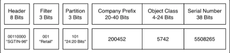
Header 8 Bits Company Prefix 20-40 Bits Object Class 4-24 Bits Serial Number 38 Bits Filter 3 Bits Partition 3 Bits 00110000 "SGTIN-96" 200452 5742 5508265 101 "24:20 Bits" 001 "Retail"
Fig. 1.Electronic Product Code (SGTIN-96 Example)
2.1 ONS Principles
The task of ONS is the retrieval of dynamic lists of Web addresses of (usually) manufacturer EPC Information Services (EPCIS) [6] for specific EPC identifiers. Those identifiers, e.g. the 96 bit SGTIN-96 variant in Fig. 1, uniquely identify items and are stored on attached RFID tags compatible to the EPC standard [7] (which we will call EPC tags in the following). The most important parts of such an EPC are Company Prefix, which corresponds to an EAN.UCC Company Prefix and identifies the owner of the prefix – the EPC Manger (usually the item manufacturer), Object Class, which can be assigned by the manufacturer and describes the item category, and Serial Number, which differentiates between similar objects of the same category.
Besides SGTIN-96, the EPC standard also defines several other encoding schemes: GID-96, SGTIN-198, SGLN-96 etc. The choice of a scheme may depend on the application scenario and a company’s preferences. In the rest of paper we will be referring to the SGTIN-96 scheme, however, due to the structural similarity of the EPC encoding schemes, proposed solutions are applicable to all the schemes described in the EPC specification.
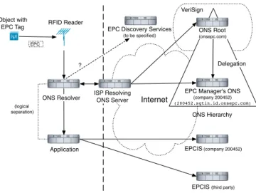
The ONS and the related, but not yet fully specified EPCIS Discovery Ser-vices [1], allow for high flexibility in the linking of physical objects equipped with simple EPC tags and the information about those objects. This information can be stored in various internal or external databases, and can be shared over the Internet using EPCIS, especially those offered by the object manufacturer or by various stakeholders in the supply chain. The list of information sources can easily be updated to include new EPCIS or to change addresses of existing ones, without any change to the anticipated masses of EPC tags deployed in the field. The inner workings of the ONS are described in [2], for an example query procedure see Fig. 2. Since EPCglobal standards make use of general roles to describe system functionality, we give a short specific example – the arrival of a new RFID-tagged good in a shop. An RFID reader located in the delivery area of the shop reads out the tag and receives an EPC identifier in binary form. Then it forwards the EPC identifier to a local inventory system. This inventory system needs to retrieve item information from the manufacturer’s database on the Internet, e.g. to verify the item is fresh and genuine, and to enhance smart advertisement throughout the shop. The system hands the EPC identifier over to a specific software library, the local ONS resolver, which translates the
Internet Object with
EPC Tag RFID Reader
EPC
ONS Hierarchy
EPCIS (company 200452)
EPCIS (third party) ONS Root (onsepc.com)
EPC Manager's ONS (company 200452) (200452.sgtin.id.onsepc.com)
Application
EPC Discovery Services (to be specified)
VeriSign
Delegation
(logical separation)
ONS Resolver ISP ResolvingONS Server ?
Fig. 2.ONS Resolution
identifier into a domain name compatible with the Domain Name System (DNS, for details of its working see Section 3), e.g. 5742.200452.sgtin.id.onsepc. com. This name, which does not make use of the EPC Serial Number as of now, is an element of the DNS domainonsepc.com that has been reserved for ONS and is used for delegation purposes. The resolver queries the resolving ONS server of its organization or Internet Service Provider (ISP). If the EPCIS address list is not known yet (as in our example of a new item) or has been retrieved and cached before, but is now considered as potentially out-of-date, the ONS Root is contacted. This ONS Root, a service run exclusively by the company VeriSign [3], recognizes the Company Prefix part of the DNS-encoded EPC identifier, and delegates the query to the EPC Manager’s ONS server, which has the authoritative address of the manufacturer EPCIS stored in a DNS record called Naming Authority Pointer (NAPTR). Once this address has been determined, the shop inventory system can contact the manufacturer EPCIS directly, e.g. by the use of Web services. To locate different EPCIS for additional information, the use of so-called EPCIS Discovery Services is planned, which are not specified at the time of this writing. However, as is indicated by [1], these search services will (at least in part) be run by EPCglobal.
2.2 ONS and Multipolarity
The ONS Root will formally be under control of the international consortium EPCglobal, but practically run by the U.S.-based company VeriSign. We abstract from these particular circumstances to a more general scenario. Let the ONS Root, as it is designed today, be controlled by a single companyC belonging to a nation or group of closely allied nations N. At any given time and state of
global politics, there exists the possibility for the government(s) ofN to influence those actions ofCthat concern international relationships – this influence can be exerted either directly via laws, or indirectly via political or economic pressure.
Attack Model: Unilateral ONS Blocking. The current design of the ONS would
allowN the following unilateral blocking attack against another nationF: The ONS Root can be easily configured to formally deny any information to clients originating in F (compliant to the ONS protocol), or simply ignore any query from IP addresses belonging toF. An even more efficient way would be to drop inbound ONS packets from F at border routers ofN. The result of this attack would be stalled information at all companies inF. Cached addresses of EPCIS could still be used, but cannot be easily updated anymore. To recover,F may consider building its own version of an ONS Root answering all local queries. However, to feed this new root information from alternative external sources would be tedious and probably very time-consuming. There would be serious business drawbacks for companies inF during that time. Companies outside of F, for example in N, would only (and in the worst case for N) be affected if they heavily rely on business withF (due to retaliate blocking of EPCIS access from N by F or stale data at the ONS Root) – this corresponds to a virtual embargo situation. All other companies would not directly be affected, leading to a comparatively low risk forN. In a highly connected global economy based on the EPCglobal network this kind of attack, or even its threat, could be highly effective and more efficient than a simple general disruption of the global system. This should be prevented already by a design that spreads out the control of the ONS Root more evenly.
Attack Model: Traffic Eavesdropping and Analysis.ONS queries and responses
are transmitted in plaintext and can easily be read by an adversary who is able to intercept them [8]. The control over the ONS Root allows N to eavesdrop on all ONS queries reaching the root nameservers and to gather global business intelligence about location and movements of items tagged with EPC tags vir-tually for free and without risk. Such attacks are relatively easy to launch, both technically and legally1, and could force parties concerned with their privacy to
refuse ONS adoption and to look for alternative solutions.
Before we discuss our design proposals to mitigate these attacks in section 4, we first have to take a deeper look at the origin and inner workings of DNS in the next section.
3
ONS vs. DNS Root Control
3.1 DNS Principles
The basic application of the DNS is the resolution of human-memorizable, alpha-numerical hostnames into the corresponding purely alpha-numerical Internet Protocol
1 According to a recently accepted amendment to Foreign Intelligence Surveillance Act
(FISA), U.S. intelligence is allowed to intercept electronic communication between U.S. and non-U.S. bodies if the communication passes across U.S.-based networks (Protect America Act of 2007).
(IP) addresses used for datagram routing. At an early stage of the Internet, the ARPANET, name resolution was performed by referring to a flat text file that stored mappings between the hostnames and the IP addresses. Obviously, main-taining and synchronizing copies of the hosts files on all computers connected to ARPANET was extremely inefficient. To address this issue, the name resolution protocol was updated to introduce a central distribution of the master hosts file via an online service maintained by the Network Information Center. This architecture worked successfully for about a decade. However, the rapid growth of the Internet rendered this centralized approach impractical. The increasing number of changes introduced to the hosts file and its growing size required hosts to regularly download large volumes of data and often led to propagation of network-wide errors.
As a reaction, shortly after deployment of TCP/IP, the new Domain Name System (DNS) was introduced (classical RFCs include 1034, 1035, see [9]). A hostname now has a compound structure and consists of a number of labels separated by dots, e.g. www.example.com.(the final dot is often omitted). The labels specify corresponding domains: the empty string next to the rightmost dot corresponds to theroot domain, the next label to the left to thetop-level domain
(TLD), followed by thesecond-level domain (SLD) and so forth. The resolution
of the hostname into the corresponding IP address is carried out by a tree-like hierarchy of DNS nameservers. Each node of the hierarchy consists of DNS nameservers that store a list ofresource records (RRs) mapping domain names into IP addresses of Internet sites belonging to azonefor which the DNS servers are authoritative. Alternatively, in case of zone delegation, IP addresses of DNS servers located at the lower levels of the hierarchy are returned. The resolution of a hostname is performed by subsequently resolving domains of the hostname from right to left, thereby traversing the hierarchy of the DNS nameservers until the corresponding IP address is obtained.
In practice, not every resolution request has to traverse the whole hierar-chy. To reduce the load on the DNS, nameservers use a caching mechanism. For a limited period of time called time to live (TTL), DNS resolvers and servers store results of successful DNS queries in a local cache and, when possible, reuse those instead of delegating or issuing queries to other DNS servers. The detailed coverage of DNS mechanism and operations is out of scope of this paper. The in-terested reader can consult the plethora of existing DNS-related RFCs compiled in [9] and standard literature [5] for more details.
3.2 DNS and Multipolarity
As we outlined above, the DNS is a hierarchy of DNS nameservers, each respon-sible for resolving hostnames of Internet sites belonging to its zone or pointing to another DNS nameserver if delegation takes place. DNS nameservers author-itative for TLDs (e.g. .eu, .com) are operated by domain name registries – organizations responsible for managing and technical operation of the TLDs. The root nameservers are operated by governmental agencies, commercial and
profit organizations. The root zone is maintained by the U.S.-based, non-profit Internet Corporation for Assigned Names and Numbers (ICANN). ICANN was contracted for this purpose by the U.S. Department of Commerce, which thereby holdsde jure control over the root namespace. Currently the root zone is served by only 13 logical root nameservers, whose number cannot be increased easily due to technical limitations. However, many of those servers are in fact replicated across multiple geographical locations and are reachable via Anycast2.
As a result, currently most of the physical root nameservers are situated outside of the U.S. [10].
However, the concentration of de jure control over the root namespace in hands of a single governmental entity is subject to constant criticism from the Internet community. In theory, this entity has the power to introduce any changes to the root zone file. However, due to the de facto dispersal and replication of the root zone, such changes have to be propagated among all the other root nameservers, many of which are beyond the authority of the entity controlling the root zone. In case the entity decides to abuse its power and introduces changes in the root zone by pursuing solely its own benefits, some of the root nameservers may refuse to introduce the changes into their root zone files, which, in the end, may lead to the uncontrolled and permanent fragmentation of the Internet, undermining its basic principles and increasing business risk globally.
These consequences, as well as the fact that such changes have not occurred until now, allow to assume that the Internet is not directly dependant on the entity managing the root namespace, and that it is highly unlikely for this entity to introduce any changes impeding fair and global Internet access. As a conse-quence, the Blocking Attack is not realistic with DNS without severe risks to the initiating country.
4
MONS – Multipolar ONS
In this section we propose modifications of the current ONS architecture that would allow to distribute the control over the ONS root between several inde-pendent parties, thus, solving the issue of unilateral root control.
4.1 Replicated MONS
One of the main reasons why the DNS was chosen for implementing the EPC resolution is, probably, the alleviation of effort required to introduce the ONS on a global scale: The DNS is considered by many practitioners as a mature and time-proven architecture.3 Its choice allows to deploy the ONS using existing
DNS software and rely on best practices accumulated during decades of the DNS being in use. As a result, the deployment of a local ONS nameserver can
2 Anycast is a routing scheme that allows to set up one-to-many correspondence
be-tween an IP address and several Internet sites so that when an actual communication takes place the optimal destination is chosen (for DNS use cf. RFC 3258).
be relatively easily performed by a system administrator with DNS experience using freely available software. Thus, if we want to modify the existing ONS architecture, it makes sense to stay consistent with the DNS protocol.
The ONS root will run on six locally distributed server constellations, all operated by VeriSign [3] (Fig. 3(a)). This strongly contrasts with the DNS ar-chitecture, where the root nameservers are operated also by numerous other entities [10]. A straightforward approach to avoid the unipolarity of the ONS is to replicate the ONS root between a number of servers operated by independent entities, and to synchronize the instances of the root zone file with a master copy published by EPCglobal. To restrict the amounts of incoming queries, each root nameserver could be configured to cover a certain area in the IP topology and respond only to queries originating from there.
Such replicated ONS root nameservers could provide their services in parallel with the global ONS root operated by VeriSign. The resolving ONS servers of organizations and Internet Service Providers (ISP) should be configured on the one hand with the domain name or IP address of the global ONS root (onsepc.com), or, more efficiently, the server responsible for SGTIN (sgtin. id.onsepc.com), on the other hand also with the corresponding replicated ONS server (e.g. sgtin.id.onsepc-replication.eu), potentially avoiding Anycast constructions like those used as later add-ons for DNS.
To evaluate the feasibility of this approach and the amount of data that has to be replicated, we approximately calculate the size of the ONS root zone file by estimating the number of RRs stored there, which define mappings between Company Prefixes and domain names of the corresponding ONS nameservers. Today, there are about one million registered Company Prefixes.4 We assume
that at a certain time in future most of them will have corresponding EPCIS services. The ONS root zone file is a plain text file consisting of a number of NS RRs. As an example, consider an EPC number 400453.1734.108265 that can be resolved into one of two ONS nameservers:
1737.400453.sgtin.onsepc.com IN NS ons1.company.com 1737.400453.sgtin.onsepc.com IN NS ons2.company.com
IN stands for Internet, and NS indicates that the record defines a nameserver authoritative for the domain. The number of nameservers responsible for the same zone cannot exceed thirteen, and the DNS specification recommends having at least two. In practice, however, their number usually varies from two to five. Assuming the average number of ONS nameservers per company (N) as four, the average length of an NS record (L) as 60 symbols, and that one symbol takes one byte, and the number of registered Company Prefixes (P) as one million, we can roughly estimate the size of the ONS root zone file containing the RRs for all currently registered EAN.UCC Company Prefixes asN×L×P, which is slightly above 200 megabytes. By using compression a text file may be reduced to 10-20% of its original size. Thus we conclude that the distribution and regular renewal of the root file presents no technical difficulties. The master root file can
ONS Root Nam!server (VeriSign)
EPC Managers' Nameservers
. . .
(a) Current ONS
. . . ONS Root File Provider (EPCglobal) Replicated ONS Root
Nameservers
EPC Managers' Nameservers . . .
Primary ONS Root Nameserver
(VeriSign)
(b) Replicated MONS
EPC Managers' Nameservers
. . .
Region 1 Region 2 Region N
. . . . . . . . .
Regional MONS Root Nameservers
(c) Regional MONS
Fig. 3.MONS Architectures
be shared between ONS roots by the means a simple file transfer or a peer-to-peer file sharing protocol. The architecture is illustrated at Fig. 3(b) and will be further referred to as Replicated MONS.
The key requirement of Replicated MONS is the public availability of the ONS root file. As soon as the root file is published and regularly updated, the replicated roots can be deployed independently from each other. In case those new roots will be configured to cover only certain areas, locations beyond their bounds will still be able to use VeriSign’s nameservers, remaining vulnerable to the Blocking Attack.
4.2 Regional MONS
The architecture described in the previous section provides a solution which allows any entity to maintain a copy of an ONS root nameserver, enhancing the availability of the ONS. However, due to the necessity to cope with a high load, such nameservers might not be accessible globally, potentially resulting in a (from a global perspective) unstructured patchwork of areas with ONS root redundancy. The high load on the root nameservers will be mainly caused by the size and frequent updates of the root zone file. Compared to the DNS root zone file, which contains RRs on about 1500 TLD nameservers and currently has a size of about 68 kilobytes5, the ONS root zone file will contain RRs forall EPC
Managers’ ONS nameservers registered at EPCglobal. With RFID becoming
Internet
Object with
EPC of Region n RFID Reader
EPC
EPCIS (Manufacturer) MONS Regional Root for Region n
EPC Manager's ONS in Region n ONS Resolver
Client in Region m
Application
Regional MONS Root for Region m 1 2 3 4 (logical separation) ISP Resolving ONS Server
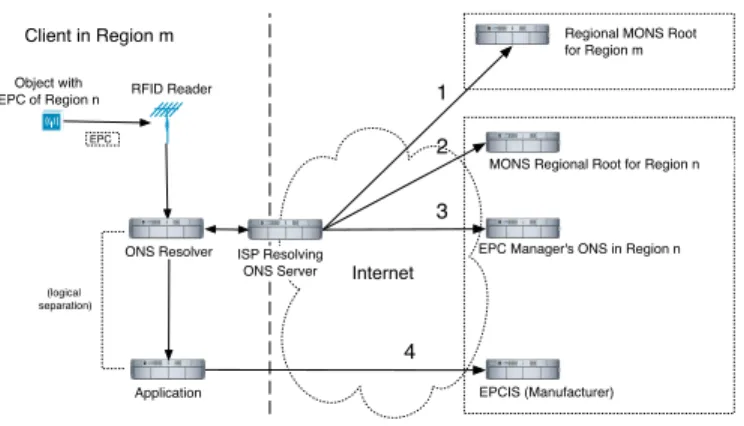
Fig. 4.Regional MONS Resolution
ubiquitous, their number is expected to grow rapidly, resulting in millions of RRs. Also, due to a higher volatility of ONS root RRs, their TTL parameters might be assigned lower values as compared to the RRs of the DNS root. As a result, the ONS RRs will be cached for shorter periods of time and a larger number of queries will be reaching the ONS root nameservers.
In this section we suggest a more radical alteration of the existing ONS archi-tecture that will allow to reduce the size of the root zone file and the frequency of its updates by splitting it between a number of regional root nameservers, at the same time offering a structured way to achieve area coverage for redun-dancy. A zone file of each regional nameserver contains RRs that correspond to EPC Managers belonging to a region for which a nameserver is authoritative. The membership to a region might be determined by a company’s registration address, regional GS1 department that issued the Company Prefix, or other properties.
The architecture is depicted in Fig. 3(c), while the resolution process is pre-sented in Fig. 4. In case the resolving nameserver and the EPC Manager (who corresponds to the EPC being resolved) belong to the same region (n = m), the step 2 is omitted and the resolution process is almost identical to the one depicted in Fig. 2: The regional root nameserver delegates the query to the name-server of the EPC Manager which returns the address of the EPCIS. However, ifn"=m, the query is redirected to the regional root nameserver authoritative for the Region n(step 2), which in turn delegates it to the nameserver of the EPC Manager. We will refer to this architecture asRegional MONS.
Compared to the ONS resolution process described in Section 2.1, the case of the delegation of a query from one regional ONS nameserver to another (step 2) introduces an additional resolution step. Consequently, this requires an extension of the EPC scheme and the introduction of a new prefix that will be resolved at this step. Following the approach for constructing an EPC, a natural choice would be aregional prefix pointing to a country or a region of origin for a given product. The introduction of this regional prefix requires an update of the EPC
EPC Managers' Nameservers
. . .
Region 1 Region 2 Region N
. . . . . . . . .
MONS Relative Root
Fig. 5.Relative Hierarchy of Regional MONS Nameservers
encoding standards, which might result in a lengthy and costly process. However, the EPC encoding schemes defined in [7] already contain enough information to unambiguously associate an EPC with a certain region. The first three digits of the EAN.UCC Company Prefix identify the country of GS1 membership for the company (e.g. codes 400-440 are reserved for Germany). Therefore, an alternative to the introduction of a new regional prefix field would be to use these digits for associating EPC identifiers with corresponding regions. Each regional root nameserver will be responsible for one or several regional prefixes.
Note that a resolver still sees the Regional MONS architecture as a hierarchy: The MONS root of its region is being perceived as the root of the whole hierarchy (Fig. 5). We call such a structure a relative hierarchy. A regional nameserver authoritative for a region from which the resolution takes place is called its
relative root. This allows to implement the Regional MONS within the DNS
framework, reflecting the approach described in the ONS specification.
In the following, we assume that the regional prefix is defined as the first three digits of the Company Prefix. To access an EPCIS that could provide data about a given EPC identifier, the identifier is again translated into a DNS-compatible address, but now the first three digits of the Company Prefix have to be explicitly separated by dots and placed to the right of the rest of the inverted EPC identi-fier (e.g.1734.453.400.sgtin.id.onsepc.com). Assume that the domain name of the regional nameserver authoritative for zone400.sgtin.id.onsepc.comis ns1.mons.eu. An ONS client physically located at the same region is configured to sends all its ONS queries to ns1.mons.eu (step 1 at Fig. 4), which it views as the relative root of the Regional MONS. Correspondingly, a resolver that belongs to a different region will be configured with the address of a different regional root, also viewed as relative root. In this example we deliberately choose the domain name of the regional root to have the TLD (.eu) corresponding to the region of its authority. This avoids the dependency on entities administering regional nameservers domains and excludes the possibility of a Blocking Attack from their side. Note, that the resolution process described above does not re-quire an EPC identifier to be translated to the domain name resolvable by the DNS of the Internet. The only domains relevant to the ONS resolution are the dot-separated EPC identifier and the domain pointing out in which format an
EPC number is stored. This makes the three rightmost domains abundant since 1734.453.400.sgtinis already sufficient for unambiguous ONS resolution.
By appointing specific nameservers to regions, Regional MONS naturally shifts the load to nameservers authoritative for economically developed or indus-trial countries, since regional prefixes of such regions will occur on the majority of the EPC identifiers. Moreover, regions whose export values are too low, or who are not interested in maintaining their own Regional MONS root nameservers could delegate this responsibility to third parties, as it is sometimes done with country code TLDs [10]. Once their situation changes, they can take back their reserved share of the system by a minor change in the table of Regional MONS Roots (MONS Root Zone).
4.3 Regional MONS Prototype
In this section we present a possible fragment of the Regional MONS architecture implemented using BIND DNS Server software. BIND (Berkeley Internet Name Domain) is the most common DNS server in the Internet and thede facto stan-dard for Unix-based systems. ONS can be deployed using stanstan-dard DNS software, so it is very likely that a considerable portion of ONS nameservers will be using BIND. In our sample scenario we consider two regions with regional codes 400 and 450 and two EPCISs, each providing information about one of the following SGTIN formatted EPC identifiers: 400453.1734.108 and 450321.1235.304.
The main configuration file of a BIND server is the named.conf. RRs for namespaces are stored in zone files often namednamespace.db. Fig. 6 presents a possible configuration of four ONS nameservers that constitute this fragment of the Regional MONS hierarchy. The fragment includes two regional MONS root nameservers authoritative for regional prefixes 400 and 450, correspondingly, and two nameservers of EPC Managers.6 The regional roots are configured as
relative roots of the sgtin zone and as authorities for the respective regional codes (400.sgtinand450.sgtin, correspondingly). Thesgtin.dbfile describes the relative root zone (sgtin) by declaring the nameserver as the authority for this zone and referring to the content of onsroots.dbfile, which represents the MONS Root Zone. This file is the same for all regional roots and defines the delegation of the zones (using the regional codes) to the regional roots. The RRs of the400.sgtin.dband450.sgtin.dbfiles introduce a further delegation step by pointing to the nameservers of the respective EPC Managers that complete the resolution process by returning the URI of the requested EPCIS via NAPTR RR. To make the zone files less dependent on infrastructure changes in the MONS hierarchy, they may contain only NS records without mentioning the corresponding IP addresses in A records. So, if one or several nameservers has its IP address changed the zone files still remain consistent. However, this can prolong the resolution process, since ONS nameservers will have to query the DNS to resolve domain names to IP addresses.
··· 400.sgtin. IN NS ns1.ons.eu. 450.sgtin. IN NS ns1.ons.jp ns1.ons.eu. IN A 169.257.50.3 ns1.ons.jp. IN A 123.108.4.46 ··· onsroots.db ··· zone "sgtin" { type master; file "/etc/bind/zones/sgtin.db";}; zone "400.sgtin" { type master; file "/etc/bind/zones/sgtin.400.db";}; ··· named.conf ··· sgtin. IN NS ns1.ons.eu. ns1.ons.eu. IN A 169.257.50.3 ··· $INCLUDE /bind/zones/onsroots.db sgtin.db ··· 400.sgtin. IN NS ns1.ons.eu. ns1.ons.eu. IN A 169.257.50.3 453 IN NS ns1.manufact_a.com ns1.manufact_a.com. IN A 195.71.13.3 ··· 400.sgtin.db ··· zone "453.400.sgtin" { type master; file "/etc/bind/zones/453.400.sgtin.db";}; ··· named.conf ··· 1734 IN NAPTR 0 0 "u" "EPC+epcis"
"!^.*$!http://manufact_a.com/epcis!" . ··· 453.400.sgtin.db ··· zone "sgtin" { type master; file "/etc/bind/zones/sgtin.db";}; zone "450.sgtin" { type master; file "/etc/bind/zones/sgtin.450.db";}; ··· named.conf ··· sgtin. IN NS ns1.ons.jp. ns1.ons.jp. IN A 123.108.4.46 ··· $INCLUDE /bind/zones/onsroots.db sgtin.db ··· 450.sgtin. IN NS ns1.ons.jp. ns1.ons.jp. IN A 123.108.4.46 321 IN NS ns1.manufact_b.com ns1.manufact_b.com. IN A 210.18.2.10 ··· 450.sgtin.db ··· zone "321.450.sgtin" { type master; file "/etc/bind/zones/321.450.sgtin.db";}; ··· named.conf ··· 1235 IN NAPTR 0 0 "u" "EPC+epcis"
"!^.*$!http://manufact_b.com/epcis!" . ··· 321.450.sgtin.db Regional MONS root nameserver ns1.ons.eu IP address: 169.257.50.3 Regional MONS root nameserver ns1.ons.jp IP address: 123.108.4.46 EPC Manager's nameserver ns1.manufact_a.com IP address: 195.71.13.3 EPC Manager's nameserver ns1.manufact_b.com IP address: 210.18.2.10 EPCIS http://manufact_b.com/epcis EPCIS http://manufact_a.com/epcis
Fig. 6.Fragment of Regional MONS Hierarchy
4.4 Modularity
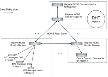
One further advantage of Regional MONS is that each region could implement different resolution architectures for its own subsystem below the root zone. For example (see Fig. 7), a regionrcould use the original ONS specification based on the DNS, another regionncould use a centralized search system, while yet other regions, like m, could implement subsystems based on Distributed Hash Tables (DHT), e.g. the OIDA system proposed in [4]. Delegation between MONS and heterogeneous subsystems can be established by bridging nodes that are able to use both protocols. In the DHT case for example, a DHT node queried by external DNS clients uses the DNS protocol to answer. However, to communicate with other DHT nodes, the specific overlay network communication is used, for
Regional MONS Root for Region n Regional MONS
Root for Region r
Central Common Database for for Region n
Regional MONS Root for Region m Regional EPCIS Discovery Service for Region m
DHT Region m
EPC Manager's ONS in Region r
EPC Manager's ONS in Region r
EPC Manager's ONS in Region r
...
...
...
MONS Root Zone Query DelegationFig. 7.Modularity of MONS Subsystems
example as defined in Chord [12]. This combination of DNS and DHT has been successfully implemented for general DNS use, for example in CoDoNS [11].
5
MONS Data Authenticity
Today’s Internet has to be regarded as a highly insecure environment, a fact that has been acknowledged not only by the security community, but also po-litical institutions [13]. Surprisingly, security measures have not been considered intrinsically from the beginning in the EPCglobal architecture standards [8], but seem to be held as optional and mostly to be added later by its users [1]. Besides availability and confidentiality risks of the EPCglobal Network and the ONS in particular, a major concern is the lack of authentication methods in the cur-rent ONS standard [2]. Without additional security measures, global business systems depending on the ONS, as it has been designed in the standard so far, could suffer from cache poisoning and man-in-the-middle attacks [14], leading to spoofed EPCIS address information, and potentially also to forged EPC informa-tion, or via additional vulnerabilities, malware infection initiated by malicious servers. Adding countermeasures like DNS Security Extensions (DNSSEC) later, however, will also have an impact on properties of the whole system, like per-formance, security and privacy, as well as in our case, multipolarity.
In this section we first take a short look at the recent DNSSEC standards, discuss how DNSSEC could be used in a straightforward way to secure ONS data, leading to a substructure of DNSEC we propose to call ONSSEC. Finally we suggest mechanisms to achieve multipolarity for ONSSEC, thereby enabling its use for MONS (short for Regional MONS from now on).
5.1 DNSSEC
To address the lack of authentication in the DNS, a set of mechanisms called DNSSEC (DNS Security Extensions) has been designed, the recent version being presented in [15] and related other RFCs. The DNSSEC provides data integrity and authenticity for the delivered DNS information by using public-key cryp-tography to sign sets of resource records (RRs). It uses four resource record types: Resource Record Signature (RRSIG), DNS Public Key (DNSKEY), Del-egation Signer (DS), and Next Secure (NSEC), the last one is used to provide authenticated denial of existence of a zone entry, for details cf. [15]. Each DNS zone maintainer is also responsible for providing a signature of those zone files. These signatures are stored in an RRSIG record. The server’s public key could be transferred out-of-band, or be stored and delivered via DNS itself using an RR of type DNSKEY.
The use of separate zone-signing and key-signing keys enables easy resigning of zone data without involving an administrator of the parent zone [5]. However, having a signature and an apparently corresponding public key does not guaran-tee authenticity of the data – the public key and identity must be securely linked by a trusted entity, most practically, by the maintainer of the respective parent zone. To be able to verify an arbitrary DNS public key in a scalable way, chains of trust down from the (necessarily trusted) root of the DNS would be necessary, where each parent DNS server signs the keys of its children, after having verified its correspondence to the correct identity by some external means.
Even after a major redesign of the protocol (and its RRs) in 2005, cf. RFC 4033 [15] (which replaces RFC 2535 from 1999 that in turn obsoleted the original RFC 2065 dating from 1997), DNSSEC is not yet widely established throughout the Internet, though recent developments like the signing of some countries’ TLD seem to indicate a brighter perspective for DNSSEC [16]. Reasons for the slow DNSSEC adaption include, first of all, reluctance to major changes for critical services like DNS, scalability problems of key management, the administrative problem of building chains of trust between servers of many different organiza-tions. There also is the problem of establishing a critical mass of DNSSEC users with different incentives [17]. Despite these problems, the establishment of a new global business architecture like the EPCglobal Network could be a major op-portunity to launch ONSSEC, the adaption and restriction of DNSSEC to ONS use. However, DNSSEC suffers from a major unipolarity problem: Who should control the anchor of trust, the keys for the root zone? This problem must be solved for a multipolar ONS, to avoid unwanted indirect unipolarity for MONS introduced by its security extensions.
5.2 ONSSEC
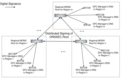
DNSSEC can be applied to MONS as follows, cf. Fig. 8: Each Regional MONS Root provider signs the key-signing keys of all EPC Managers in its region. This is major administrative task and has to involve the verification of the EPC Manager’s identity. This procedure is, however, less cumbersome then signingall
Regional MONS Root for Region n Regional MONS
Root for Region r
Regional MONS Root for Region m
EPC Manager's ONS in Region r
EPC Manager's ONS in Region r
EPC Manager's ONS in Region r
...
...
...
Distributed Signing of ONSSEC Root Digital SignatureEPC Manager's ONS in Region n
EPC Manager's ONS in Region n EPC Manager's ONS in Region n
EPC Manager's ONS in Region m
EPC Manager's ONS in Region m EPC Manager's ONS in Region m
Fig. 8.Multipolar ONSSEC Trust Structure
subdomain keys of a given TLD, rendering ONSSEC introduction more scalable than general DNSSEC where probably also more delegation steps are involved. The EPC Managers then are able to sign their own zone-signing keys and the ac-tual zone data. They can repeat the latter procedure after each change in zone data without contacting the regional root; they are also able to periodically change their zone-signing keys for better long-term security. The EPC Man-ager’s nameservers can now answer MONS queries by returning the actual zone information in combination with the signature. This signature can be verified by a client by retrieving the public key of the regional MONS root. Here another (cf. section 4.3), bigger problem of using the flexible option of general DNS names in (M)ONS resource records becomes apparent (e.g. in URIs of NAPTR records for EPCIS, see Fig. 6): Without an established global trust structure and ubiquitous use of DNSSEC, arbitrary DNS names and resolution steps would not easily be covered by authentication measures. As long as this situation holds, the tradeoff between flexibility vs. lack of authenticity needs to be constantly evaluated.
With the described Regional MONS architecture, there would be multiple roots of trust. This situation could be impractical, because clients who often resolve EPCs of foreign regions would have to trust multiple public keys, those of the local and all foreign regional MONS roots. With DNSSEC, it is often stated as best practice that a single entity should control the root zone key signing keys. It is, however, subject to current international debate, which organization should represent this entity – for example, interest has been expressed by US authorities like the Department of Homeland Security [18]. A similar problem exists for the MONS root zone (the onsroots.db of the prototype in section 4.3). In the following section, we briefly discuss options for a solution.
5.3 Multipolarity for the ONSSEC Root
Multipolarity for the root key control of ONSSEC (that is DNS Security Exten-sions applied to (M)ONS) could be achieved by multiple signatures (each regional MONS root would sign the root zone) [19], or more elegantly and scalably, by the use of one virtual ONSSEC root by applying threshold cryptography. An(n,
t)-threshold cryptography schemeallowsnparties to share the ability to perform
a cryptographic operation (e.g., applying a digital signature), so thatt (t≤n) parties can perform this operation jointly, but at mostt−1 (malicious) parties are not able to do so, even by collusion [20, pp. 525]. Famous threshold secret sharing schemes include [21], using polynomial interpolation, and [22] based on intersection of n-dimensional hyperplanes. Secret sharing could be used to share the private key of the virtual ONSSEC root, but once used the whole private key might become compromised.
More secure are threshold function sharing schemes, extensions of the basic secret sharing, which allow for digital signatures without letting a single party know the complete key during operations, see e.g. [23, 24] for schemes with usable performance properties. The signing of the regional root keys and the MONS root zone should be quite a rare operation in comparison to the signing of actual manufacturer zone data. Therefore, these schemes could be implemented without major performance penalties on the whole system. In summary, using threshold cryptography would enable the distributed and multipolar signing of the MONS regional root keys (Fig. 8), as well as the MONS root zone that contains address data of all Regional MONS Roots.
6
Conclusion and Future Research
In this paper we presented MONS, a practical architecture to achieve multipo-larity in the ONS. We also showed how multipomultipo-larity in corresponding authen-tication extensions can be achieved. To our knowledge, this is the first extensive discussion and solution proposal of the multipolarity problem for ONS, which in a future ”Internet of Things” may have even more detrimental consequences than the analogous problem currently debated for DNS [19]. We focus so far on a technical perspective, where our future work will include a sample implemen-tation of distributed signing of the ONSSEC root zone, which may also become relevant for DNSSEC. On the policy side, analysis of the practical political and administrative challenges of distributing control over the ONS is an important line for future research. Not last, there is urgent need to solve further multilat-eral security problems of ONS and related systems like MONS, especially their possible impact on corporate and individual privacy.
References
1. EPCglobal: The EPCglobal Architecture Framework – Version 1.2. Ed. by Traub, K. (September 2007)
2. Mealling, M.: EPCglobal Object Naming Service (ONS) 1.0 (2005)
3. EPCglobal: Implementation of the EPCglobal Network Root ONS. EPCglobal Position Paper (November 2005)
4. Fabian, B., G¨unther, O.: Distributed ONS and its Impact on Privacy. In: Proc.
IEEE International Conference on Communications (IEEE ICC 2007), Glasgow. (2007) 1223–1228
5. Liu, C., Albitz, P.: DNS and BIND. 5th edn. O’Reilly & Associates (2006) 6. EPCglobal: EPC Information Services (EPCIS) Version 1.0 Specification (April
2007)
7. EPCglobal: EPC Tag Data Standards Version 1.3 (2006)
8. Fabian, B., G¨unther, O., Spiekermann, S.: Security Analysis of the Object Name
Service. In: Proceedings of the 1st International Workshop on Security, Privacy and Trust in Pervasive and Ubiquitous Computing (SecPerU 2005), with IEEE ICPS 2005, Santorini. (2005) 71–76
9. Salamon, A.: DNS related RFCs. http://www.dns.net/dnsrd/rfc/
10. Gibbard, S.: Geographic Implications of DNS Infrastructure Distribution. The
Internet Protocol Journal10(1) (2007) 12–24
11. Ramasubramanian, V., Sirer, E.G.: The Design and Implementation of a Next Generation Name Service for the Internet. In: SIGCOMM ’04: Proceedings of the 2004 conference on Applications, technologies, architectures, and protocols for computer communications, New York, NY, USA, ACM Press (2004) 331–342 12. Stoica, I., Morris, R., Liben-Nowell, D., Karger, D.R., Kaashoek, M.F., Dabek, F.,
Balakrishnan, H.: Chord: A Scalable Peer-to-peer Lookup Protocol for Internet
Applications. Networking, IEEE/ACM Transactions on11(1) (2003) 17–32
13. PITAC: Cyber security - a crisis of prioritization.http://www.nitrd.gov/pitac/
reports/20050301 cybersecurity/cybersecurity.pdf(February 2005)
14. Atkins, D., Austein, R.: Threat Analysis of the Domain Name System (DNS). Request for Comments - RFC 3833 (2004)
15. Arends, R., Austein, R., Larson, M., Massey, D., Rose, S.: DNS Security Introduc-tion and Requirements. Request for Comments - RFC 4033 (March 2005) 16. Friedlander, A., Mankin, A., Maughan, W.D., Crocker, S.D.: DNSSEC: A Protocol
toward Securing the Internet Infrastructure. Commun. ACM50(6) (2007) 44–50
17. Ozment, A., Schechter, S.E.: Bootstrapping the Adoption of Internet Security Pro-tocols. In: Proc. of the Fifth Workshop on the Economics of Information Security (WEIS 2006). (2006)
18. Leyden, J.: Homeland Security Grabs for Net’s Master Keys. http://www.
theregister.co.uk/2007/04/03/dns master key controversy/(2007)
19. Kuerbis, B., Mueller, M.: Securing the Root: A Proposal for Distributing Signing Authority. Internet Governance Project Paper IGP07-002 (2007)
20. Menezes, A.J., van Oorschot, P.C., Vanstone, S.A.: Handbook of Applied Cryp-tography. CRC Press (1997)
21. Shamir, A.: How to Share a Secret. Commun. ACM22(11) (1979) 612–613
22. Blakley, G.R.: Safeguarding Cryptographic Keys. In: Proc. of the National Com-puter Conference. Volume 48. (1979) 313–317
23. Shoup, V.: Practical Threshold Signatures. In: Advances in Cryptology - EU-ROCRYPT 2000. Proc. International Conference on the Theory and Application of Cryptographic Techniques, Bruges, Belgium, May 14-18, 2000. Volume LNCS 1807., Springer (2000) 207–220
24. Kaya, K., Sel¸cuk, A.A.: Threshold Cryptography based on Asmuth-Bloom Secret