ECMA-349
4th Edition – June 2008Data Interchange on
120 mm and 80 mm
Optical Disk using
+R Format
–
Capacity:
4,7 and 1,46 Gbytes
per Side
Data Interchange on
120 mm and 80 mm
Optical Disk using
+R Format
–
Capacity:
4,7 and 1,46 Gbytes per
Side
(Recording speed up to 16X)
Standard
ECMA-349
4th Edition - June 2008Introduction
Ecma Technical Committee TC31 was established in 1984 for the standardization of Optical Disks and Optical Disk Cartridges (ODC). Since its establishment, the Committee has made major contributions to ISO/IEC toward the development of International Standards for 80 mm, 90 mm, 120 mm, 300 mm, and 356 mm media. Numerous standards have been developed by TC31 and published by Ecma, almost all of which have also been adopted by ISO/IEC under the fast-track procedure as International Standards.
In April 2003 a group of Companies proposed to TC31 to develop a standard for 120 mm recordable optical disks using the WORM recording technology and based on the DVD − Read-Only standard (ECMA-267) and the +RW format (ECMA-337). TC31 adopted this project and started the work that has resulted in the first edition of ECMA-349.
This Ecma Standard specifies two Types of recordable optical disks, one (Type S) making use of recording on only a single side of the disk and yielding a nominal capacity of 4,7 or 1,46 Gbytes per disk and the other (Type D) making use of recording on both sides of the disk and yielding a nominal capacity of 9,4 or 2,92 Gbytes per disk.
In December 2003 a proposal was made to TC31 to update this Ecma Standard for recording speeds up to 8 times the Reference velocity. TC31 adopted this project which has resulted in the second edition of ECMA-349.
In February 2005 a proposal was made to TC31 to update this Ecma Standard for recording speeds up to 16 times the Reference velocity and to facilitate the application of the Video Content Protection System. This Ecma Standard, taken together with a standard for volume and file structure, such as for instance developed in Ecma Technical Committee TC15, provides the requirements for information interchange between systems.
Table of contents
S e c t i o n 1 — G e n e r a l 1 1 S c o p e 1 2 C o n f o r m a n c e 1 2.1 Optical Disk 1 2.2 Generating system 1 2.3 Receiving system 1 2.4 Compatibility statement 1 3 R e f e r e n c e s 2 4 D e f i n i t i o n s 2 4.1 Channel bit 2 4.2 Clamping Zone 24.3 Digital Sum Value (DSV) 2 4.4 Disk Reference Plane 2
4.5 dummy substrate 2 4.6 entrance surface 2 4.7 field 2 4.8 groove 3 4.9 interleaving 3 4.10 mark 3 4.11 Multi-session disk 3 4.12 Physical Sector 3 4.13 recording layer 3 4.14 Reed-Solomon code (RS) 3 4.15 Reference velocity 3 4.16 Single-session disk 3 4.17 session 3 4.18 space 3 4.19 substrate 3 4.20 track 3 4.21 track pitch 3 4.22 VCPS 4
4.23 wobble 4 4.24 zone 4 5 C o n ve n t i o n s a n d n o t a t i o n s 4 5.1 Representation of numbers 4 5.2 Names 4 6 A b b r e vi a t i o n s a n d a c r o n ym s 4 7 G e n e r a l d e s c r i p t i o n o f t h e o p t i c a l d i s k 5 8 G e n e r a l R e q u i r e m e n t s 6 8.1 Environments 6 8.1.1 Test environment 6 8.1.2 Operating environment 6 8.1.3 Storage environment 7 8.1.4 Transportation 7 8.2 Safety requirements 7 8.3 Flammability 7 8.4 Light fastness 7 9 R e f e r e n c e D r i ve 7 9.1 Optical system 7 9.2 Optical beam 8 9.3 Read channel 1 9 9.4 Disk clamping 9
9.5 Rotation of the disk 9 9.6 Wobble channel (Read channel 2) 10 9.7 Tracking channel (Read channel 2) 10 9.8 Reference servo systems 10 9.8.1 Normalized servo transfer function 10 9.8.2 Reference Servo for Axial Tracking 10 9.8.3 Reference Servo for Radial Tracking 11
S e c t i o n 2 — D i m e n s i o n a l , m e c h a n i c a l a n d p h ys i c a l c h a r a c t e r i s t i c s o f t h e d i s k 1 3 1 0 D i m e n s i o n a l c h a r a c t e r i s t i c s 1 3
10.1 Reference Planes 14 10.2 Overall dimensions 14 10.3 First transition area 14 10.4 Second transition area 15
10.6 Third transition area 15 10.7 Information Zone 15 10.8 Rim Area 15 10.9 Remark on tolerances 16 1 1 M e c h a n i c a l c h a r a c t e r i s t i c s 1 6 11.1 Mass 16 11.2 Moment of inertia 16 11.3 Dynamic imbalance 16 11.4 Axial runout 16
11.4.1 Tracking requirements at the Reference velocity (CLV) 16 11.4.2 Tracking requirements at 3 000 RPM (CAV) 16
11.5 Radial runout 17
11.5.1 Tracking requirements at the Reference velocity (CLV) 17 11.5.2 Tracking requirements at 3 000 RPM (CAV) 17
1 2 O p t i c a l c h a r a c t e r i s t i c s i n t h e I n f o r m a t i o n Z o n e 1 7
12.1 Index of refraction 17 12.2 Thickness of the substrate 17
12.3 Reflectivity 18 12.4 Birefringence 18 12.5 Angular deviation 19 S e c t i o n 3 — F o r m a t o f i n f o r m a t i o n 2 0 1 3 D a t a f o r m a t 2 0 13.1 Data Frames 20
13.1.1 Identification Data (ID) 21 13.1.2 ID Error Detection Code (IED) 21
13.1.3 RSV 21
13.1.4 Error Detection Code (EDC) 22 13.2 Scrambled Frames 22
13.3 ECC Blocks 23
13.4 Recording Frames 24 13.5 Modulation and NRZI conversion 24 13.6 Physical Sectors 25 13.7 Layout of a Recording UNit (RUN) 26 13.7.1 Recording Unit position 27 13.8 d.c. component suppression control 27
1 4 T r a c k f o r m a t 2 8
14.2 Track path 28
14.3 Track pitch 29
14.4 Track layout 29
14.4.1 ADIP information 29 14.4.2 Physical format information in ADIP 32
S e c t i o n 4 — F o r m a t o f t h e I n f o r m a t i o n Z o n e 5 2 1 5 G e n e r a l d e s c r i p t i o n o f t h e I n f o r m a t i o n Z o n e 5 2 1 6 L a yo u t o f t h e I n f o r m a t i o n Z o n e o f a S i n g l e - s e s s i o n d i s k 5 2
16.1 Physical Sector Numbers (PSNs) 52
1 7 I n n e r D r i ve A r e a 5 3
17.1 Initial Zone 54
17.2 Inner Disk Test Zone 54 17.3 Count Zone Run-in 54 17.4 Inner Disk Count Zone 54 17.5 Inner Disk Administration Zone 54 17.6 Table of Contents (TOC) Zone 55 17.6.1 Table of Contents Blocks 55 17.6.2 Recorded Area Indicators 58
1 8 L e a d - i n Z o n e 5 8
18.1 Guard Zone 1 58
18.2 Reserved Zone 1 58 18.3 Reserved Zone 2 58 18.4 Inner Disk Identification Zone 59 18.5 Reserved Zone 3 59 18.6 Reference Code Zone 59
18.7 Buffer Zone 1 59
18.8 Control Data Zone 60 18.8.1 Physical format information 60 18.8.2 Disk manufacturing information 62 18.8.3 Content provider information 62
18.9 Buffer Zone 2 62
1 9 D a t a Z o n e 6 2
2 0 L e a d - o u t Z o n e 6 2
20.3 Guard Zone 2 63
2 1 O u t e r D r i ve A r e a 6 3
21.1 Outer Disk Administration Zone 63 21.2 Outer Disk Count Zone 64 21.3 Outer Disk Test Zone 64
21.4 Guard Zone 3 64
2 2 M u l t i - s e s s i o n L a yo u t 6 4
22.1 Intro 65
22.1.1 Buffer Zone A 66 22.1.2 Inner Session Identification Zone 66 22.1.3 Session Control Data Zone 66 22.1.4 Buffer Zone B 66
22.2 Data Zone 66
22.3 Closure 66
22.3.1 Buffer Zone C 66 22.3.2 Outer Session Identification Zone 66
2 3 S e q u e n t i a l r e c o r d i n g i n F r a g m e n t s 6 6
23.1 Opening a Session 66 23.1.1 Incomplete Fragment 67 23.1.2 Reserved Fragments 67 23.1.3 Recording User Data in Fragments 68 23.1.4 Closing a Fragment 68 23.2 Closing a Session 68 23.2.1 Lead-in/Intro Zone 69
23.2.2 Closure Zone 69
23.3 Finalizing the disk 69
2 4 A s s i g n m e n t o f L o g i c a l S e c t o r N u m b e r s ( L S N s ) 6 9 2 5 D i s k C o n t r o l B l o c k s 6 9
25.1 General format of Disk Control Blocks 69 25.2 Format of the Session DCB (SDCB) 71 25.2.1 Session Items 73
S e c t i o n 5 — C h a r a c t e r i s t i c s o f t h e g r o o ve 7 6
2 6 G e n e r a l 7 6
2 7 M e t h o d o f t e s t i n g 7 6
27.2 Reference Drive 76 27.2.1 Optics and mechanics 76
27.2.2 Read power 76 27.2.3 Read channels 76 27.2.4 Tracking 76 27.3 Definition of signals 77 2 8 C h a r a c t e r i s t i c s o f t h e g r o o ve s i g n a l s 7 8 28.1 Phase depth 78 28.2 Push-pull signal 78 28.3 Track Cross signal 78 28.4 Normalized wobble signal 78 28.5 Characteristics of the wobble 78
S e c t i o n 6 — C h a r a c t e r i s t i c s o f t h e r e c o r d i n g l a ye r 7 9
2 9 M e t h o d o f t e s t i n g 7 9
29.1 Environment 79
29.2 Reference Drive 79 29.2.1 Optics and mechanics 79
29.2.2 Read power 79
29.2.3 Read channels 79
29.2.4 Tracking 79
29.2.5 Scanning velocity 79 29.3 Write conditions 80
29.3.1 Write pulse waveform 80
29.3.2 Write power 80
29.3.3 Write power dependency on wavelength 80 29.3.3 Write power window 81 29.4 Measurement conditions 81
3 0 C h a r a c t e r i s t i c s o f t h e r e c o r d e d s i g n a l s 8 2
30.1 Channel bit length 82 30.2 Definition of signals 82 30.2.1 High frequency signals (HF) 82 30.2.2 Modulated amplitude 82 30.2.3 Signal asymmetry 83 30.2.4 Normalized Slicing Level jump 83
30.2.5 Jitter 83
30.2.6 Track Cross signal 83
30.3 Read stability 83
31.1 Test environment 84 31.1.1 Optics 84 31.2 Definition of signals 84 31.2.1 Modulated amplitude 84 31.2.2 Signal asymmetry 84 31.2.3 Jitter 84
31.2.4 Track Cross signal 85 31.2.5 Differential phase tracking error signal 85 31.2.6 Tangential push-pull signal 86
3 2 Q u a l i t y o f t h e r e c o r d i n g l a ye r 8 6 32.1 Defects 86 32.2 Data errors 86 S e c t i o n 7 — C h a r a c t e r i s t i c s o f u s e r d a t a 8 7 3 3 M e t h o d o f t e s t i n g 8 7 33.1 Environment 87 33.2 Reference Drive 87 33.2.1 Optics and mechanics 87
33.2.2 Read power 87 33.2.3 Read channels 87 33.2.4 Error correction 87 33.2.5 Tracking 87 3 4 M i n i m u m q u a l i t y o f a R e c o r d i n g U n i t 8 8 34.1 Tracking 88 34.2 User-written data 88 A n n e x A ( n o r m a t i ve ) 8 0 m m + R d i s k 8 9 A n n e x B (normative) S t r u c t u r e f o r E x t e n d e d f o r m a t i n f o r m a t i o n i n t h e D a t a Z o n e 9 3 A n n e x C (normative) M e a s u r e m e n t o f l i g h t r e f l e c t i vi t y 9 7 A n n e x D ( n o r m a t i ve ) M e a s u r e m e n t o f b i r e f r i n g e n c e 9 9 A n n e x E ( n o r m a t i ve ) M e a s u r i n g c o n d i t i o n s f o r o p e r a t i o n s i g n a l s 1 0 1 A n n e x F ( n o r m a t i ve ) M e a s u r e m e n t o f t h e d i f f e r e n t i a l p h a s e t r a c k i n g e r r o r 1 0 5 A n n e x G ( n o r m a t i ve ) T h e w r i t e p u l s e w a ve f o r m f o r t e s t i n g 1 0 9 A n n e x H (normative) 8 - t o - 1 6 M o d u l a t i o n 1 1 7
A n n e x I ( n o r m a t i ve ) O p t i m u m P o w e r C o n t r o l a n d R e c o r d i n g C o n d i t i o n s 1 2 5 A n n e x J ( i n f o r m a t i ve ) R u n n i n g O P C 1 2 9 A n n e x K ( i n f o r m a t i ve ) W a ve l e n g t h d e p e n d e n c y 1 3 1 A n n e x L ( i n f o r m a t i ve ) E x p l a n a t i o n a b o u t t h e u s a g e o f t h e r e f e r e n c e s e r vo s 1 3 5 A n n e x M ( i n f o r m a t i ve ) M e a s u r e m e n t o f t h e g r o o ve w o b b l e a m p l i t u d e 1 4 1 A n n e x N ( i n f o r m a t i ve ) L i g h t f a s t n e s s o f t h e d i s k 1 4 3 A n n e x O ( i n f o r m a t i ve ) T r a n s p o r t a t i o n 1 4 5 A n n e x P ( i n f o r m a t i ve ) V i d e o C o n t e n t P r o t e c t i o n S ys t e m 1 4 7 A n n e x Q ( i n f o r m a t i ve ) H o w t o u s e t h e P h ys i c a l f o r m a t i n f o r m a t i o n i n A D I P 1 4 9 A n n e x R ( i n f o r m a t i ve ) V a l u e s t o b e i m p l e m e n t e d i n E x i s t i n g a n d F u t u r e S p e c i f i c a t i o n s 1 5 1
Section 1 — General
1 Scope
This Ecma Standard specifies the mechanical, physical and optical characteristics of 120 mm recordable optical disks with capacities of 4,7 Gbytes and 9,4 Gbytes. It specifies the quality of the recorded and unrecorded signals, the format of the data and the recording method, thereby allowing for information interchange by means of such disks. The data can be written once and read many times using a non-reversible method. These disks are identified as +R.
This Ecma Standard also specifies 80 mm disks with capacities of 1,46 Gbytes and 2,92 Gbytes. These disks shall have the same characteristics as the 120 mm disks, except for some parameters related to the smaller dimensions. All parameters unique for the 80 mm disks are specified in Annex A.
This Ecma Standard specifies
− two related but different Types of this disk (see Clause 7), − the conditions for conformance,
− the environments in which the disk is to be tested, operated and stored,
− the mechanical, physical and dimensional characteristics of the disk, so as to provide mechanical interchange between data processing systems,
− the format of the information on the disk, including the physical disposition of the tracks and sectors, the error correcting codes and the coding method,
− the characteristics of the signals recorded on the disk, thus enabling data processing systems to read the data from the disk.
This Ecma Standard provides for the interchange of disks between optical disk drives. Together with a standard for volume and file structure, it provides for full data interchange between data processing systems.
2 Conformance
2.1 Optical
Disk
A claim of conformance with this Ecma Standard shall specify the Type implemented. An optical disk shall be in conformance with this Ecma Standard if it meets all mandatory requirements specified for its Type.
2.2 Generating
system
A generating system shall be in conformance with this Ecma Standard if the optical disk it generates is in accordance with 2.1.
2.3 Receiving
system
A receiving system shall be in conformance with this Ecma Standard if it is able to handle both Types of optical disk according to 2.1.
2.4 Compatibility
statement
A claim of conformance by a Generating or Receiving system with this Ecma Standard shall include a statement listing any other standards supported. This statement shall specify the numbers of the standards, the optical disk types supported (where appropriate) and whether support includes reading only or both reading and writing.
3 References
ECMA-43 8-bit Coded Character Set Structure and Rules (ISO/IEC 4873:1991) ECMA-267 120 mm DVD – Read-Only Disk (ISO/IEC 16448:2002)
ECMA-268 80 mm DVD – Read-Only Disk (ISO/IEC 16449:2002) ECMA-287 Safety of Electronic Equipment
ECMA-337 Data Interchange on 120 mm and 80 mm Optical Disk using +RW Format - Capacity: 4,7 and 1,46 Gbytes per Side (Recording speed up to 4X) (ISO/IEC 17341:2006)
ECMA-364 Data Interchange on 120 mm and 80 mm Optical Disk using +R DL Format - Capacity: 8,55 and 2,66 Gbytes per Side (Recording speed up to 16X) (ISO/IEC 25434:2007)
ECMA-371 Data Interchange on 120 mm and 80 mm Optical Disk using +RW HS Format - Capacity: 4,7 and 1,46 Gbytes per Side (Recording speed up to 8X) (ISO/IEC 26925:2006)
ECMA-374 Data Interchange on 120 mm and 80 mm Optical Disk using +RW DL Format - Capacity: 8,55 and 2,66 Gbytes per Side (Recording speed 2,4X) (ISO/IEC 29642:2007)
Unauthorized copying and/or redistribution of video data that is recorded in the DVD+R/+RW Video Format can be prevented by applying the Video Content Protection System as referred to in Annex P.
4 Definitions
For the purpose of this Ecma Standard the following definitions apply:
4.1 Channel
bit
The elements by which the binary values ZERO and ONE are represented by marks and spaces on the disk.
4.2 Clamping
Zone
The annular part of the disk within which the clamping force is applied by the clamping device.
4.3
Digital Sum Value (DSV)
The arithmetic sum obtained from a bit stream by allocating the decimal value +1 to bits set to ONE and the decimal value −1 to bits set to ZERO.
4.4
Disk Reference Plane
A plane defined by the perfectly flat annular surface of an ideal spindle onto which the clamping Zone of the disk is clamped, and which is normal to the axis of rotation.
4.5 dummy
substrate
A layer which may be transparent or not, provided for the mechanical support of the disk and, in some cases, of the recording layer as well.
4.6 entrance
surface
The surface of the disk onto which the optical beam first impinges.
4.7 field
4.8 groove
A trench-like feature of the disk, applied before the recording of any information, and used to define the track location. The groove is located nearer to the entrance surface than the so-called land in between the grooves. The recording is made on the groove.
4.9 interleaving
The process of reallocating the physical sequence of units of data so as to render the data more immune to burst errors.
4.10 mark
A non-reversible feature of the recording layer which may take the form of less reflective area, a pit, or any other type or form that can be sensed by the optical system. The pattern of marks and spaces represents the data on the disk.
4.11 Multi-session
disk
A disk containing more than one set of Lead-in/Intro, Data, and Lead-out/Closure Zones.
4.12 Physical
Sector
The smallest addressable part of a track in the Information Zone of a disk that can be accessed independently of other addressable parts of the Zone.
4.13 recording
layer
A layer of the disk on which data is written during manufacture and / or use.
4.14 Reed-Solomon code (RS)
An error detection and / or correction code.
4.15 Reference
velocity
The Reference velocity is the linear velocity that results in the nominal Channel bit rate of 26,156 25 Mbit/s.
4.16 Single-session
disk
A disk containing a Lead-in Zone, one Data Zone, and a Lead-out Zone.
4.17 session
A continuous part of the Information Zone of the disk consisting of a Lead-in or Intro Zone, a Data Zone and a Lead-out or Closure Zone.
4.18 space
A feature of the recording layer represented by any area between two marks which can be sensed by the optical system. The pattern of marks and spaces represents the data on the disk.
4.19 substrate
A transparent layer of the disk, provided for mechanical support of the recording layer, through which the optical beam accesses the recording layer.
4.20 track
A 360° turn of a continuous spiral.
4.21 track
pitch
4.22 VCPS
VCPS (Video Content Protection System) defines a method to prevent unauthorized copying and/or redistribution of video data that is recorded in the DVD+R/+RW Video Format.
4.23 w obble
A continuous sinusoidal deviation of the track from the average centreline. Location information is included as phase modulated data in the wobble.
4.24 zone
An annular area of the disk.
5
Conventions and notations
5.1
Representation of numbers
A measured value is rounded off to the least significant digit of the corresponding specified value. For instance, it implies that a specified value of 1,26 with a positive tolerance of + 0,01 and a negative tolerance of - 0,02 allows a range of measured values from 1,235 to 1,274.
Numbers in decimal notations are represented by the digits 0 to 9.
Numbers in hexadecimal notation are represented by the hexadecimal digits 0 to 9 and A to F in parentheses.
The setting of bits is denoted by ZERO and ONE.
Numbers in binary notations and bit patterns are represented by strings of digits 0 and 1, with the most significant bit shown to the left. In a pattern of n bits, bit b(n-1) shall be the most significant bit (msb) and bit b0 shall be the least significant bit (lsb). Bit b(n-1) shall be recorded first.
Negative values of numbers in binary notation are given as Two’s complement.
In each data field, the data is recorded so that the most significant byte (MSB), identified as Byte 0, shall be recorded first and the least significant byte (LSB) last.
In a field of 8n bits, bit b(8n-1) shall be the most significant bit (msb) and bit b0 the least significant bit (lsb). Bit b(8n-1) shall be recorded first.
5.2 Names
The names of entities, e.g. specific tracks, fields, etc., are given with an initial capital.
6
Abbreviations and acronyms
a.c. alternating current ADIP Address in Pre-groove ASM Asymmetry
BP Byte Position
BPF Band Pass Filter
CAV Constant Angular Velocity CLD Constant Linear Density CLV Constant Linear Velocity
cm current mark
d.c. direct current
DCB Disk Control Block
DCC d.c. Component suppression Control DSV Digital Sum Value
EI Extended Information
HF High Frequency
ID Identification Data
IED ID Error Detection code LPF Low Pass filter
LSB Least Significant Byte lsb Least Significant Bit LSN Logical Sector Number MSB Most Significant Byte msb Most Significant Bit
NA Numerical Aperture
NRZ Non Return to Zero
NRZI Non Return to Zero Inverted NSL Normalized Slicing Level
NWPW Normalized Write Power Window OPC Optimum Power Control
OTP Opposite Track Path PAA Physical Address in ADIP PBS Polarizing Beam Splitter PI Parity of Inner-code PLL Phase Locked Loop PO Parity of Outer-code PP Push-Pull pp peak-to-peak
ps previous space
PSN Physical Sector Number PTP Parallel Track Path RIN Relative Intensity Noise RPM Revolutions per Minute
RS Reed-Solomon code
RSV Reserved (in use by specific applications)
RUN Recording UNit
SDCB Session DCB
SNR Signal to Noise Ratio SYNC Synchronization code TOC Table of Contents
7
General description of the optical disk
The optical disk that is the subject of this Ecma Standard consists of two substrates bonded together by an adhesive layer, so that the recording layer(s) is (are) on the inside. The centring of the disk is performed on the edge of the centre hole of the assembled disk on the side currently accessed. Clamping is performed in the Clamping Zone. This Ecma Standard provides for two Types of such disks.
Type S5 consists of a substrate, a single recording layer and a dummy substrate. The recording
layer can be accessed from one side only. The capacity is 4,7 Gbytes for the 120 mm sized disk and 1,46 Gbytes for the 80 mm sized disk.
Type D10 consists of two substrates and two recording layers. From each side of the disk only
one of the recording layers can be accessed. The capacity is 9,4 Gbytes for the 120 mm sized disk and 2,92 Gbytes for the 80 mm sized disk.
Data can be written onto the disk as marks in the form of low-reflective spots in the recording layer with a focused optical beam. The data can be read with a focused optical beam, using the difference in the reflectivity between recorded marks and unrecorded spaces. The beam accesses the recording layer through a transparent substrate of the disk.
Figure 1 shows schematically the two Types. Type S5 Type D10 Substrate Substrate Recording Layer Recording Layer Recording Layer Adhesive Layer Adhesive Layer Dummy Substrate Substrate Entrance surface Entrance surface Entrance surface
Figure 1 — Types of +R disk
8 General
Requirements
8.1 Environments
8 . 1 . 1 T e s t e n vi r o n m e n t
In the test environment, the air immediately surrounding the disk shall have the following properties:
temperature : 23 °C ± 2 °C
relative humidity : 45 % to 55 %
atmospheric pressure : 60 kPa to 106 kPa
No condensation on the disk shall occur. Before testing, the disk shall be conditioned in this environment for 48 h minimum. It is recommended that, before testing, the entrance surface of the disk shall be cleaned according to the instructions of the manufacturer of the disk.
Unless otherwise stated, all tests and measurements shall be made in this test environment.
8 . 1 . 2 O p e r a t i n g e n vi r o n m e n t
This Ecma Standard requires that a disk which meets all requirements of this Ecma Standard in the specified test environment shall provide data interchange over the specified ranges of environmental parameters in the operating environment.
The operating environment is the environment where the air immediately surrounding the disk shall have the following properties:
temperature : 5 °C to 55 °C
relative humidity : 3 % to 85 %
absolute humidity : 1 g/m3 to 30 g/m3 atmospheric pressure : 60 kPa to 106 kPa
temperature gradient : 10 °C/h max.
No condensation on the disk shall occur. If the disk has been exposed to conditions outside those specified in this Clause, it shall be acclimatized in an allowed operating environment for at least 2 h before use.
8 . 1 . 3 S t o r a g e e n vi r o n m e n t
The storage environment is defined as the environment where the air immediately surrounding the disk shall have the following properties:
temperature : -10 °C to 55 °C
relative humidity : 3 % to 90 %
absolute humidity : 1 g/m3 to 30g/m3 atmospheric pressure : 60 kPa to 106 kPa
temperature gradient : 15 °C/h max.
relative humidity gradient : 10 %/h max. No condensation on the disk shall occur.
8 . 1 . 4 T r a n s p o r t a t i o n
This Ecma Standard does not specify requirements for transportation; guidance is given in Annex O.
8.2 Safety
requirements
The disk shall satisfy the safety requirements of Standard ECMA-287, when used in the intended manner or in any foreseeable use in an information processing system.
8.3 Flammability
The disk and its components shall be made from materials that comply with the flammability class for HB materials, or better, as specified in Standard ECMA-287.
8.4 Light
fastness
The disk and its components should be made from materials that are able to withstand a certain amount of light. A method of testing such light fastness is given in Annex N.
9 Reference
Drive
The Reference Drive shall be used for the measurement of optical parameters for conformance with the requirements of this Ecma Standard. The critical components of this device have the characteristics specified in this Clause.
9.1 Optical
system
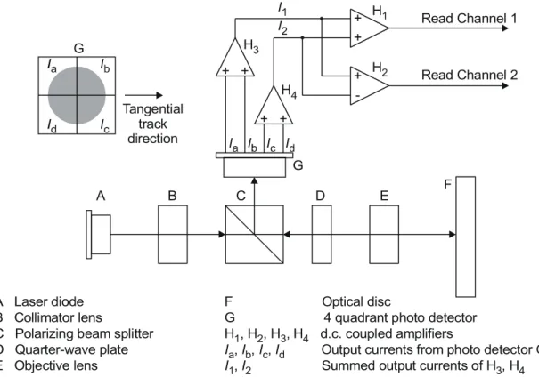
The basic set-up of the optical system of the Reference Drive used for measuring the write and read parameters is shown in Figure 2. Different components and locations of components are permitted, provided that the performance remains the same as that of the set-up in Figure 2. The optical system shall be such that the detected light reflected from the entrance surface of the disk is minimized so as not to influence the accuracy of the measurements.
+ + + -+ + + + Read Channel 2 Read Channel 1 H1 H4 H3 H2 A Laser diode B Collimator lens
C Polarizing beam splitter D Quarter-wave plate E Objective lens
B
A C D E F
F Optical disc
G 4 quadrant photo detector H H H H H H 1 2 3 4 a b c d 1 2 3 4 , , , d.c. coupled amplifiers
, , , Output currents from photo detector G , Summed output currents of ,
I I I I I I G G Tangential track direction
Figure 2 — Optical system of the Reference Drive
The combination of a polarizing beam splitter C and a quarter-wave plate D shall separate the entrance optical beam from the laser diode A and the reflected optical beam from the disk F. The beam splitter C shall have a p-s intensity reflectance ratio of at least 100.
9.2 Optical
beam
The focused optical beam used for writing and reading data shall have the following properties: a) Wavelength (λ) nm 5 nm 10 nm (see Annex K) 655 − +
b) Numerical aperture of the objective lens (NA) 0,65 ± 0,01
c) The objective lens shall be compensated for spherical aberrations caused by a parallel substrate with nominal thickness (0,6 mm) and nominal refractive index (1,55).
d) Wave front aberration 0,033 ×λ rms max.
e) Light intensity at the rim of the pupil of the 35 % to 50 % of the maximum intensity
objective lens in the radial direction and 45 % to 60 %
in the tangential direction.
f) Polarization of the light Circular
g) Read power (average) 0,7 mW ± 0,1 mW
(d.c. or HF modulated with a frequency >400 MHz)
h) Write power and pulse width see Annex G
i) Relative Intensity Noise (RIN)* of the laser diode -134 dB/Hz max. *RIN (dB/Hz) = 10 log [(a.c. light power density / Hz) / d.c. light power]
9.3
Read channel 1
Read channel 1 shall be provided to generate signals from the marks and spaces in the recording layer. This Read channel shall be used for reading the user-written information, using the change in reflectivity of the marks and spaces. The read amplifiers after the photo detectors in the Read channel shall have a flat response within 1 dB from d.c. to 20 MHz.
For measurement of jitter, the characteristics of the PLL and the slicer, etc. are specified in Annex E.
9.4 Disk
clamping
For measuring, the disk shall be clamped between two concentric rings covering most of the Clamping Zone (see 10.5). The top clamping area shall have the same diameters as the bottom clamping area (Figure 3).
disk dout din F1 F1 F2 α
Figure 3 — Clamping and chucking conditions Clamping shall occur between
mm 0,0 mm 0,5 in 22,3mm − + = d and mm 0,5 mm 0,0 out 32,7mm − + = d
The total clamping force shall be F1 = 2,0 N ± 0,5 N. In order to prevent warping of the disk under the moment of force generated by the clamping force and the chucking force F2 exerted on the rim of the centre hole of the disk, F2 shall not exceed 0,5 N (see Figure 3).
The tapered cone angle, α, shall be 40,0°± 0,5°.
9.5
Rotation of the disk
The actual rotation speed for reading the disk shall be such that it results in the Reference velocity of 3,49 m/s ± 0,03 m/s at the nominal Channel bit rate of 26,156 25 Mbit/s. The direction of rotation shall be counter-clockwise when viewed from the objective lens.
The actual rotation speed (vactual) for writing the disk shall be such that it includes all Primary
and Upper velocities for which parameters are specified in the Physical format information in the ADIP Aux Frames in the Lead-in Zone of the disk (see 14.4.1.1 and 14.4.2).
NOTE
The rotational speed of the disk is depending on the radial position: RPM
r v velocity angular × × =
π
2 60 actualWhen testing the disk the actual speed is limited such that the angular velocity does not exceed 10 000 RPM.
9.6
Wobble channel (Read channel 2)
Read channel 2 of the drive provides the wobble signals to control the access to addressed locations on the disk during writing. The wobble signal is generated in Read Channel 2 as a signal (I1 - I2) related to the difference in the amount of light in the two halves of the exit pupil of the objective lens. The read amplifiers after the photo detectors in the Read channel shall have a flat response within 1 dB from d.c. to 20 MHz.
9.7
Tracking channel (Read channel 2)
Read channel 2 of the drive provides the tracking error signals to control the servos for radial tracking of the optical beam. The radial tracking error is generated in Read Channel 2 as a signal (I1 - I2) related to the difference in the amount of light in the two halves of the exit pupil of the objective lens.
The method of generating the axial tracking error is not specified for the Reference Drive.
9.8
Reference servo systems
9 . 8 . 1 N o r m a l i z e d s e r vo t r a n s f e r f u n c t i o n
The open-loop transfer function, Hs(iω) for the axial and radial tracking servos is given by equation (1), 0 0 2 0 s 3 i 1 3i 1 i 3 1 ) (i H ω + ω + × ⎟⎠ ⎞ ⎜⎝ ⎛ ω × = ω ω ω ω (1) where: i= −1 , ω = 2π f and ω0 = 2π f0
and f0 is the 0 dB crossover frequency of the open-loop transfer function. The crossover frequencies of the lead-lag network of the servo are
lead break frequency: f1 = f0 / 3 lag break frequency: f2 = f0× 3
Another frequency of importance is the frequency fX at which a sinusoidal displacement with an amplitude equal to the maximum allowed residual tracking error emax, corresponds to the maximum expected acceleration αmax. This frequency can be calculated as follows:
max max X 21 e f α π =
Because the tracking error signals from the disk can have rather large variations, the tracking error signal fed into each reference servo loop shall be adjusted to a fixed level (effectively calibrating the total loop gain), such to guarantee the specified bandwidth.
9 . 8 . 2 R e f e r e n c e S e r vo f o r A x i a l T r a c k i n g
The crossover frequency of the normalized servo transfer function (Hs) for axial tracking, f0 = ω0 / (2π) shall be given by equation (2), where αmax is the maximum expected axial acceleration of 8,0 m/s2, which is multiplied by a factor m = 1,5 for servo margin. The tracking
error emax, caused by this m×αmax, shall be 0,20 μm. Thus the crossover frequency f0 shall be given by
6 max max 0 10 20 , 0 8 5 , 1 3 2 1 m 3 2 1 − × × × π = α × × π = e f = 2,1 kHz (2)
Bandwidth from 100 Hz to 10 kHz
⏐1+H⏐ shall be within 20 % of ⏐1+Hs⏐.
Bandwidth from 26 Hz to 100 Hz
| 1+H | shall be within the limits enclosed by the following four points. 1) 41,7 dB at 100 Hz (⏐1+Hs⏐ at 100 Hz – 20 %)
2) 45,2 dB at 100 Hz (⏐1+Hs⏐ at 100 Hz + 20 %) 3) 65,1 dB at 26 Hz (⏐1+Hs⏐ at 26 Hz – 20 %)
4) 85,1 dB at 26 Hz (⏐1+Hs⏐ at 26 Hz – 20 % + 20 dB)
Bandwidth from 9,5 Hz to 26 Hz
⏐1+H⏐ shall be between 65,1 dB and 85,1 dB.
Gain (dB) 85,1 80 65,1 60 45,2 41,7 20 0 1 9,5 26 100 1000 10000 100000 Frequency (Hz) -10
Figure 4 — Reference servo for axial tracking 9 . 8 . 3 R e f e r e n c e S e r vo f o r R a d i a l T r a c k i n g
The crossover frequency of the normalized servo transfer function (Hs) for radial tracking, f0 = ω0 / (2π) shall be given by equation (3), where αmax is the maximum expected radial acceleration of 1,1 m/s2, which is multiplied by a factor m = 1,5 for servo margin. The tracking error emax, caused by this m×αmax, shall be 0,022 μm.
Thus the crossover frequency f0 shall be given by
6 max max 0 10 022 , 0 1 , 1 5 , 1 3 2 1 m 3 2 1 − × × × π = α × × π = e f = 2,4 kHz (3)
For an open loop transfer function H of the Reference Servo for radial tracking, ⏐1+H⏐ is limited as schematically shown by the shaded region of Figure 5.
Bandwidth from 100 Hz to 10 kHz
⏐1+H⏐ shall be within 20 % of⏐1+Hs⏐.
Bandwidth from 28,2 Hz to 100 Hz
⏐1+H⏐ shall be within the limits enclosed by the following four points. 1) 43,7 dB at 100 Hz (⏐1+Hs⏐ at 100 Hz – 20 %)
2) 47,2 dB at 100 Hz (⏐1+Hs⏐ at 100 Hz + 20 %) 3) 65,6 dB at 28,2 Hz (⏐1+Hs⏐ at 28,2 Hz – 20 %)
4) 85,6 dB at 28,2 Hz (⏐1+Hs⏐ at 28,2 Hz – 20 % + 20 dB)
Bandwidth from 9,5 Hz to 28,2 Hz
⏐1+H⏐ shall be between 65,6 dB and 85,6 dB.
Gain (dB) 85,6 80 65,6 60 47,2 43,7 20 0 1 9,5 28,2 100 1000 10000 100000 Frequency (Hz) -10
Section 2 — Dimensional, mechanical and physical characteristics
of the disk
10 Dimensional
characteristics
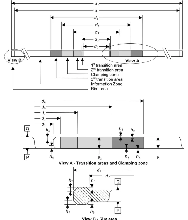
Dimensional characteristics are specified for those parameters deemed mandatory for interchange and compatible use of the disk. Where there is freedom of design, only the functional characteristics of the elements described are indicated. The enclosed drawing, Figure 6 shows the dimensional requirements in summarized form. The different parts of the disk are described from the centre hole to the outside rim.
d3 d4 d5 d6 d2 e2 h3 h4 e1 h2 h1
View A - Transition areas and Clamping zone
d3 d4 d5 d6 d2 1st transition area 2nd transition area Clamping zone 3rd transition area Information Zone Rim area d1 View A d7 h6 h7 h7 h6 d1 d7 h5 h5
View B - Rim area View B
Q
Q P
P
10.1 Reference
Planes
The dimensions are referred to two Reference Planes P and Q.
Reference Plane P is the primary Reference Plane. It is the plane on which the bottom surface of the Clamping Zone rests (see 10.5).
Reference Plane Q is the plane parallel to Reference Plane P at the height of the top surface of the Clamping Zone (see Figure 6).
10.2 Overall
dimensions
The disk shall have an overall diameter (for 80 mm disk see Annex A)
d1 = 120,00 mm ± 0,30 mm
The centre hole of a substrate or a dummy substrate shall have a diameter (see Figure 7).
mm 0,00 mm 0,15 substrate 15,00mm − + = d
The hole of an assembled disk, i.e. with bothparts bonded together, shall have a diameter
d2 = 15,00 mm min.
dsubstrate
dsubstrate d2
Figure 7 — Hole diameters for an assembled disk
The corners of the centre hole shall be free of any burrs or sharp features and shall be rounded off or chamfered by
h5 = 0,1 mm max.
The thickness of the disk shall be
mm 0,06 mm 0,30 1 1,20mm− + = e
10.3 First transition area
In the area defined by d2 andd3 = 16,0 mm min.
the surface of the disk is permitted to be above Reference Plane P and/or below Reference Plane Q by 0,10 mm max.
10.4 Second transition area
This area shall extend between diameter d3 and diameter d4 = 22,0 mm max.
In this area the disk may have an uneven surface or burrs up to 0,05 mm max. beyond Reference Planes P and/or Q.
10.5 Clamping
Zone
This Zone shall extend between diameter d4 and diameter d5 = 33,0 mm min.
Each side of the Clamping Zone shall be flat within 0,1 mm. The top side of the Clamping Zone, i.e. that of Reference Plane Q shall be parallel to the bottom side, i.e. that of Reference Plane P within 0,1 mm.
In the Clamping Zone the thickness e2 of the disk shall be mm 0,10 mm 0,20 2 1,20mm − + = e
10.6 Third transition area
This area shall extend between diameter d5 and diameter d6 = 44,0 mm max.
In this area the top surface is permitted to be above Reference Plane Q by
h1 = 0,25 mm max. or below Reference Plane Q by
h2 = 0,10 mm max.
The bottom surface is permitted to be above Reference Plane P by
h3 = 0,10 mm max. or below Reference Plane P by
h4 = 0,25 mm max.
10.7 Information
Zone
The Information Zone shall extend from diameter d6 to diameter (for 80 mm disk see Annex A) d7 = 117,5 mm min.
This Zone consists of the Lead-in Zone, the Data Zone, the Lead-out Zone and the Inner and Outer Drive Areas (see also Clause 15).
10.8 Rim
Area
The rim area is that area extending from diameter d7 to diameter d1. In this area the surfaces are permitted to both extend beyond Reference Plane Q or Reference Plane P
h6 = 0,1 mm max.
The outer corners of the disk shall be free of any burrs or sharp features and shall be rounded off or chamfered by
10.9 Remark on tolerances
All heights specified in the preceding clauses and indicated by hi are independent from each
other. This means that, for example, if the top surface of the third transition area is below Reference Plane Q by up to h2, there is no implication that the bottom surface of this area has to be above Reference Plane P by up to h3. Where dimensions have the same - generally maximum - numerical value, this does not imply that the actual values have to be identical.
11 Mechanical
characteristics
11.1 Mass
The mass of the disk shall be in the range of 13,0 g to 20,0 g (for 80 mm disk see Annex A).
11.2 Moment of inertia
The moment of inertia of the disk, relative to its rotation axis, shall not exceed 0,040 g⋅m2 (for 80 mm disk see Annex A).
11.3 Dynamic
imbalance
The dynamic imbalance of the disk, relative to its rotation axis, shall not exceed 2,5 g⋅mm (for 80 mm disk see Annex A).
11.4 Axial
runout
When measured by the optical system with the Reference Servo for axial tracking, the disk rotating at the Reference velocity of 3,49 m/s (see 9.5), the deviation of the recording layer from its nominal position in the direction normal to the Reference Planes shall not exceed 0,30 mm. Some explanation about the use of the Reference Servo as a measurement tool and the way to translate the measurement results to a practical implementation for a high-speed servo is given in Annex L.
1 1 . 4 . 1 T r a c k i n g r e q u i r e m e n t s a t t h e R e f e r e n c e ve l o c i t y ( C L V )
The residual tracking error below 10 kHz, measured on the blank disk using the Reference Servo for axial tracking and the disk rotating at the Reference velocity, shall not exceed 0,13 μm (displacement of the objective lens needed to move the focal point of the optical beam onto the recording layer).
The measuring filter shall be a Butterworth LPF, fc (-3 dB): 10 kHz, with slope : -80 dB/decade.
1 1 . 4 . 2 T r a c k i n g r e q u i r e m e n t s a t 3 0 0 0 R P M ( C A V )
Disks suited to be recorded at speeds > 4× the Reference velocity, shall also fulfill the following requirement:
the residual tracking error below 10 kHz, measured on the blank disk using the Reference Servo for axial tracking and the disk rotating at a fixed rotational speed of 3 000 RPM, shall not exceed Eax(r) μm, where Eax is a function of the radius r according to the following specifications: for r≤ 29 mm: Eax(r) = 0,20 μm, for r≥ 29 mm: 0,20 29 ) ( E 2 ax ⎟ × ⎠ ⎞ ⎜ ⎝ ⎛ = r r μm, with r expressed in mm.
Disks suited to be recorded at speeds > 8 × the Reference velocity, shall furthermore fulfil the following requirement, additional to the requirement above:
If present, the 50 Hz component shall be removed from the residual tracking error before applying these requirements (e.g. by software processing of the sampled measurement data).
11.5 Radial
runout
The runout of the outer edge of the disk shall not exceed 0,30 mm peak-to-peak. The radial runout of tracks shall not exceed 70 μm peak-to-peak.
Some explanation about the use of the Reference Servo as a measurement tool and the way to translate the measurement results to a practical implementation for a high-speed servo is given in Annex L.
1 1 . 5 . 1 T r a c k i n g r e q u i r e m e n t s a t t h e R e f e r e n c e ve l o c i t y ( C L V )
The residual tracking error below 1,1 kHz (= ƒX as defined in 9.8.1), measured on the blank disk using the Reference Servo for radial tracking and the disk rotating at the Reference velocity of 3,49 m/s (see 9.5), shall not exceed 0,015 μm.
The measuring filter shall be a Butterworth LPF, fc (-3 dB) : 1,1 kHz, with slope : -80 dB/decade.
The rms noise value of the residual error signal in the frequency band from 1,1 kHz to 10 kHz, measured with an integration time of 20 ms, using the Reference Servo for radial tracking, shall not exceed 0,016 μm.
The measuring filter shall be a Butterworth BPF,
frequency range (-3 dB) : 1,1 kHz, with slope : +80 dB/decade to : 10 kHz, with slope : -80 dB/decade.
1 1 . 5 . 2 T r a c k i n g r e q u i r e m e n t s a t 3 0 0 0 R P M ( C A V )
Disks suited to be recorded at speeds > 4× the Reference velocity, shall also fulfill the following requirement:
the residual tracking error below 10 kHz, measured on the blank disk using the Reference Servo for radial tracking and the disk rotating at a fixed rotational speed of 3 000 RPM, shall not exceed Erad(r) μm, where Erad is a function of the radius r according to the following specifications: for r≤ 29 mm: Erad(r) = 0,025 μm, for r≥ 29 mm: 0,025 29 ) ( E 2 rad ⎟ × ⎠ ⎞ ⎜ ⎝ ⎛ = r r μm, with r expressed in mm.
Disks suited to be recorded at speeds > 8 × the Reference velocity, shall furthermore fulfil the following requirement, additional to the requirement above:
the residual tracking error shall not exceed 0,055 μm at any radius.
If present, the 50 Hz component shall be removed from the residual tracking error before applying these requirements (e.g. by software processing of the sampled measurement data). This process effectively removes the influence of the pure eccentricity of the disk.
12 Optical characteristics in the Information Zone
12.1 Index of refraction
The index of refraction of the substrate in the Information Zone shall be 1,55 ± 0,10.
12.2 Thickness of the substrate
The thickness of the substrate, from the entrance surface to the recording layer, varies with the index of refraction of the substrate and shall be defined as the enclosed region in Figure 8.
1,40 1,50 1,60 1,70 0,600 0,580 0,620 (1,45; 0,633) (1,56; 0,620) (1,65; 0,620) (1,45; 0,593) (1,56; 0,580) (1,65; 0,580) Thickness (mm) Index of refraction
Figure 8 — Thickness of the substrate
12.3 Reflectivity
The double-pass optical transmission of the substrate and the reflectivity of the recording layer are measured together as the reflectance R of the disk. When measured according to Annex C the value of R shall be
in the Information Zone 0,45 ≤Rd≤ 0,85 in the unrecorded groove 0,45 ≤R14H≤ 0,85 in the recorded groove
The product of the reflectance of the unrecorded groove Rd and the optimized write power Ppeak for the write strategy concerned (see 29.3.2) shall fulfil the following requirement:
Rd× actual Ppeak ≤ strategy e basic writ for for peak_max concerned strategy write for for peak_max IND IND λ ≤ λ λ ≤ λ P P × 9 mW
12.4 Birefringence
12.5 Angular
deviation
The angular deviation is the angle α between a parallel incident beam perpendicular to the Reference Plane P and the reflected beam (see Figure 9). The incident beam shall have a diameter in the range 0,30 mm to 3,0 mm. This angle α includes deflection due to the entrance surface and to the unparallelism of the recording layer with the entrance surface.
α Incident beam Reflected beam Entrance surface Substrate Recording layer P
Figure 9 — Angular deviation α The angular deviation shall be
In radial direction : |α| = 0,70° max.
The variation of α in radial direction over one revolution shall be 0,80° peak-to-peak max. In tangential direction : |α| = 0,30° max.
Section 3 — Format of information
13 Data
format
The data received from the host, called Main Data, is formatted in a number of steps before being recorded on the disk.
It is transformed successively into − a Data Frame, − a Scrambled Frame, − an ECC Block, − 16 Recording Frames, − 16 Physical Sectors, − a Recording Unit.
These steps are specified in the following clauses.
13.1 Data
Frames
A Data Frame shall consist of 2 064 bytes arranged in an array of 12 rows each containing 172 bytes (Figure 10). The first row shall start with three fields, called Identification Data (ID), ID Error Detection Code (IED), and RSV bytes, followed by 160 Main Data bytes. The next 10 rows shall each contain 172 Main Data bytes, and the last row shall contain 168 Main Data bytes followed by four bytes for recording an Error Detection Code (EDC). The 2 048 Main Data bytes are identified as D0 to D2 047. ←⎯⎯⎯⎯⎯⎯⎯⎯⎯⎯⎯⎯⎯ 172 bytes ⎯⎯⎯⎯⎯⎯⎯⎯⎯⎯⎯⎯⎯→ 4 bytes 2 bytes 6 bytyes ↑ ⏐ ⏐ ⏐ ⏐ ⏐ ⏐ ⏐ ⏐
ID IED RSV Main data 160 bytes (D0 - D159) Main data 172 bytes (D160 - D331)
Main data 172 bytes (D332 - D503) Main data 172 bytes (D504 - D675) Main data 172 bytes (D676 - D847) Main data 172 bytes (D848 - D1 019) 12 rows Main data 172 bytes (D1 020 - D1 191)
⏐ ⏐ ⏐ ⏐ ⏐ ⏐ ⏐ ↓
Main data 172 bytes (D1 192 - D1 363) Main data 172 bytes (D1 364 - D1 535) Main data 172 bytes (D1 536 - D1 707) Main data 172 bytes (D1 708 - D1 879)
Main data 168 bytes (D1 880 - D2 047) EDC
4
bytes Figure 10 — Data Frame
1 3 . 1 . 1 I d e n t i f i c a t i o n D a t a ( I D )
This field shall consist of four bytes, the bits of which are numbered consecutively from b0 (lsb) to b31 (msb), see Figure 11.
Sector Information Physical Sector Number
(msb) b31 b24 b23 b0 (lsb) b31 b30 b29 b28 b27 b26 b25 b24 Sector format type Tracking method
Reflectivity Reserved Zone type
Data type
Layer number Figure 11 — Identification Data (ID)
The bits of the most significant byte, the Sector Information, shall be set as follows: Bit b31 shall be set to ZERO, indicating a CLD format
Bit b30 shall be set to ZERO, indicating pit tracking capability (see 31.2.5) Bit b29 shall be set to ZERO indicating that the reflectance is greater than 40 % Bit b28 shall be set to ZERO
Bits b27 to b26 shall be set to
ZERO ZERO in the Data Zone ZERO ONE in the Lead-in Zone ONE ZERO in the Lead-out Zone
Bit b25 shall be set to ZERO, indicating read only data.
Bit b24 shall be set to ZERO, indicating that through an entrance surface only one recording layer can be accessed.
The least significant three bytes, bits b23 to b0, shall specify the Physical Sector Number in binary notation. The Physical Sector Number of the first Physical Sector of an ECC Block shall be an integer multiple of 16.
1 3 . 1 . 2 I D E r r o r D e t e c t i o n C o d e ( I E D )
When identifying all bytes of the array shown in Figure 10 as Ci,j for i = 0 to 11 and j = 0 to 171,
the bytes of IED are represented by C0,j for j = 4 to 5. Their setting is obtained as follows.
) ( G mod ) I( C ) IED( 5 2 E 5 4 0, x x x x x j j j = = − =
∑
where and GE(x) = (x + 1)(x + α) j j j x x − =∑
= 3 3 0 0, C ) I(α is the primitive root of the primitive polynomial P(x) = x 8 + x 4 + x 3 + x 2 + 1
1 3 . 1 . 3 R S V
This field shall consist of 6 bytes. The first byte may be set by the application. If not specified by the application, it is reserved and shall be set to (00). The remaining 5 bytes are reserved and shall all be set to (00).
Under no circumstance may other data received from the host be recorded in this field.
Circumvention: Recorders and recording drives shall be considered as circumvention devices
when these are produced to record, or can easily be modified to record, in any manner, a user−defined number in this field.
1 3 . 1 . 4 E r r o r D e t e c t i o n C o d e ( E D C )
This 4-byte field shall contain the parities of an Error Detection Code computed over the preceding 2 060 bytes of the Data Frame. Considering the Data Frame as a single bit field starting with the most significant bit of the first byte of the ID field and ending with the least significant bit of the EDC field, then this msb will be b16 511 and the lsb will be b0. Each bit bi of the EDC is shown as follows for i = 0 to 31:
) G( mod ) I( b ) EDC( 31 0 x x x x i i i = =
∑
= where and G(x) = x 32 + x 31 + x 4 + 1 i i i x x∑
= =16511 32 b ) (I13.2 Scrambled
Frames
The 2 048 Main Data bytes shall be scrambled by means of the circuit shown in Figure 12 which shall consist of a feedback bit shift register in which bits r7 (msb) to r0 (lsb) represent a scrambling byte at each 8-bit shift.
r14 r13 r12 r11 r10 r9 r8 r7 r6 r5 r4 r3 r2 r1 r0
S at each 8-bit shiftk
Figure 12 — Feedback shift register
At the beginning of the scrambling procedure of a Data Frame, positions r14 to r0 shall be pre-set to the value(s) specified in Table 1 (the msb of the pre-set value shall be discarded). The same pre-set value shall be used for 16 consecutive Data Frames. After 16 groups of 16 Data Frames, the sequence is repeated. The initial pre-set number is equal to the value represented by bits b7 (msb) to b4 (lsb) of the ID field of the Data Frame. Table 1 specifies the initial pre-set value of the shift register corresponding to the 16 initial pre-set numbers.
Table 1 — Initial values of the shift register
Initial pre-set number Initial pre-set value Initial pre-set number Initial pre-set value (0) (0001) (8) (0010) (1) (5500) (9) (5000) (2) (0002) (A) (0020) (3) (2A00) (B) (2001) (4) (0004) (C) (0040) (5) (5400) (D) (4002) (6) (0008) (E) (0080) (7) (2800) (F) (0005)
The part of the initial value of r7 to r0 is taken out as scrambling byte S0. After that, an 8-bit shift is repeated 2 047 times and the following 2 047 bytes shall be taken from r7 to r0 as scrambling bytes S1 to S2 047. The Main Data bytes Dk of the Data Frame become scrambled bytes D’k where D’k = Dk⊕ Sk for k = 0 to 2 047 (⊕ stands for Exclusive OR)
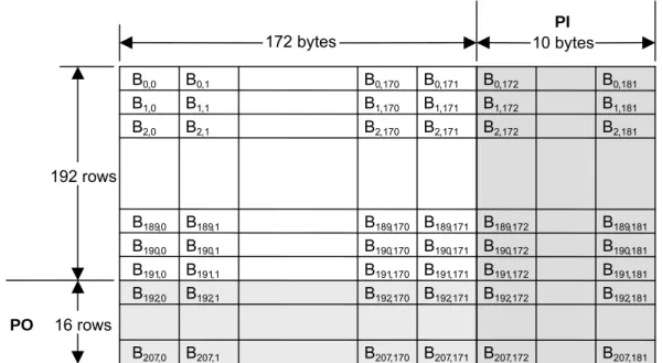
13.3 ECC
Blocks
An ECC Block is formed by arranging 16 consecutive Scrambled Frames in an array of 192 rows of 172 bytes each (Figure 13). To each of the 172 columns 16 bytes of Parity of Outer Code are added, then, to each of the resulting 208 rows, 10 bytes of Parity of Inner Code are added. Thus a complete ECC Block comprises 208 rows of 182 bytes each. The bytes of this array are identified as Bi,jas follows, where i is the row number and j is the column number.
Bi,jfor i = 0 to 191 and j = 0 to 171 are bytes from the Scrambled Frames Bi,j for i = 192 to 207 and j = 0 to 171 are bytes of the Parity of Outer Code Bi,j for i = 0 to 207 and j = 172 to 181 are bytes of the Parity of Inner Code
192 rows B0,0 B1,0 B2,0 B0,1 B0,170 B0,171 B0,172 B0,181 B1,1 B1,170 B1,171 B1,172 B1,181 B2,1 B2,170 B2,171 B2,172 B2,181 B190,0 B190,1 B190,170 B190,171 B190,172 B190,181 B189,0 B189,1 B189,170 B189,171 B189,172 B189,181 B207,0 B207,1 B207,170 B207,171 B207,172 B207,181 B191,0 B191,1 B191,170 B191,171 B191,172 B191,181 B192,0 B192,1 B192,170 B192,171 B192,172 B192,181 16 rows 10 bytes PI 172 bytes PO
Figure 13 — ECC Block The PO and PI bytes shall be obtained as follows.
In each of columns j = 0 to 171, the 16 PO bytes are defined by the remainder polynomial Rj(x) to form the outer code RS(208,192,17).
) ( G mod ) ( I B ) ( R 207- 16 PO 207 192 x x x x x i j i i,j j =
∑
= = where and i i i,j j x x191 -191 0 B ) ( I∑
= = =∏
15 +α 0 = PO( ) ( ) G k k x xIn each of rows i = 0 to 207, the 10 PI bytes are defined by the remainder polynomial Ri(x) to form
the inner code RS(182,172,11).
) ( G mod ) ( I B ) ( R 181- 10 PI 181 172 x x x x x j i j i,j i =
∑
= = where and j j i,j i x x171 -171 0 B ) ( I∑
= = =∏
9 +α 0 = PI( ) ( ) G k k x x13.4 Recording
Frames
Sixteen Recording Frames shall be obtained by interleaving one of the 16 PO rows at a time after every 12 rows of an ECC Block (Figure 14). This is achieved by re-locating the bytes Bi,j of the
ECC Block as Bm,n for
m = i + int [i / 12] and n = j for i≤ 191
m = 13 × (i - 191) - 1 and n = j for i≥ 192
where int [x] represents the largest integer not greater than x.
Thus the 37 856 bytes of an ECC Block are re-arranged into 16 Recording Frames of 2 366 bytes. Each Recording Frame consists of an array of 13 rows of 182 bytes.
182 bytes 13 rows B0,0 B11,0 B12,0 B23,0 B192,0 B193,0 B191,0 B207,0 B180,0 B0,171 B11,171 B192,171 B193,171 B191,171 B207,171 B180,171 B12,171 B23,171 B0,172 B11,172 B192,172 B193,172 B191,172 B207,172 B180,172 B12,172 B23,172 B0,181 B11,181 B192,181 B193,181 B191,181 B207,181 B180,181 B12,181 B23,181 13 rows 13 rows Recording Frames 2 - 14 Recording Frame 0 Recording Frame 1 Recording Frame 15
. . . .
. . . .
. . . .
. . . .
. . . .
. . . .
. . . .
. . . .
. . . .
. . .
. . .
. . .
. . .
. . .
. . .
. . .
. . .
. . .
Figure 14 — Recording Frames obtained from an ECC Block
13.5 Modulation and NRZI conversion
The 8-bit bytes of each Recording Frame shall be transformed into 16-bit Code Words with the run length limitation that between 2 ONEs there shall be at least 2 ZEROs and at most 10 ZEROs (RLL(2,10)). Annex H specifies the conversion tables to be applied. The Main Conversion table and the Substitution table specify a 16-bit Code Word for each 256 8-bit bytes with one of 4 States. For each 8-bit byte, the tables indicate the corresponding Code Word, as well as the State for the next 8-bit byte to be encoded.
The 16-bit Code Words shall be NRZI-converted into Channel bits before recording on the disk (see Figure 15). The Channel clock period is the time between 2 consecutive Channel bits.
16-bit Code Words 8-bit bytes NRZ conversion modulator Exclusive-OR 1 T delay 16 channel bits NRZI converted pulses
T = 1 channel clock period
16-bit Code Word pattern: 0 1 0 0 1 0 0 0 1 0 0 0 0 1 0 0 NRZ converted signal:
NRZI converted pulses:
Figure 15 — NRZI conversion
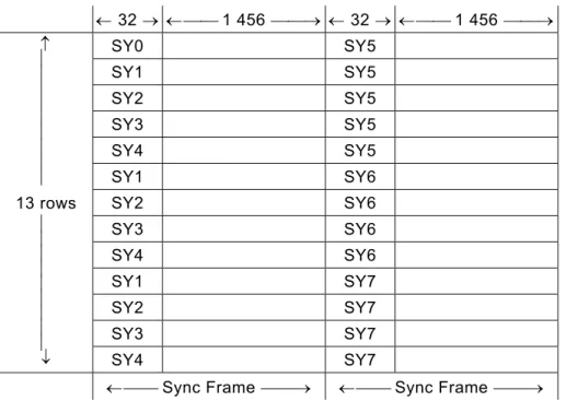
13.6 Physical
Sectors
The structure of a Physical Sector is shown in Figure 16. It shall consist of 13 rows, each comprising two Sync Frames. A Sync Frame shall consist of a SYNC Code from Table 2 and 1 456 Channel bits representing 91 8-bit bytes. Each row of the Physical Sector shall consist of two Sync Frames with the first 1 456 Channel bits representing the first 91 bytes of each row of a Recording Frame and the second 1 456 Channel bits representing the second 91 bytes of each row of a Recording Frame.
← 32 → ←⎯⎯ 1 456 ⎯⎯→ ← 32 → ←⎯⎯ 1 456 ⎯⎯→ ↑ ⏐ ⏐ ⏐ ⏐ ⏐ ⏐ ⏐ ⏐ ⏐ 13 rows ⏐ ⏐ ⏐ ⏐ ⏐ ⏐ ⏐ ⏐ ⏐ ↓ SY0 SY5 SY1 SY5 SY2 SY5 SY3 SY5 SY4 SY5 SY1 SY6 SY2 SY6 SY3 SY6 SY4 SY6 SY1 SY7 SY2 SY7 SY3 SY7 SY4 SY7 ←⎯⎯ Sync Frame ⎯⎯→ ←⎯⎯ Sync Frame ⎯⎯→
Figure 16 — Physical Sector
Recording of the Physical Sector shall start with the first Sync Frame of the first row, followed by the second Sync Frame of that row, and so on, row-by-row. The state of each SYNC Code and each subsequent set of 16 Channel bits shall follow the rules defined in 13.8.
Table 2 — SYNC Codes State 1 and State 2 (next state is state 1)
Primary SYNC codes Secondary SYNC codes
(msb) (lsb) (msb) (lsb) SY0 = 0001001001000100 0000000000010001 / 0001001000000100 0000000000010001 SY1 = 0000010000000100 0000000000010001 / 0000010001000100 0000000000010001 SY2 = 0001000000000100 0000000000010001 / 0001000001000100 0000000000010001 SY3 = 0000100000000100 0000000000010001 / 0000100001000100 0000000000010001 SY4 = 0010000000000100 0000000000010001 / 0010000001000100 0000000000010001 SY5 = 0010001001000100 0000000000010001 / 0010001000000100 0000000000010001 SY6 = 0010010010000100 0000000000010001 / 0010000010000100 0000000000010001 SY7 = 0010010001000100 0000000000010001 / 0010010000000100 0000000000010001
State 3 and State 4 (next state is state 1)
Primary SYNC codes Secondary SYNC codes
(msb) (lsb) (msb) (lsb) SY0 = 1001001000000100 0000000000010001 / 1001001001000100 0000000000010001 SY1 = 1000010001000100 0000000000010001 / 1000010000000100 0000000000010001 SY2 = 1001000001000100 0000000000010001 / 1001000000000100 0000000000010001 SY3 = 1000001001000100 0000000000010001 / 1000001000000100 0000000000010001 SY4 = 1000100001000100 0000000000010001 / 1000100000000100 0000000000010001 SY5 = 1000100100000100 0000000000010001 / 1000000100000100 0000000000010001 SY6 = 1001000010000100 0000000000010001 / 1000000001000100 0000000000010001 SY7 = 1000100010000100 0000000000010001 / 1000000010000100 0000000000010001
13.7 Layout of a Recording UNit (RUN)
A RUN shall consist of an integer number (M ≥ 1) of sets of 16 Physical Sectors, each from a single ECC Block. The M ECC Blocks shall be preceded by 8 Channel bits, which are meant to reduce possible influences of inaccuracies of the linking point, while the last 8 Channel bits of the last Physical Sector shall be discarded at recording. The 8 linking Channel bits and the next SYNC Code SY0 (chosen from State 1/2 or State 3/4) shall be chosen randomly, such that the runlength constraints specified in 13.5 are fulfilled.
Each RUN of M ECC Blocks (M≥ 1) starting with ECC Block N shall be recorded in the following way:
8 Channel bits for linking in ECC Block N-1, full ECC Blocks N to N + M – 2 (if M≥ 2),
ECC Block N + M− 1, except for the last 8 Channel bits, which bits shall not be recorded. The positioning of a Recording Unit is shown in Figure 17.
When the RUN starting with ECC Block N is to be recorded, and ECC Block N-1 has not yet been recorded, then the RUN shall be extended with a dummy ECC Block N-1 of which all Main Data bytes shall be set to (00) (see also Clause 23: Sequential recording).
8 T
±5 T max
theoretical start position
actual start position
middle of wobble 15 8 Channel bits ECC Block N ECC Block + -1N M last 8 Channel bits MECC Blocks to be discarded at recording to be recorded linking
Figure 17 — Recording Unit
1 3 . 7 . 1 R e c o r d i n g U n i t p o s i t i o n
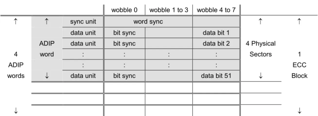
Each ECC Block, consisting of 16 Physical Sectors, shall correspond to 4 ADIP words (see 14.4.1.1). RUNs shall be mapped onto the structure of tracks (see 14.4), such that the Physical Sector Numbers (PSN), of which the 2 least significant bits have been discarded, correspond to the local Physical Address in ADIP (PAA). In mathematical form: PSN = 4×PAA + i, where
i = 0, 1, 2, or 3 (for example: Physical Sector Numbers (030000) to (030003) correspond to Physical ADIP Address (00C000)).
The reference for the theoretical start positions is wobble 15 following the ADIP word sync unit of the ADIP words of which the 2 least significant address bits are 00 (see 14.4.1.1 and Figure 21). The theoretical start position is 8 Channel bits after the nominal position of the zero crossing in the middle of the above mentioned wobble 15 of the wobble signal from Read channel 2.
The start of each recording shall be within ± 5 Channel bits of the theoretical start position. During writing the Channel bit clock shall be phase locked to the wobble frequency.
13.8 d.c. component suppression control
To ensure a reliable radial tracking and a reliable detection of the HF signals, the low frequency content of the stream of Channel bit patterns should be kept as low as possible. In order to achieve this, the Digital Sum Value (DSV, see 4.3) shall be kept as close to zero as possible. At the beginning of the modulation, the DSV shall be set to 0.
The different ways of diminishing the current value of the DSV are as follows: a) Choice of SYNC Codes between Primary or Secondary SYNC Codes.
b) For the 8-bit bytes in the range 0 to 87, the Substitution table offers an alternative 16-bit Code Word for all States.
c) For the 8-bit bytes in the range 88 to 255, when the prescribed State is 1 or 4, then the 16-bit Code Word can be chosen either from State 1 or from State 4, so as to ensure that the RLL requirement is met.
In order to use these possibilities, two data streams, Stream 1 and Stream 2, are generated. Stream 1 shall start with the Primary SYNC Code and Stream 2 with the Secondary SYNC Code of the same category of SYNC Codes. As both streams are modulated individually, they generate a different DSV because of the difference between the bit patterns of the Primary and Secondary SYNC Codes.