A PROPOSED UNIFIED VISUAL PROGRAMMING
LANGUAGE
By
NABOU DIENG
Bachelor of Science in Computer Science
Oklahoma State University
Stillwater, Oklahoma
2005
Submitted to the Faculty of the
Graduate College of the
Oklahoma State University
in partial fulfillment of
the requirements for
the Degree of
MASTER OF SCIENCE
ii
A PROPOSED UNIFIED VISUAL
PROGRAMMING LANGUAGE
Thesis Approved:
Dr. Blayne Mayfield
Thesis Adviser
Dr. John Chandler
Dr. Johnson Thomas
Dr. Mark Payton
iv
ACKNOWLEDGMENTS
The successful preparation of this research would not have been possible without the invaluable contribution of my adviser, Dr Blayne Mayfield, nor would it have been possible without the great educational experience received from the professors of the Computer Science department of Oklahoma State University. For these reasons I would like to express my deepest gratitude to the members of my committee: Dr Blayne Mayfield, Dr John Chandler and Dr Johnson Thomas. I also would like to extend my sincere thanks to Dr Mansur
Samadzadeh and Dr Nohpill Park, who have helped me tremendously during my university curriculum.
I further would like to thank my mother Dr Khadijhatou Seck for her unconditional encouragements in my studies, my dear brother Ababacar Dieng for his absolute support and my brother Madior Dieng for always motivating me.
Last but not least, I would like to take this opportunity to acknowledge the support and understanding throughout my life of my late farther Dr Papa Amath Dieng, who is not going to read these lines but who would have been proud to see me reach this milestone.
5
Table of Contents
Chapter
Page
LIST OF FIGURES ... 7
LIST OF TABLES ... 9
Chapter I ... 10
INTRODUCTION ... 10
1.1
Visual Programming Languages ... 10
1.2
Issues of Visual Programming Languages ... 11
1.3
Objectives and limits of this research ... 12
1.4
The Approach ... 12
1.5
Chapters overview ... 12
Chapter II ... 14
REVIEW OF LITERATURE ... 14
2.1
Background of VPLs... 14
2.2
VPL Classification System ... 16
2.3
VPL Grammar ... 17
2.4
Cognitive Dimension of VPLs ... 20
2.5
Short VPL Survey ... 21
2.6
Scaling up Visual Programming Languages ... 24
2.7
Iteration constructs in VPLs ... 26
2.8
Arrays representation in VPLs ... 28
2.9
Principles of programming languages ... 30
Chapter III ... 32
METHODOLOGY ... 32
3.1
VPLs Selection Process ... 32
3.2
Analysis of principles for the selected VPLs ... 34
3.3
Variables and literals ... 36
3.4
Arithmetic, Boolean, and Comparison Operations ... 42
3.5
Control Flow ... 47
3.6
Input / Output ... 55
6
3.7.1
UVPL Programming Features ... 63
3.7.2
UVPL Programming Constructs ... 71
3.7.3
Object-Oriented UVPL ... 77
3.7.4
Principles analysis of UVPL ... 81
Chapter IV ... 86
TESTING ... 86
4.1
Program Tests ... 86
4.1.1
Program Test in Alice 2.2 ... 89
4.1.2
Program Test in Lumina Analytica 4.2 ... 90
4.1.3
Program Test in Microsoft VPL 2.1 ... 91
4.1.4
Program Test in Tersus 1.3 ... 92
4.1.5
Program Test in UVPL ... 93
4.1.6
Analysis of the Program Tests ... 94
4.1.7
VPL Metrics for the Test Programs ... 95
4.1.8
Test Programs Counts ... 98
4.1.9
VPL Metrics Values for the Test Programs ... 99
Chapter V ... 103
CONCLUSION ... 103
5.1
Findings ... 103
5.2
Goals achieved ... 106
5.3
Halstead measurements ... 107
5.4
Future works ... 107
REFERENCES ... 109
APPPENDICES ... 110
Appendix A: Program test in Alice ... 110
Appendix B: Program test in MS VPL ... 119
Appendix C: Program test in Tersus ... 126
Appendix D: Program test in Analytica ... 134
Appendix E: Program test in UVPL ... 140
7
LIST OF FIGURES
Figure 2.2.1: Example of adding VPLs to the ACM CR system. Modified from figure 2.2.2 ...16
Figure 2.2.2: VPLs Classification system [3] ...17
Figure 2.5.1: static VIPR representation of an if statement [8]. ...22
Figure 2.8.1 Array of 2 dimensions with scroll bars [14] ...28
Figure 2.8.2: Summing a list in Formulate [14] ...29
Figure 3.2.1: Example of a variable in Alice ...39
Figure 3.2.2: Syntactic consistency violation ...39
Figure 3.2.3: Example of a variable with a long name ...39
Figure 3.2.4: example of a variable in Analytica ...40
Figure 3.2.5: some grokens and viprocons in Analytica ...40
Figure 3.2.6: Example of a variable in MS VPL ...41
Figure 3.2.7: example of a variable in Tersus ...42
Figure 3.2.8: addition in Alice ...45
Figure 3.2.9: comparison in Alice ...45
Figure 3.2.10: Example of Operation in Analytica ...46
Figure 3.2.11: invalid operation in MS VPL ...46
Figure 3.2.12: Invalid operation in Tersus ...47
Figure 3.2.13: While loop in Alice ...50
Figure 3.2.14: For loop in Alice ...50
Figure 3.2.15: Special library in Analytica ...51
Figure 3.2.16: Indirectness in Analytica. ...52
Figure 3.2.17: If viprocon in MS VPL ...53
Figure 3.2.18: Switch in MS VPL ...53
Figure 3.2.19: Control flow in Tersus ...54
Figure 3.2.20: Setting up input in Alice ...58
Figure 3.2.21: Setting up input in Analytica ...58
Figure 3.2.22: Input in Analytica...59
Figure 3.2.23: Output and Input example in MS VPL ...60
Figure 3.2.24: Text to speech Output in Ms VPL ...60
Figure 3.2.25: Miscellaneous I/O example in MS VPL ...61
Figure 3.2.26: I/Oexamples in Tersus ...62
Figure 3.2.27: More I/Oexamples in Tersus ...62
Figure 3.3.1: Partial view of a UVPL program -1 ...64
Figure 3.3.2: Partial view of a UVPL program -2 ...64
Figure 3.3.3: Instruction boxes ...65
Figure 3.3.4: Hidden comments ...66
Figure 3.3.5: shown comment ...67
Figure 3.3.6: Concealing incoming variables ...68
8
Figure 3.3.8: concealing incoming expression and variable ...68
Figure 3.3.9: revealing incoming expression and variable ...69
Figure 3.3.10: docked program ...69
Figure 3.3.11: mouse over to magnify minimized block ...70
Figure 3.3.12: Adding Exception Handling Stub ...70
Figure 3.3.13: Exception handling in UVPL ...71
Figure 3.3.14: Data types in UVPL ...72
Figure 3.3.15: Arithmetic operators...73
Figure 3.3.16: Arithmetic operations in UVPL ...74
Figure 3.3.17: Boolean operators ...75
Figure 3.3.18: Comparison operators ...75
Figure 3.3.19: Iterations in UVPL ...76
Figure 3.3.20: File and standard I/O ...77
Figure 3.3.21: an object in UVPL ...78
Figure 3.3.22: Procedures and functions in UVPL ...79
Figure 3.3.23: Example of an activity (ProcessEmployee) in MS VPL ...79
Figure 3.3.24: Public non-static method signature ...80
Figure 3.3.25:Public static method signature ...80
Figure 3.3.26: Private static method signature ...80
9
LIST OF TABLES
Table 3.1-1: VPLs to select from ... 33
Table 3.2-1: List of Strategies and principles ... 35
Table 3.2-2: Principles related to variables and literals ... 38
Table 3.2-3: Principles related to operations ... 43
Table 3.2-4: Principles related to control flow ... 48
Table 3.2-5: Principles related to I/O ... 56
Table 3.3-1: Variables and literals principles ... 81
Table 3.3-2: Principles for operations ... 82
Table 3.3-3: Principles and Strategies for Control Flows ... 83
Table 3.3-4: Principles for I/O ... 85
Table 4.1.8-1: Test Programs counts ... 99
Table 4.1.9-1: Desirability order ... 100
Table 4.1.9-2: Visual Density ... 100
Table 4.1.9-3: VTVC ratio ... 101
Table 4.1.9-5: Average Connectors per Container ... 101
10
Chapter I
INTRODUCTION
1.1 Visual Programming Languages
Visual programming languages (VPLs) are the class of programming languages with which users build programs by manipulating visual objects. The semantics of the program are thus expressed by graphical tokens as opposed to textual tokens used in textual programming languages (TPLs), and visual programming constructs as opposed to textual programming constructs in TPLs.
Integrated development environments such as Microsoft Visual Studio are visual programming environments (VPEs), and the languages they support for development, such as Visual C#, are not VPLs, since all the tokens of these languages are textual.
It is important to note that the term visual programming language, as known today, refers to a hybrid language that lies between a pure TPL and a pure VPL. Pure VPLs might not be a practical alternative to TPLs.
The main goals of VPLs are defined by Burnett [1]. She states that the three goals of VPLs are: to make programming easier to understand for audiences other than programmers, to reduce error proneness when programming and to help users program faster.
11
1.2 Issues of Visual Programming Languages The most successful of the currently-available VPLs are domain specific; such languages include LabView, used for industrial automation or instrument control, and OpenMusic, used for musical composition. The other uses of VPLs generally are limited to teaching or research. The main issue faced by VPLs is their limited ability to produce a
complex program while preserving a reasonable level of readability and maintainability. These issues of scale are a result of the presentation of a visual program. Since the program has text and graphics, it is visually bulkier than a TPL. The fact that most VPLs do not have a static representation – that is, a complete (unabridged) representation of the program—introduces readability issues. A high level of abstraction should be attained without sacrificing details that aid in the understanding of a program, as a whole. Again, because programming in a VPL is synonymous with manipulating visual objects to build a program, the management of the screen area poses a problem in building large programs efficiently.
Another concern with VPLs is the visual presentation of proper documentation, so that it is in line with the graphical nature of VPLs, while at the same time not adding more visual clutter to the program.
The last issue addressed in Burnett's paper—as well as in this section—is the readability of VPL programs. For instance, VPLs developed with arrows to direct the flow of data, or to represent the notion of ‗next statement‘ have the advantage of showing visually the different segments of a program that could be executed concurrently; however, reading such programs is often very difficult because of the clutter added by the arrows.
12
1.3 Objectives and limits of this research
The first objective of this research is to analyze the grokens (graphical tokens) and viprocons (visual programming constructs) of a few selected VPLs in order to identify how issues related to the scaling up of VPLs are addressed in those languages, and also to identify weaknesses that preferably should not be part of a VPL.
The second objective is to design a general purpose VPL that could be used for complex programs, so that these programs can be reviewed and maintained more effectively than similar programs written in the VPLs analyzed in the first part of this research. The design of this ―Unified visual programming language‖ or UVPL focuses on the visual features that could contribute to better scalability in visual programming, by using the analysis that results from the first objective.
Because this research focuses on the visual aspect of VPLs and its implications on readability and maintainability rather than on performance, an interpreter or a compiler is not developed for UVPL.
1.4 The Approach
In an attempt to fulfill the first objective, some popular, general-purpose and domain-specific VPLs are analyzed. The analysis is based on principles of programming languages and on strategies used in VPLs. The results of this analysis are used as a starting point to design the grokens and viprocons of UVPL. The last phase of this research consists of implementing a test program in each of the selected VPLs and in UVPL in order to gather metrics that allow a conclusion to be drawn about the goals attained by UVPL.
1.5 Chapters overview
This thesis first presents a review of background and previous work in VPLs relevant to this study. Then, the methodology adopted to conduct the research—which ranges from the selection of VPLs used in this research to the comparison techniques of these languages with UVPL—is described. Following the chapter on methodology, the results chapter presents a
13
comparison between the selected VPLs and UVPL, and the comparison is used to evaluate the goals achieved by UVPL.
14
Chapter II
REVIEW OF LITERATURE
2.1 Background of VPLs
Margaret Burnett, whose primary research focus is on end-user programming, presents a thorough description of VPLs and their motivation [1]. To begin with, she explains the essential differences between TPLs and VPLs. Her major point is that the semantics of a program in a TPL can be conveyed only through text, whereas in a VPL the semantics of a program are conveyed at multiple levels, such as text, graphics, color, animation, etc.
In her paper Burnett addresses the history of VPLs by describing the precursory works related to the development of programming by demonstration and programming via
executable flowcharts. Even though these first attempts seem very interesting, these
languages could not be scaled up for programs of more conventional size, therefore they were less useful than their TPL counterparts.
Later on, the designs of VPLs took a new direction, and research was oriented towards domain-specific VPLs. These systems proved to be more successful than the earlier ones, since the target was a single, specific domain. As a result, it became possible to narrow down the collection of visual artifacts, operations, data structures, etc. to just those entities that are needed for a particular domain.
15
In her research Burnett identifies four strategies that could help achieve the most important goals of VPL research, which are making programming more understandable to non-programmers, increasing productivity of programmers and increasing correctness of programs. The four strategies used to achieve these goals are:
Concreteness: getting away from abstractness. An example would be to display automatically the effects of a program on a variable as the program runs.
Directness: directly manipulating objects. As an example, instead of describing semantics to be applied to an object, the programmer specifies the semantics by directly manipulating the object.
Explicitness: directly stating aspects of semantics rather than inferring them. For instance, using edges in a dataflow to express explicitly the relationships between variables or actions, or to direct explicitly the flow of data.
Immediate visual feedback: providing a livelier aspect of the programming experience. As programs are edited, the modifications to variables and objects are displayed
automatically.
In her description of VPLs, Burnett also addresses the issue of abstraction in VPLs. The ability to reach some level of abstraction remains important, because it plays a major role in scalability. This statement is not in contradiction to strategy 1, because she refers here to the use of data and procedural abstraction, rather than the type of abstraction described in strategy 1. Data and procedural abstraction are possible in VPLs, since several current VPLs support these concepts. An example of procedural abstraction for VPL would be the ability to iconify a section of a dataflow. However, there is still room for improvement in this regard.
Among other important issues, Burnett discusses language specification for VPLs (this subject will be developed later in this chapter) and the cognitive dimension of VPLs, since the aim of these languages is to improve the programming experience of humans.
16
2.2 VPL Classification System
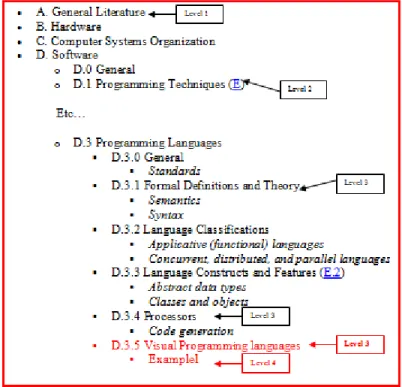
In 1993, Burnett and Baker proposed a classification system for visual programming languages [2]. As the literature of VPLs was broadening, they sensed that the development of a classification system to help researchers find the right material was a necessity. Although a similar computing reviews system already was designed by the Association for Computing Machinery (ACM), Burnett and Baker came to the conclusion that this system was not suitable for classifying VPLs. The ACM computing classification system is a four-level tree; placing VPLs under classification D3 (Programming Languages) would mean that only one more level could be added underneath VPLs. But, defining VPLs is more complex, and therefore, more than one subsection is needed to classify VPLs properly. However, for Burnett and Baker, this limitation could not satisfactorily classify the work in VPLs. Figure 2.2.1 shows an explanation of the levels in the ACM computing review system and the limitation for adding VPLs as a level-3 leaf in the tree, and figure 2.2.2 shows the classification of VPLs that Burnett and Baker proposed.
17
Figure 2.2.2: VPLs Classification system [3]
For the purpose of this research Burnett and Baker's classification system is used to categorize VPLs, even though this classification originally was designed to help researchers find proper research materials in the VPL areas. A given VPL can be categorized at the same time under the section VPL II – Language classification (by paradigm or visual representation) – and also under the section VPL V – Language Purpose. The other sections are engaged more specifically with visual programming language features than with the taxonomy, and thus could be disregarded if one‘s purpose is to find some sort of hierarchical taxonomy.
2.3 VPL Grammar
Describing a textual programming language in Backus Naur Form (BNF) is possible because only one type of relationship is allowed between symbols: the relationship next to [4]; thus there is no need to define the specific type of relationship. However, formally
18
specifying a VPL is more challenging, since there is more than one relationship that needs specifically to be added to the grammar.
In 1994, Kim Marriot presented a framework to formally define visual languages—the constraints multiset grammar (CMG) [4]. He proposed a theoretical foundation to generate a parser from a grammar describing a visual language. The parser takes as input a multiset of strings, lines, arcs, circles etc. Marriot states that for visual languages, grammars and parsers use multisets instead of sequences, because in general, people do not follow the same order when drawing complex diagrams.
Marriot explains that CMGs differ from traditional string grammars in two ways: 1. String grammars rewrite sequences of tokens, but multiset constraint
grammars rewrite multisets of tokens.
2. String grammars have only one type of relationship, which is ―next to‖, but multiset constraint grammars have a wider number of relationships, such as intersection, next to, above, below etc.
Constraints are used in a CMG to define the relationship between components. A CMG over a computation domain D is defined formally by Marriot as being composed of:
- a set of terminal type symbols, TT - a set of non-terminal type symbols, TNT - a distinguished start type symbols, ST ∈ TNT - a set of productions
The language of the grammar will be the set of all sentences that can be generated from the start symbol using the productions in the grammar.
Marriott defines that in a constraint multiset grammar, a production is of the form: S ::= S1,…,Sn C on S‘1,…,S‘m
where S is a non-terminal symbol that can be rewritten to the multiset of symbols S1,…,Sn and C is a set of constraints on the attributes of other symbols S‘1,…,S‘m. Marriott defines the constraints C as elements that enable the encodement of spatial layouts and relationships between a diagram and its components in the grammar.
Marriott gives the following production example: P:state ::= Q:circle, T:text
19
where Q .midpoint = T .midpoint, 2 * Q.radius >= T.height, 2 * Q.radius >= T.width, P.midpoint = Q.midpoint, P.radius = Q.radius, P.name = T.string, P.kind = normal. In this production:- Q .midpoint = T .midpoint constrains the midpoint of the text so that it is the same as the midpoint of the circle; therefore the text and the circle share a common area. - 2* Q.radius >= T.height informs that the text height fits in the circle
- 2 * Q.radius >= T.width informs that the text width fits in the circle
It can be deduced that the text is entirely in the circle, and that the text is perfectly centered in the circle.
- P.midpoint = Q.midpoint the center of the production is the center of the circle. - P.radius = Q.radius the radius of the production is the radius of the circle. - P.name = T.string the name attribute of the production is the text value of T. - P.kind = normal the production is of the type or kind normal.
In his study Marriot unfortunately found out that parsing a sentence to find if it belongs to the language of a CMG is an undecidable problem because CMGs can emulate two-counter machines. Indeed, this is based on the fact that the halting problem for two-two-counter Turing machines is unsolvable, as proved by Pierce from the Carnegie Melon School of Computer Science [5].
The details of the formal description of these CMGs are outside the scope of this research; therefore, this section presents only the result of Marriot's studies. After
investigating CMGs that are cycle free, Marriot came to the conclusion that the complexity of parsing a cycle-free CMG is not polynomial but exponential, but parsing a fixed deterministic
20
CMG has a polynomial complexity. The analysis of his results determined that the complexity of CMGs is in between that of string grammars and constraint logic grammars.
The research results presented by Marriott give a sense of the difficulty in formally specifying a VPL using a grammar, thus, the formal specification of UVPL will not be covered in this research.
2.4 Cognitive Dimension of VPLs
The primary purpose for the development of VPLs is to provide usability. However, development of VPLs seldom includes tests to show whether or not a VPL is usable.
T.R.G. Green proposes a method based on cognitive walkthrough to help designers of VPLs detect the level of usability they have achieved [6]. His paper elaborates on the human computer interaction (HCI) technique known as cognitive walkthrough. This technique is used to detect and correct usability problems on a user interface.
Cognitive walkthrough is a tool that was designed originally for testing usability in the engineering field. Green states the four phases of this approach:
1. Set a goal to be accomplished
2. Search the interface for available actions
3. Select an action that seems likely to make progress toward the goal 4. Perform the action and check to see if progress is made towards the goal. Green declares that cognitive walkthrough is a good method to evaluate the use of VPLs for the following reasons:
- The development of a program using a VPL usually is done through a GUI. The cognitive walkthrough method focuses on a user's ability to figure out how to use a new UI; therefore, it is beneficial to use a cognitive walkthrough method to test the usability of VPLs.
- Usually computer scientists do not have a background in cognitive science;
however, the cognitive walkthrough method—unlike other HCI approaches—seems more easily usable by computer scientists that are not familiar with cognitive science.
21
In his paper, Green describes a method he calls the WYSIWYT (what you see is what you test) methodology that he uses to test the VPL Forms/3; this visual language was developed by Burnett and Ambler in 1991 [9]. Green shows that this method did not yield good results, and that refining this method with cognitive walkthroughs produced better results.
Finally, Green concludes that cognitive walkthrough is a method with limitations, since it cannot evaluate the cost of making an error, for instance. Nevertheless, cognitive
walkthroughs perform faster than pilot analysis or protocol analysis, and the focus of this method is on specific areas in a subtask, which helps to target specific design issues.
2.5 Short VPL Survey
The following section presents a brief survey of different types of domain specific VPLs. Alternate Reality Kit (ARK) [7]: implemented in Smalltalk-80, ARK was developed around 1986 by Randall Smith. It is a virtual world programming environment and can be classified as a domain-specific VPL, since its sole purpose is to aid in the simulation of the fundamental laws of nature via a 2D animated environment. ARK is a system developed for a non-programmer audience that needs to understand the laws of nature, like gravity or friction. This VPL enables the users to grasp the concepts of physical laws by allowing them to apply the simulated laws to physical objects via virtual simulation. In ARK, objects are images that have a position and velocity, and to which forces can be applied. A user manipulates a given object with another object, a hand, which is controlled using a mouse. ARK allows the user to simulate the physical laws in their very basics, whereby the full details of reality are not implemented; instead, the user directly simulates the effect of an action, rather than all the different small reactions that lead to the final action. Smith gives the example of the
implementation of an electrical switch; the user does not simulate the physical installation of a button where electrical lines are connecting the switch to the power supply, but the button is visualized, and pushing it on or off will have a simulated reaction.
In ARK, users interact with the objects through a GUI; they also can create new kinds of objects and add them to the library of built-in objects in the ARK warehouse.
22
1. The application level user who typically just runs a simulation 2. The simulation builder who builds a simulation application
3. The lowest level user who builds tools to be used by the simulation builder. An important issue to point out about ARK is the use of the mouse to operate what is called the hand object. It has been observed that use of the mouse to operate the hand is not intuitive, and confuses a lot of users [7]. Indeed, many computer mice have only two buttons (left and right), yet a hand can grab, pull, push, release etc., which means that the mouse cannot, in an easy manner simulate all the different capabilities of the physical hand. However it is very easy to learn the idea behind ARK and its concepts.
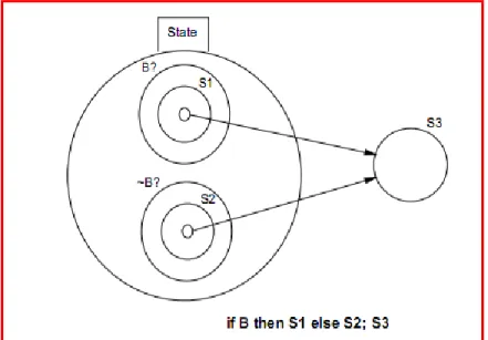
Visual Imperative Programming (VIPR)[8]: VIPR was developed at the University of Colorado by Wayne Citrin. VIPR is not an iconic VPL; instead of text or icons or graphs it uses nested concentric rings to convey the semantic of a program. From one step of the program to another, inner rings are being merged while the outermost ring is connected to the state. Figure 2 shows how VIPR represents an ―if‖ statement.
Figure 2.5.1: static VIPR representation of an if statement [8].
The development of VIPR was motivated by the desire to have an object-oriented language that is easy to learn and use; therefore, VIPR has all the features of an
object-23
oriented language: inheritance, polymorphism, and dynamic dispatch, to name a few. The semantics are similar to C++, thus VIPR can be used for low or high level programming.
An expression oriented component, VEX, which is used for lambda calculus, also was added to VIPR. Lambda calculus is a notation to describe computable functions.
Prograph [9]: developed by Cox and Pietryzkowsky around 1990. Several versions have been released, and the latest one is Prograph/CPX. It is an object-oriented visual language that combines visual dataflow specifications with notions such as classes and
objects. Prograph is an imperative language, which is a programming paradigm that describes computation in terms of statements that change the state of a program and the statements are executed in a sequential manner. In Prograph, cases and multiplexes are control structures used to replace explicit iteration by a sophisticated flow control. Prograph also provides persistent objects that are stored in a database. Methods are built up as
accumulations of cases; each case in a method is a dataflow diagram that describes how the case should be executed. The diagrams are comprised of inputs, outputs and a set of
operations; these entities are all connected. In Prograph, the order of execution is data-driven: the edges in a flow diagram indicate the data flow from one operation to another.
Visual TPL [10]: Visual TPL was proposed by Tu, Chen and Cheng, as the result of a research they conducted. This language is a domain-specific VPL, as its only use is for transforming data for generating reports. The inputs for a Visual TPL program are tables that come from a database. This language has four native components: table, helper, aggregation, and data source. A table component transforms one table into another. The resulting table typically is the data used in reports. The helper component is a collection of functions used for transforming data, and the functions are grouped as arithmetic, logical and relational
operations. The aggregation component is another tool for data transformation, and it permits the programmer to perform aggregates such as averages, counts etc. The last native
component Tu, et al. present in their report is the data source component, which is basically the component that will connect to a database to provide requested tables. The programmer also can combine preexisting components to make a composite one. The authors mention that
24
the construction of composite components can be viewed as performing abstraction since the subcomponents used in a composite component are hidden.
A Visual TPL program is developed using an environment called Visual TPS, and this environment was designed specifically for Visual TPL. Tu. et al. describe the environment as having five areas. One area has icons for the native components, and another area is designated for the composite components; the components from these two areas can be dragged and dropped into a third area, which is a canvas where a program is built. All the components dropped on the canvas are linked by connectors that will drive the flow of the program. The fourth area in the Visual TPS environment is a display for immediate feedback, allowing the programmer to preview the result. The last area makes the components most used by the programmer easily accessible. The authors claim that the Visual TPS environment, which generates reports by designing a graphical data flow program, is easy to use and intuitive.
2.6 Scaling up Visual Programming Languages
The scalability issue is an important one for the viability of VPLs. Even though using visual languages can be a very interesting approach for editing a program, their usefulness has been affected by the inability of these languages to uphold large projects. Burnett and Baker describe this issue as "how to expand applicability without sacrificing the goals of better logic expression and understanding" [11].
In their paper, they discuss some issues pertaining to scaling up VPLs and some possible solutions, described below.
Static representation of a program, which is the complete representation of a program at rest, is de facto in traditional TPLs; however for VPLs – and more particularly interactive VPLs — it can be difficult to represent the entire program statically. Consequently, the review of a VPL program can be a difficult task. Some ideas that have been proposed would resolve this issue, but at the price of a VPL partially losing its visual nature. For instance, Burnett and Baker mention the translation of the program to a textual program for static representation; however this solution defies the purpose of VPLs, since the result of that transformation is a textual program. The usefulness of a VPL program representation is
25
measured by evaluating the editability vs. the ability of a VPL to achieve some level of abstraction to hide excessive visual details.
Management of Screen real estate is another important problem, because of the nature of visual languages. It is challenging to edit and display a large visual program if the ratio of screen size to visual object size is too small. This issue involves how to display a large enough part of a VPL program to represent a logical block within the program. Burnett and Baker state that one solution to this problem is the use of scroll bars, but this solution would need to be coupled with others to be effective.
Burnett and Baker raise another issue concerning the incorporation of internal documentation in a VPL; this issue is solved in TPLs by the use of in-line comments ignored by the compiler. Documentation participates in scalability, because any type of documentation needs space—whether the documentation is always apparent, or whether the documentation is a dynamic text, where the text only appears at certain events such as a ‗mouse over‘. Some VPLs can be, by their nature, self-documenting, which alleviates the need for extra, explicit documentation; however, for VPLs that do not have implicit documentation, other solutions have been used. The VPL Forms/3 uses a form of documentation that is neither text, nor does it use space; rather, visual markers such as, coloring or boxing and lining perform the work of documentation. Another type of documentation, named ad-hoc documentation, also has been used; since the purpose of documenting is to help the reader of a program understand it better, hoc documentation is a technique that tries to achieve this goal by providing an ad-hoc animation that displays the computation and the intermediate values for a portion of the program.
For a modern programmer the use of procedural abstraction is taken for granted, but in the early days of programming, it was considered as an important step forward. Similarly for VPLs the ability to reduce a logical portion of a program to an icon is considered an advanced way to apply procedural abstraction, and is considered a big contribution to the ability to scale up VPLs.
Jamal and Wenzel, in research on the scalability of LabView, point out that the criticism that has affected VPLs mostly is the lack of visual abstraction methods [12]. They explored the scalability of LabView and the abstraction mechanisms present in this language
26
that help in managing large scale programs. Such mechanisms include icons on a diagram to describe its functionality. Another mechanism is the reuse of a diagram that was previously iconified.
Data abstraction—which is the use of user-defined data types—is as important as procedural abstraction. Burnett, et al. state that this object-oriented feature can contribute to the problem of VPL scalability [11]; even though data abstraction contributes in achieving a high level language, it might prevent interactivity. Proper access of a user-defined object is allowed only through operations defined in the data type of the object; if those operations are not visual, but rather textual, there is a possibility of losing interactivity or visibility [11].
In order to address this issue, a VPL that supports data abstraction needs to meet — according to Burnett and Baker—the following requirement: a VPL that supports data
abstraction should provide a visual process to define a new data type, which also results in a visual program.
Finally Burnett, et al. discuss the relationship between programming language efficiency and scaling up a VPL. As most VPLs strive to supply immediate feedback, the need to provide responsiveness can affect the efficiency of a program, since the program will need to be translated and executed more often than a program in a language that does not provide immediate visual feedback.
2.7 Iteration constructs in VPLs
Another important issue in designing VPLs is the design of program control constructs, such as iteration. The nature of VPLs might make the representations more challenging. The biggest challenge in VPLs regarding the mechanisms of iteration is how to provide a compact viprocon with enough information to represent them properly. In the particular case of data flow VPLs, the issue is how to provide a mechanism for iteration without violating the very nature of a data flow paradigm. Mosconi and Porta, two researchers from the University of Pavia in Italy wrote a paper that presents the minimum set of characteristics to implement iterations in a data flow VPL, and they also show some types of iterations that could be implemented using the characteristics they defined [13].
27
Mosconi and Porta survey different iteration mechanisms adopted by several data flow VPLs such as LabView and Prograph, and they argue that some of these mechanisms do not respect the data-flow paradigm, even though they do contribute to a simplified user
interaction. Mosconi and Porta state that one rule that should be followed in data flow
languages is to avoid cycles; however, they notice that all the VPLs they studied use cycles to implement the constructs for their iteration. This is why the authors came to the conclusion that some data flow VPLs do not respect the data flow paradigm. They agreed that using cycles to represent data flow in iterations works, but they also studied others aspects of the data flow model to help implement better iterations.
Their studies allowed them to come up with four definitions, three theorems and six corollaries that describe pure data flow VPLs. Some relevant ones are given below.
Definition 1: A pure, data-driven, data-flow VPL is one that is made up only of nodes (visual elements representing functions, variables, constants) and links (visual elements connecting the nodes).
Definition 3: A pure, data flow VPL sub-graph is said to be iterative if there exists a function A in the sub-graph such that at least one of its inputs derives from an output of another function B for which, in turn, at least one input derives from an output of A (vice versa).
Theorem 1: In a pure, data-driven, data flow VPL it is not possible to implement an iterative behavior unless at least one function in the looped sub-graph receives more than one link for the same input.
Corollary 1: If a pure, data-driven …, data flow VPL does not allow functions to receive more than one link for the same input, iterative behaviors can be obtained by
introducing into the language a special element that has two or more inputs and that behaves in the following way: it fires whenever one of its inputs is available; simply emitting that input as an output introducing the special element means that the data flow VPL is no longer pure.
With respect to these characteristics and some others that are not quoted here, Mosconi and Porta described in the remaining part of their paper the implementations of some iteration constructs that use enabling signals to avoid synchronization issues possible with inhibitor signals.
28
2.8 Arrays representation in VPLs
Allen Ambler published two papers pertaining to the representation and manipulation of data structures such as arrays in VPLs. He states that manipulating arrays in textual languages always has been a difficult task, especially for the non-trained programmer, since all manipulations have to be done through indexing. A certain level of abstraction in a visual language definition can allow certain kinds of operations on arrays without the need to index in any way. In his papers he proposes a different representation of arrays and also describes their manipulation [14] [15].
In his representation, arrays are represented by cells, and the user can choose to display scroll bars, since the array could be of any dimension.
Figure 2.8.1 Array of 2 dimensions with scroll bars [14]
Arrays can be split into multiple parts called regions. Formulas or expressions can be applied to a whole region rather than just a cell, and therefore the user never has to deal with indexing.
Allen gives a few examples of manipulating arrays using his technique in the VPL Formulate. For instance, appending two arrays is performed by just providing to the function the two arrays to append. He also shows how arrays can be partitioned to form new regions by selecting and dragging borders. He demonstrates how summing a vector or a list could be done by creating a second vector or list that will carry along the partial sum of the elements, and thus the last element will contain the sum of the entire array, as shown in figure 2.8.2.
29
Figure 2.8.2: Summing a list in Formulate [14]
However by attempting to solve the Eight Queen problem, Allen concludes that not all the problems involving arrays can be solved without explicitly indexing the array.
One can come to the conclusion that representing arrays and manipulating them can be facilitated to some extent by providing the users some functions for the most common tasks, giving them the ability to build their own functions and providing them the ability to index the arrays. If the goal is to provide an easier way to manipulate arrays to inexperienced programmers, the goal can be achieved with built-in functions such as ‗append array‘, ‗sum a list‘ etc. The experienced programmers who already understand how to manipulate arrays can use either the built in functions or make up their own, as they most likely will be the users that will need more than just the built-in functions. Finally, displaying arrays as cells implies that the programmer probably prefers entering values or formulas into the cells rather than using indexing. The programmer many times does not know these values, and inserting formulas into the cells is not an elegant solution; thus, it might be preferable to abstract the structure of arrays in VPLs in order to better manage the edit area.
30
2.9 Principles of programming languages
In the book Principles of Programming Languages, McLennan aspires to provide descriptive tools, which he suggests are important for designing programming languages [16]. He insists that these principles are not laws that absolutely have to be followed; also, they are neither axioms nor a set of formal constraints. Further, some of these principles of
programming languages cannot be applied at the same time because they contradict each other. Also, some principles may complement each other. It then becomes difficult to know which principles to adopt. Furthermore, unlike principles such as scientific laws, the principles of programming languages do not have quantitative measurements yet; therefore, McLennan suggests making tradeoffs based on qualitative judgments. The principles defined by
McLennan that are used in this research are the following:
- The responsible designprinciple: find out what users need, not what they want. - The automation principle: automate mechanical or error-prone activities.
- The syntactic consistency principle: similar things should look similar and different things different.
- The defense in depthprinciple: if an error is not caught by one defense, it probably will be caught by another.
- The information hidingprinciple: the user has all information needed to use a module and nothing more; all information needed to implement a module is provided and nothing more. - The security principle: if a program violates its language definition or intended structure, the violation should be detected.
- The abstractionprinciple: avoid anything to be stated more than once. - The eleganceprinciple: designs look good because they are good.
- The simplicityprinciple: use a minimum number of concepts, with simple rules for their combination.
- The impossible errorprinciple: making errors impossible to commit.
- The orthogonalityprinciple: independent functions should be controlled by independent mechanisms.
- The preservation of informationprinciple: representation of information that user might know and compiler might need.
31
- The structureprinciple: the visual form of a program leads the user to visualize its behavior. - The 0 – 1– ∞principle: zero, one and infinity are the only reasonable numbers.[16].
32
Chapter III
METHODOLOGY
3.1 VPLs Selection Process
As a starting point, some visual programming languages (VPLs) are selected for a short survey. The starting list was composed of 43 currently available VPLs; each of these languages was considered for inclusion in the survey based on the following characteristics: the language purpose, the availability, the type of support available, the platforms supported and whether or not it is a teaching tool.
The language purpose is an important criterion, because some languages that are too specific, such as languages to edit music.
- Because this research in not funded, the availability criterion is used to eliminate the languages that are not freely available and the languages that do not provide free support.
- The study is conducted entirely on a Microsoft Windows machine, and so only languages available on Windows platforms are considered.
- VPLs used as teaching tools might not be good examples for designing a language for scalable programs; however, they probably have features that can be
33
Applying these criteria, the list of VPLs was reduced to 10, as shown in Table 3.1-1 below.
VPL Purpose availability Platform Support Teaching tool
AgentSheets game Trial Mac / Win yes No
Alice game yes Lin / Mac / Win yes Yes
Analytica spreadsheet Trial Win yes No
Labview testing, control device Trial Win yes No
Lily Web dev. yes Lin / Mac / Win yes No
Microsoft VPL robotics yes Win yes No
PointDragon Web dev yes browser yes No
Simulink /Matlab math Trial Win yes No
Tersus Web dev yes Win / Lin yes No
VisSim hardware testing Trial Win yes No
Table 3.1-1: VPLs to select from
From these remaining VPLs, one from each purpose category was selected arbitrarily, and the list of VPLs chosen for use in this study was reduced to Alice 2.2, Lumina Analytica 4.2, Microsoft VPL 2.1 and Tersus 1.3.
Alice is a VPL designed for high school and college students. It uses 3D graphics to teach introductory computing to an audience already familiar with videogames. Programs are built on a drag and drop interface. The 3D objects that are provided by Alice are used to create virtual worlds, and the program animates those objects.
Analytica is used to create and manipulate decision models. It is not a teaching tool. The user creates models by dragging to the work area viprocons (visual programming icons) that represent decisions, variables, chances, objectives, modules, indices, constants,
functions, and text. The viprocons are connected with arrows that represent the flow of data. Each node has a definition that can be written with a procedural language very similar to Pascal. Analytica has 11 system libraries, and the user also can build more libraries.
34
Microsoft Visual Programming Language (MS VPL) is part of Robotics Developer Studio. It is a dataflow VPL and supports concurrency. MS VPL is designed for novice programmers, but also can be used by professionals. It is designed mainly for robotics programming, but also can be used for general purpose programming. The user manipulates blocks that are connected with arrows. Blocks such as the ―If‖, ―Calculate‖, or ―Case‖, have expressions similar to C#. Libraries are wrapped around decentralized software services. Users can create their own services in C#, and can edit the not escape preexisting ones.
Tersus is designed for web application development. It is not a teaching tool. Tersus is a data flow programming language, and so the blocks in the diagrams need to be connected with arrows. A Tersus program has a top-down design, and is composed of web services, and built-in or user-defined components. The Tersus work area is called an ―infinite drawing board,‖ because the top model represents the system, and the user drills down to specify the components of the system and the details of those components, and the user can continue to drill deeper and deeper.
3.2 Analysis of principles for the selected VPLs
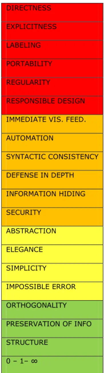
A design analysis needs to begin by laying down the principles that should be followed. For this purpose, a compilation of strategies from Burnett [1], who has focused her research on visual programming and especially on achieving scalability with VPLs, and principles from McLennan [16] are compiled in
Table 3.2-1. These strategies and principles are described in sections 2.4 and 2.5 of this thesis, and are used throughout this section to analyze the grokens and viprocons of the selected VPLs and later UVPL. The following sections describe the analysis of the categories of the programming constructs.
35
Table 3.2-1: List of Strategies and principles DIRECTNESS EXPLICITNESS LABELING PORTABILITY REGULARITY RESPONSIBLE DESIGN IMMEDIATE VIS. FEED. AUTOMATION SYNTACTIC CONSISTENCY DEFENSE IN DEPTH INFORMATION HIDING SECURITY ABSTRACTION ELEGANCE SIMPLICITY IMPOSSIBLE ERROR ORTHOGONALITY PRESERVATION OF INFO STRUCTURE 0 – 1– ∞
36
3.3 Variables and literals
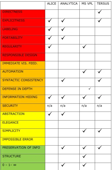
The analysis of variables in the VPLs selected for this research helps to determine which languages follow, or do not follow, the identified principles. Some examples related to variables and literals are given, and the analysis is summarized in Table 3.2-2.
The directness strategy:e.g. naming a variable should be done directly on the groken rather than by entering the name in a property window, since the name of the variable is part of the groken.
The explicitness strategy:e.g. the flow of data should be visually or textually explicit. Arrows can be used to direct the data flow explicitly. Keywords such as set get or the equal sign can be used as well to show whether a value is being assigned to a variable or a value is being retrieved from a variable.
The labeling principle: e.g. the memory location of a variable is not used to manipulate it, instead its name is used.
The portability principle: e.g. the data type of a variable should not be specific to a subset of machines architecture.
The regularity principle: e.g. in a language all variables are initialized automatically, or none of them are initialized automatically.
The responsible design principle: e.g. it would be irresponsible to design a language that provides to the user only integers of precision 128 so that a novice programmer will not have to worry about which precision to use. A responsible approach provides to the user integers of different precisions.
The immediate visual feedback principle: e.g. the value of a variable shall be displayed as the program is being edited, provided no run time value is needed.
The automation principle: e.g. the declaration of a variable is one of the activities where errors commonly occur. A common error made by novice programmers is to use a variable in the code without declaring it. This declaration could be performed automatically.
The syntactic consistency principle: e.g. the grokens for variables shall all look similar and they shall look different from other programming constructs.
37
The defense in depth principle: e.g. if the user can assign a string value to an integer variable while editing a program, the system should catch that error when an expression uses that variable.
The information hiding principle: e.g. for a string variable, the user will be provided all the string operations the language provides, but the system will hide the operations for
integers.
The abstraction principle: e.g. two pieces of information are not needed to identify a variable as being an integer.
The elegance principle: e.g. this principle is violated if the groken for a variable is a really complicated geometric figure,. Add more about having choice of a simpler design.
The simplicity principle: e.g. the concepts should be simple.
The impossible error principle: e.g. mechanisms such as not allowing a string literal to be assigned to an integer variable can be implemented to avoid those errors.
The preservation of information principle: e.g. the user declares a variable to be of a certain type, and the system keeps track of that type.
The structure principle: e.g. use of a unidirectional arrow to represent assignment of the content of a variable to a different variable.
The 0 – 1– ∞ principle: e.g. the maximum dimensions of arrays should not be limited to arbitrary numbers such as 4 or 7; the language should either not allow arrays (0), or allow only arrays of one dimension (1) or allow arrays of any dimension (∞).
38
ALICE ANALYTICA MS VPL TERSUS DIRECTNESS EXPLICITNESS LABELING PORTABILITY REGULARITY RESPONSIBLE DESIGN IMMEDIATE VIS. FEED. AUTOMATION
SYNTACTIC CONSISTENCY
DEFENSE IN DEPTH
INFORMATION HIDING
SECURITY n/a n/a n/a n/a
ABSTRACTION ELEGANCE SIMPLICITY IMPOSSIBLE ERROR PRESERVATION OF INFO STRUCTURE 0 – 1– ∞
39
Strength and Weaknesses of Variables in Alice Strengths:
Even though immediate visual feedback – as defined by Burnett – is not provided in Alice, the user can watch the values of the variables being updated when the program is running. The data type and the value assigned to the variable are presented visually and explicitly as shown in Figure 3.2.1.
Figure 3.2.1: Example of a variable in Alice
Figure 3.2.2: Syntactic consistency violation
Figure 3.2.3: Example of a variable with a long name
Weaknesses:
Alice lacks direct manipulation of the variable grokens, leading assignments to be very cumbersome. One goes through several selection menus to assign to a variable a number, the value of a different variable, or the value of an expression. In Alice, a variable looks different when used in an expression than when declared, as shown in Figure 3.2.2. Figure 3.2.3 shows how variable grokens do not have a fixed size, whereby the icon grows as the name gets
40
longer; this can lead to issues for screen real estate. All numbers in Alice are double precision floating point.
Strength and Weaknesses of Variables in Analytica Strengths:
Analytica does not provide typed variables, however the type is deduced when operations are performed against the variables.
Figure 3.2.4: example of a variable in Analytica
Figure 3.2.5: some grokens and viprocons in Analytica
Weaknesses:
The variable grokens in Analytica as depicted in Figure 3.2.4 are not manipulated directly; all interactions are effectuated in secondary screens, using a procedural, textual, language. Some grokens and viprocons, such as variables and modules are very similar to each other as shown in Figure 3.2.5, and furthermore the user has the option to make them
41
look identical by setting them to the same color. The behavior of the program is not visualized easily, as values assigned to variables are not shown explicitly.
Strength and Weaknesses of Variables in Microsoft VPL Strengths:
In MS VPL, regardless of the data type, all variables look the same and are differentiated from other grokens and viprocons by the color and the object label.
Figure 3.2.6: Example of a variable in MS VPL
Weaknesses:
The variable a groken represents is interchangeable at any point during editing by simply choosing a different variable from the dropdown, as seen in Figure 3.2.6. On one hand this feature adds convenience to programming, since on most VPLs changing a variable requires the groken to be deleted and replaced. But on the other hand this feature can be error prone.
Strength and Weaknesses of Variables in Tersus Strengths:
Unlike in MS VPL, variable grokens in Tersus consistently receive data from their left side and output data through their right side, consequently leading to a simple design. The declaration of a variable is automated, whereby the user only needs to drag and drop the groken and starts using it.
42
Figure 3.2.7 shows how the data type is unnecessarily stated twice on the groken; nevertheless, the data type tags on the variable groken are persistent, which can help during editing of a program.
Figure 3.2.7: example of a variable in Tersus
3.4 Arithmetic, Boolean, and Comparison Operations An operation groken accepts operands, and produces a result after some
computation(s) are performed on the operands. The way in which these actions are performed in Alice, Analytica, MS VPL and Tersus are analyzed in this section, using the same strategies and principles described earlier in this chapter, and the findings are summarized in Table.
43
ALICE ANALYTICA MS VPL TERSUS DIRECTNESS
EXPLICITNESS
LABELING n/a n/a n/a n/a
PORTABILITY REGULARITY
RESPONSIBLE DESIGN
IMMEDIATE VIS. FEED.
AUTOMATION n/a n/a n/a n/a
SYNTACTIC CONSISTENCY DEFENSE IN DEPTH INFORMATION HIDING
SECURITY n/a n/a n/a n/a
ABSTRACTION ELEGANCE SIMPLICITY
IMPOSSIBLE ERROR ORTHOGONALITY
PRESERVATION OF INFO n/a n/a n/a n/a STRUCTURE
Table 3.2-3: Principles related to operations
To put into context Burnett‘s strategies and McLennan‘s principles, some examples are provided to relate them to the operations analyzed in this section.
The directness strategy: e.g. arguments should be directly assigned to an operation by the use of arrows or other directive components.
The explicitness strategy: e.g. the purpose of the operation should be visually explicit; if it is an addition the operation groken should have the name or the symbol of the operation in it.
44
The regularityprinciple: e.g. all operations should accept arguments on a particular side (such as the left side) and output results from a different side (such as the right side).
The responsible designprinciple: e.g. the language should not permit a programmer to rename a built-in operation.
The immediate visual feedbackprinciple: e.g. the result of an operation is displayed as the program is being edited.
The syntactic consistencyprinciple: e.g. all grokens for categories of operations should have the same look and feel.
The defense in depthprinciple: e.g. if the VPL development environment fails to catch that not enough arguments are given to an operation, this error should be caught later in the editing process of the program, as the output from the operation is being used in another operation.
The information hidingprinciple: e.g. when the user is manipulating string variables, arithmetic operations should be disabled or hidden from the user.
The abstractionprinciple: e.g. two sorts of information are not needed to define an operation – like having the word "addition" and the symbol ―+‖ used in the same groken.
The impossible errorprinciple: e.g. the example provided for the information hiding principle , reduces the likelihood of programmer error.
The orthogonalityprinciple: e.g. using the addition operation to perform additions and subtractions would be a lack of orthogonality.
The structureprinciple: e.g. the use of a unidirectional arrow to represent the result of an operation being sent to an output argument.
Strength and Weaknesses of Operations in Alice Strengths:
Alice has an approach that follows information hiding, whereby the contextual menus do not display string functions when the variables being manipulated are numbers.
45
Figure 3.2.8: addition in Alice
Figure 3.2.9: comparison in Alice
Weaknesses:
In Alice there is no notion of grokens to represent operations, and thus the operations are closer to being textual as illustrated in Figure 3.2.8 and Figure 3.2.9. Manipulating
operations is not simple, because the user builds expressions entirely through selection menus. Floating point division is provided, but integer division is not; this is a direct effect of the lack of orthogonality in the design of variables, since in Alice all numbers are double precision floating point numbers.
Strength and Weaknesses of Operations in Analytica Strengths:
It is not readily apparent that Analytica strongly complies with Burnett‘s strategies and McLennan‘s principles.
46
Figure 3.2.10: Example of Operation in Analytica
Weaknesses
Similar to VPLs such as MS VPL the user types expressions in a textual, procedural, language, and thus all operations are textual, as shown in the property form in Figure 3.2.10.
Strength and Weaknesses of Operations in MS VPL Strengths:
If an operation is adding a string to an integer, an error occurs if the result is being set as shown in Figure 3.2.11.
Figure 3.2.11: invalid operation in MS VPL Double click on “adjusted rank”
47
Weaknesses:
In MS VPL, the operations are not iconic – they are textual, and are used like TPL operations.
Strength and Weaknesses of Operations in Tersus Strengths:
Tersus operations have dedicated grokens, and in general follow the defense in depth principle, such as detecting when an integer is being added to a string as shows Figure 3.2.12.
Figure 3.2.12: Invalid operation in Tersus
Weaknesses:
The user has the ability to rename an operation – for example, addition – to meaningless or misleading names such as ‗division‘, ‗&‘ etc.; this feature gives the user the freedom to name an operation anything, but on the other hand it can lead to maintainability issues, if the programmer does not use it responsibly.
3.5 Control Flow
The result of the analysis of the control flow from the selected VPLs is presented in Table 3.2-4.
48
ALICE ANALYTICA MS VPL TERSUS DIRECTNESS
EXPLICITNESS
LABELING n/a n/a n/a n/a
PORTABILITY
REGULARITY n/a n/a n/a n/a
RESPONSIBLE DESIGN IMMEDIATE VIS. FEED. AUTOMATION SYNTACTIC CONSISTENCY DEFENSE IN DEPTH INFORMATION HIDING SECURITY ABSTRACTION ELEGANCE SIMPLICITY IMPOSSIBLE ERROR
ORTHOGONALITY n/a n/a n/a n/a
PRESERVATION OF INFO STRUCTURE
Table 3.2-4: Principles related to control flow
What follows are examples of applications of the strategies and principles related to control flow:
The directness strategy: e.g. "for loop" counters or "while loop" conditions could be assigned directly to a control flow viprocon by the use of arrows.
The explicitness strategy: e.g. the purpose of a control flow should be visually explicit; the viprocon should have the name or the symbol of the type of the control flow construct. The programmer should not have to infer the type of control flow.
49
The responsible designprinciple: e.g. the language should not permit an instruction within a loop to jump to any other part of the program except to the statements of the loop or to the statement right after the loop.
The immediate visual feedbackprinciple: e.g. the language allows the display of the value of a counter as a "for loop" is unfolding.
The automation principle: e.g. the language should provide the option to increment counters in iterations automatically.
The syntactic consistencyprinciple: e.g. the viprocons for all control flow should have a similar look and feel.
The defense in depthprinciple: e.g. the programming language could generate a warning if an infinite loop is detected; this could be useful to novice programmers.
The information hidingprinciple: e.g. a control flow viprocon should not request more information from the user than is needed to start or stop iterations.
The security principle: e.g. if a loop runs infinitely, all resources could be consumed, which in turn could lead to security issues.
The abstractionprinciple: e.g. a conditional loop should be implemented in such a way that the condition itself is stated only once, either at the beginning of the loop or at the end of the loop, instead of both at the beginning and at the end, or at the beginning of each case value.
The impossible errorprinciple: e.g. mechanisms that could detect possible infinite loops should be encouraged.
The orthogonalityprinciple: this principle is not applicable because, e.g., writing a for loop as a while loop is not a bad design
The preservation of informationprinciple: e.g. representing a stopping condition in a "for loop" is an example of preserving information that the user knows and the compiler needs.
The structureprinciple: e.g. symbols to represent the beginning and the end of a loop could be used to add structure in a control flow viprocon.
50
Control flow in Alice Strengths:
Alice provides a lot of automation, whereby counter variables are created
automatically if the user does not specify any; there is also an option to set automatically a loop to run infinitely. Figure 3.2.14Figure 3.2.13 illustrates how in Alice the beginning and the end of a loop can be distinguished visually; indeed, a control flow block is represented by a distinctly-colored rectangle.
Figure 3.2.13: While loop in Alice
51
Weaknesses:
Figure 3.2.14 shows how in Alice for loops do not decrement, and when incrementing by (-1) – to perform a decrement – the program halts without throwing an error or returning any results. Furthermore, in the for loop an existing variable cannot be used as the loop index; Alice creates that index automatically.
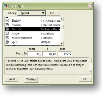
Control flow in Analytica Strengths:
If the programmer defines the statements to execute in a control flow using undeclared variables, Analytica creates these variables automatically.
52
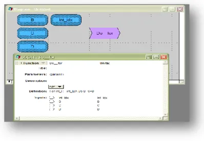
Figure 3.2.16: Indirectness in Analytica.
Replace this image with added function.
Weaknesses:
In Analytica, the control flow viprocons are the same as the function viprocons, and even though the control flow constructs are considered to be special functions, they cannot be distinguished from regular functions as shown in Figure 3.2.156. The user never manipulates directly the control flow viprocons; instead there are additional windows where the indices and conditions are specified as shown in Figure 3.2.16. Neither control flow nor iteration viprocons are visually explicit, so the programmer needs to give the viprocons a proper name.
Control Flow in Microsoft Visual Programming Language Strengths:
The design of control flow in MS VPL has syntactic consistency; those viprocons are grey in contrast to red and green for variables and data as illustrated in Figure 3.2.18. The structure of the viprocons helps visualize their behavior for different outcomes.
53
Figure 3.2.17: If viprocon in MS VPL
Figure 3.2.18: Switch in MS VPL
Weaknesses:
Control flow concepts in MS VPL are arguably explicit: for system-provided viprocons such as the if statement shown inFigure 3.2.17, the purpose of the control flow is explicit, but for viprocons such as a for loop the type of the control flow has to be inferred.
Control Flow in Tersus
Strengths:
The control flow viprocons are explicit; they are tagged by their names and have a representation of how the triggers (inputs) could affect the exits (outputs). Loops can be implemented through a repetitive functionality in Tersus. This feature simplifies for the user the set up process of loops, however it might be a concept hard to grasp for novice
![Figure 2.2.2: VPLs Classification system [3]](https://thumb-us.123doks.com/thumbv2/123dok_us/10205856.2923588/16.918.234.793.117.573/figure-vpls-classification-system.webp)
![Figure 2.8.2: Summing a list in Formulate [14]](https://thumb-us.123doks.com/thumbv2/123dok_us/10205856.2923588/28.918.232.794.108.374/figure-summing-a-list-in-formulate.webp)