Copyright 2014 Texas Instruments, Inc. All rights reserved.
Z-Stack ™ Linux Gateway
User’s Guide
Version 1.1
Texas Instruments, Inc.
2 Copyright © 2014 Texas Instruments, Inc. All rights reserved.
Table of Contents
1. OBJECTIVE ... 3 2. SCOPE ... 3 3. PRODUCT OVERVIEW ... 3 3.1 GATEWAY APPLICATION ... 4 3.2 HAGATEWAY SERVER ... 43.3 NETWORK MANAGER SERVER ... 5
3.4 OTASERVER ... 5 3.5 Z-STACK SERVER ... 5 3.6 NPISERVER ... 5 3.7 ZNP ... 5 3.8 SBLTOOL ... 5 4. INSTALLATION ... 5
4.1 HOST COMPUTER REQUIREMENT ... 5
4.2 SETUP ... 6
4.3 TOOLS ... 6
5. CONFIGURING SERVERS ... 6
5.1 NPISERVER ... 6
5.2 ZSTACKZNPSERVER... 6
5.3 GATEWAYMANAGERSERVER... 7
6. SAMPLE APPLICATION ... 8
6.1 OVERVIEW ... 8
6.2 DIRECTORY STRUCTURE ... 8
6.3 RUNNING THE SAMPLE APPLICATION ... 9
6.3.1 Starting the Application ... 9
6.3.2 User Interface ... 10
6.3.3 Running the Application... 11
6.4 REBUILDING THE APPLICATION ... 15
7. SERIAL BOOTLOADER TOOL ... 15
3 Copyright © 2014 Texas Instruments, Inc. All rights reserved.
1.
Objective
The Z-Stack ™ Linux Gateway is a complete software development suite which can be used to develop a ZigBee gateway solution. It features an abstracted socket API for application developers, to access the ZigBee functionality, implemented through a set of Linux-based servers.
2.
Scope
This document accompanies the Texas Instruments Z-Stack ™ Linux Gateway release and is meant to be a starter-guide for developing an application that intends to use the ZigBee-to-IP gateway. Details of how to set up specific platforms are in a separate User Guide Addendum made available with your release.
3.
Product Overview
The Z-Stack ™ Linux Gateway is a collection of software and tools that are used to create a ZigBee-to-IP
gateway. The targeted product SW architecture consists of a Linux host SW component (running on a Linux machine) and ZigBee Network Processor (ZNP) firmware, running on TI CC253x wireless MCU.
The software designed to run on the Linux host is a collection of server applications that accomplish two key goals:
Abstraction of the details of ZigBee network management
Acceleration of application development through a simple and intuitive API
The following block diagram shows a high level overview of the key components of Z-Stack ™ Linux Gateway
4 Copyright © 2014 Texas Instruments, Inc. All rights reserved.
Fig 1. Z-Stack Linux Gateway High Level Block Diagram
The following sections provide brief descriptions of each of the blocks in the above diagram.
The terms used in the following sections assume a basic knowledge of the ZigBee protocol stack. For more information and a tutorial on ZigBee and on Z-Stack ™ (the TI implementation of the ZigBee stack), please visit http://processors.wiki.ti.com/images/e/e7/ZigBeeWorkshop_v2_Part2.pdf
3.1 Gateway Application
This block represents the user application implemented as a socket client. The application calls into the HA Gateway Server, Network Manager and OTA Servers to provide the functionality required by the end-user. A C-based sample application is included in the Z-Stack ™ Linux Gateway software installer that
demonstrates the use of the Gateway API.
3.2 HA Gateway Server
The Gateway server provides an encapsulation of the procedures related to the way devices are accessed and maintained (as virtual objects) in ZigBee. This encapsulation includes:
1. Endpoint registration – automatic registration with the underlying Z-Stack Server and ZigBee core stack as an application endpoint.
5 Copyright © 2014 Texas Instruments, Inc. All rights reserved. 2. Simple Descriptor - automatic creation of the simple descriptor from a configuration file. 3. Attribute Table – automatic creation of the attribute table from an attribute configuration file. A simplified Home Automation API is provided to user applications over a TCP socket.
3.3 Network Manager Server
The Network Manager Server encapsulates management of the ZigBee devices on the network. It uses the ZigBee stack services provided by the Z-Stack Server process.
The Network Manager Server is responsible for automatically creating and maintaining a device database that contains information for all devices in the ZigBee network.
An API is provided to user applications over a TCP socket.
3.4 OTA Server
The OTA Server provides firmware upgrade services for devices in the Gateway’s ZigBee network. It uses the ZigBee stack services provided by the Z-Stack Server.
An API is provided to user applications over a TCP socket that allows maintenance of device upgrade images and control over the air operations.
3.5 Z-Stack Server
The Z-Stack Server provides the core ZigBee stack interface. It provides an API for services that implement the ZigBee AF (Application Framework) and ZDO (Zigbee Device Object) layers.
The Network Manager, HA Gateway, and OTA Upgrade servers all communicate with the Z-Stack Server over TCP sockets, in a manner transparent to the end-user. Z-Stack Server communicates over a serial interface, via the NPI Server, with the ZigBee ZNP device.
3.6 NPI Server
The NPI (Network Processor Interface) Server provides a socket-based communication channel to the Network Processor that abstracts the physical serial communication mechanism, eg. UART etc.
3.7 ZNP
The ZNP is the Z-Stack ™ ZigBee Network Processor. This contains the core ZigBee stack, configured as a network coordinator, and the ZNP serial interface software module. For more information on ZNP solution and architecture, please visit www.ti.com/tool/z-stack and install the latest Z-Stack ™ Home release.
3.8 SBL Tool
The Serial Bootloader (SBL) Tool is a command-line application that provides firmware upgrade services for the ZNP device.
4.
Installation
The following sections discuss host installation requirements and preliminary steps necessary to install the Z-Stack ™ Linux Gateway software.
4.1 Host Computer Requirement
The installer for the Z-Stack ™ Linux Gateway SW is an x86 executable that requires a system running Linux. The pre-built binaries that are to be run on the Target board will be installed on this host machine and will need to be transferred on to the target board via tftp or such mechanism.
Modifying/rebuilding the sample application is supported in all releases. Rebuilding any or all the servers is only supported as part of the full Source release, which requires a special Software License Agreement with TI. The build platform requirement is also the same as above, a Linux PC.
6 Copyright © 2014 Texas Instruments, Inc. All rights reserved.
4.2 Setup
SDK download links and instructions specific to your platform and target are provided in the User Guide Addendum. Please refer to it for instructions on how to run the installer and set up the target board with a file system and install pre-built binaries.
4.3 Tools
Z-Stack ™ Linux Gateway SW can be used in combination with other ZigBee development kits
(http://www.ti.com/lsds/ti/wireless_connectivity/zigbee/tools_software.page#kits), to build an entire ZigBee network. Texas Instruments provides a set of development tools and software SDKs that we recommend installing on your host PC for application development, flashing, debugging, and measuring RF performance of the entire ZigBee network.
Generic ZigBee SDK for applications:
Please visit http://www.ti.com/lsds/ti/wireless_connectivity/zigbee/tools_software.page#zstack
Smart RF Flashing tools:
o http://www.ti.com/tool/flash-programmer
Smart RF Studio for RF calibration and performance:
o http://www.ti.com/tool/smartrftm-studio
Other debug tools: TI Packet Sniffer:
o www.ti.com/tool/packet-sniffer 3rd party tools
Ubiqua Protocol Analyzer
o http://www.ubilogix.com/products/ubiqua IAR IDE
o http://www.iar.com/Products/Wireless-solutions/Tools-for-TI-wireless/
5. Configuring Servers
Some of the servers that are part of this release have certain configuration parameters than allow the network to be tuned per the requirements of the end-user application. These parameters are read once at init-time and are used throughout the length of operation of the servers.
These servers are associated with some configuration files that indicate the current/default values assigned to these parameters
Provided below is a brief description of some of the important configuration parameters that can be tuned for some of these servers. More details and default values can be found in the configuration files included with the installer.
5.1 NPI Server
The NPI Server can be configured by modifying parameters in the NPI_Gateway.cfg file. This file contains parameters pertaining to the hardware configuration of the board and the serial interface used to connect to the network processor.
[PORT] port: Port number exposed for the Z-Stack Server to connect to, defaults to 2533 [DEVICE] deviceKey: Choose between UART (0), SPI (1) and I2C(2)
devPath : String path to the device, e.g., /dev/ttyACM0 [UART] speed : Baud rate, e.g., 115200
flowcontrol: Flag to indicate if flow control is enabled(1) or disabled(0) for your device.
5.2 ZSTACK ZNP SERVER
config.ini contains parameters pertaining to the configuration of the network created with the Z-Stack device as coordinator. Here are some brief descriptions of these parameters:
7 Copyright © 2014 Texas Instruments, Inc. All rights reserved. DEFAULT_CHANLIST: Channel number used to create the network
ZDAPP_CONFIG_PAN_ID: Choose the default PAN ID to be used to create the network. Any value other than 0xFFFF causes the Coordinator to use it as the PAN ID.
DEVICE_TYPE: Can set the device to be of type Coordinator(0), Router(1), End Device(2). For proper gateway operation, this needs to be set as Coordinator.
SERVER_PORT: TCP listening port for this server. Other servers that talk to this server use this port to connect to it.
PERMIT_JOIN: Status of network at startup can be either closed (0), or open (1) for new devices to join.
NWK_USE_MULTICAST: Flag to disable (0) or enable (1) the Network Multicast feature.
5.3 GATEWAY MANAGER SERVER
The Gateway Manager Server contains a Gateway Endpoint Configuration file named gateway_config.tlg
that allows a user to define endpoints and clusters on the Gateway device itself. Other devices can then potentially bind to the end points to this Gateway device, and also send it commands that the end-user application then receives.
For e.g., an “ON/OFF Light” endpoint may be defined in the gateway_config.tlg file as follows:-
// endpoint { ID, EndpointDef, AttrDef } endpoint { 3, OnOffLightEpDef, OnOffAttrList }
where the EndpointDef onOffLightEpDef is defined (in the same file) as follows:-
endpointdef OnOffLightEpDef { ha_profile, ha_onofflight, 0, OnOffInputClusters, OnOffOutputClusters }
Please refer to the gateway_config.tlg file included in the sample app folder for more examples and explanation of how to define endpoints.
Note:- Some endpoint IDs are reserved and must not be used as user-defined endpoint ids. Endpoint number 2 (Gateway endpoint) and 14 (OTA upgrade endpoint) are reserved.
8 Copyright © 2014 Texas Instruments, Inc. All rights reserved.
6. Sample Application
A sample application is provided as part of this release that demonstrates a subset of the capability of the Z-Stack ™ Linux gateway. It engages all the servers provided by the release, and allows you to add simple ZigBee devices to your network. Devices such as ZigBee Lights, Switches, plugs and Temperature/Humidity Sensors may be added to the network and their operation can be controlled via the network.
6.1 Overview
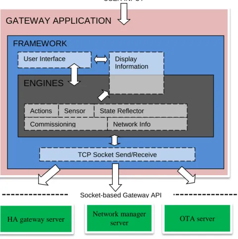
The figure below shows the main blocks of the sample application. USER INPUT
Fig 2. Sample Application High Level Block Diagram
The application connects to all 3 servers: Network Manager Server, Gateway Server and OTA Upgrade Server.
The Framework block manages connection and communication with the various servers. It sends out messages to the server over TCP socket connections and also receives messages from them. It also has a component that provides the UI for this application. Details on how to connect and send/receive messages to/from the various servers, and UI management can be found in the source code for this block.
The Framework block calls into the Engines block to service different requests from the User and/or Devices. Once the Framework block has identified which engine to call in response to a User action or response from a ZigBee device in the network, it calls the respective function inthe Engines block to act on it. Details regarding how to call an API from the application or how to interpret an incoming message from the Server can be found in the source code for this block.
6.2 Directory structure
Running the installer will also install the sample application sources and the corresponding build infrastructure at <INSTALL>/Source/Projects/zstack/linux/demo
HA gateway server Network manager server OTA server
GATEWAY APPLICATION
Socket-based Gateway API
FRAMEWORK
ENGINES
User Interface Display
Information
TCP Socket Send/Receive Actions Sensor
Commissioning Network Info State Reflector
9 Copyright © 2014 Texas Instruments, Inc. All rights reserved. (Please check User Guide Addendum for details on the installation).
Following is a brief look at the folders that constitute the sample application: ./framework
o User interface and other framework utilities required by the Demo Application ./engines
o Implementation of the various engines that call different Network Manager, Gateway Server, OTA Server APIs and process their responses.
./project
o main.c and makefile to build main.bin
6.3 Running the Sample Application
Please setup the board and install the pre-built binaries on it as per the instructions provided in the User Guide Addendum.
6.3.1 Starting the Application
Following are the steps to run the application on the target board once you have copied and untarred z-stack_linux_gateway_arm_binaries_<revision>.tar on itat <TARGET_INSTALL>
1. The sample application binary main.bin is in the <TARGET_INSTALL>/app/.
2. Ensure that libprotobuf-c.so.0 from the <TARGET_INSTALL>/protobuf/ is copied into /usr/lib/ on your target board.
3. Open two (or more) telnet sessions to the board
4. Enter the servers directory and run the zigbeeHAgw script. >cd ./servers/
>./zigbeeHAgw help
>./zigbeeHAgw <target board>
This script will start and monitor following servers:
NPI_lnx_xxx, ZLSZNP_xxx,
NWKMGR_SRVR_xxx, GATEWAY_SRVR_xxx OTA_SRVR_xxx
5. From a separate terminal, start the application using the following script: >cd ./servers
>./start_application
This script will start up the application and bring up the User Interface as shown in the following screen shot. Note that for maximum visibility, the window background should be dark (preferably black) and the window foreground shout be light (preferably white)
10 Copyright © 2014 Texas Instruments, Inc. All rights reserved.
6.3.2 User Interface
There are 8 different sections of the User Interface display. Below is a brief description of each. The back-single-quote ( `) can be used to move to Devices, Groups, or Scenes. The space can be used to move to the actions section.
1.
NETWORK
This section provides informative details of the network that has been created by the servers started by the zigbeeHAgw script. It indicates the External PAN ID (IEEE address of the Gateway device), the local PAN ID, channel number on which the network has been formed, and its current state for devices to join (open/close).
2.
DEVICES
This section provides details on the devices that are part of the network that has been created. At start-up, the only device listed, is the gateway device itself. The fields displayed include its unique IEEE address, network address (always 0x0 for the Coordinator), list of active endpoints, and some other details about the endpoint such as the Device ID and Profile ID that it is associated with (Home Automation i.e., HA). Device ID number is the one assigned by the specific profile specification (or defined by the user, in case of a manufacturer specific profile).
3.
GROUPS
Once you have devices added to the network you can create groups within them and that will allow you to send an “ACTION” (See section 5) to a group rather than to a single device. This section indicates which Group is active.
4.
SCENES
“Scenes” can be used to remember a set of states for a group of devices. For instance, if you have multiple lights in your network, you can change their settings individually or as a group, using the
11 Copyright © 2014 Texas Instruments, Inc. All rights reserved.
ACTIONS (see Section 5) keys. Once you do that, you can save these settings in a Scene, and recall them at will.
5.
ACTIONS
This provides a list of commands you can send targeting the network, or individual/group of devices. The commands include Light related settings (Off/On, Level, Hue, Saturation), Network related settings (Open the network for devices to join, remove devices from network, bind and/or unbind say a Switch to a Light etc), or Group/Scene commands.
6.
LOG
This section provides trace information that is generated from the application itself as it processes user-input, and also input from the servers.
7.
APPLICATION STATUS
This section provides information regarding the status of the application. The letters N, G and O in the title-bar refer to the 3 servers that this application is connected to (Network Manager, Gateway Manager and OTA Upgrade). Upper case indicates that the connection has been established and lower case indicates that it has been disconnected. The status log (Section 6) will indicate it when an application has established connection.
8.
HELP
This section provides Help. A more detailed Help Guide is available by pressing the “?” key.
6.3.3 Running the Application
In this section, we will walk through some of the features available in the sample application. Please use the Help Menu (“?” key) to learn about all of them.
6.3.3.1 Adding Devices
After you bring up the sample application and it has established connection to all the servers (“NGO” visible in the Application Status and Network Status indicates “ACTIVE”), the network is ready to accept
connections from ZigBee devices. In the “ACTIONS” section, use the spacebar to navigate to the “Permit Join” (shortcut key “P”) to open the network up for joining devices. You can change the time for which the network remains open by pressing +/- key. The “NETWORK” section will indicate a State of “OPEN” with a countdown timer.
At this point you can add other ZigBee devices to the network, by following the respective “Join” instructions in their documentation. Once a device has successfully joined the network, it will be listed in the “DEVICES” section along with all its details.
As already mentioned, Texas Instruments provides development kits to build an entire ZigBee network, such as (http://www.ti.com/tool/cc2530zdk-zll#buy). If you are using this kit, you can associate the lights by pressing the side button on the board for more than 5 seconds, initiating the so called classical commissioning procedure.
For more information on how to use this kit, please visit http://www.ti.com/tool/cc2530zdk-zll
12 Copyright © 2014 Texas Instruments, Inc. All rights reserved.
6.3.3.2 Light Control
In the “DEVICES” section, use the up/down arrow keys to navigate to a ‘Light’ device and use “ON/OFF” or “LVL/HUE/SAT” from the ACTIONS section to observe the Gateway control the ‘Light’ Device
6.3.3.3 Temperature/Humidity Sensor
Temperature/Humidity Sensors added to the network will register changes automatically and periodically when you press the “A” shortcut key.
6.3.3.4 Bind and Unbind.
The BIND/UNBIND (shortcut keys “D” and ”U”) action lets you bind and unbind one or more devices. For instance, to bind a Switch to a Light, you would follow the steps below:
In the “DEVICES” section, use the up/down arrow keys to navigate to the desired Switch device and press “D”. The trace log will confirm that a binding source has been selected.
(Pressing “D” again, will unselect your device).
Next navigate to a Light device and press “D” again. The trace log will confirm that a binding destination has been selected.
Trace log will show the messages that are being sent to initiate this bind, and also the final result (successful or unsuccessful). The entries should flash green to indicate that binding has been initiated.
After a successful bind, the switch should be able to control the Light.
o To Unbind, press “U” for the devices one by one, in the same order.
6.3.3.5 Groups
One or more devices (such as lights) can be added to a Group and then a command can be sent to them as a group.
As described in the help section (“?”), using the “`” key will let you navigate between the DEVICES, GROUPS and SCENES section. Switch to the GROUPS section, and use the arrow keys to select a particular group number.
Go back to the DEVICES section, and select (using the arrow keys) devices to add to the group, one at a time. Use the “G” shortcut key to add a device to a particular group.
Now you can switch these devices on and off as a group. Use the “`” key to navigate to the GROUPS section and then try any of the light related ACTIONS (OFF/ON, LVL, HUE, SAT etc) Also note that pressing the “b” key will toggle between the 3 transmission modes
(Unicast/Groupcast/Broadcast)
6.3.3.6 Scenes
Once a group has been created, you can set each device (individually or as a group) to a particular state and store that as a scene.
Create a Group (as described above) consisting of 1 or more devices.
Adjust the settings of each device to a desired value (for Light devices, use OFF/ON, LVL, HUE, SAT).
Use the “`” key to navigate to the SCENES section and pick a Scene #, then use the shortcut key “E” to store the scene
Change the settings of the device individually or as a group. Try and recall the scene using “C” either as a group (if in Groupcast transmission mode) or individually (if in Unicast transmission mode).6.3.3.7 OTA Upgrade
To initiate an “OTA Upgrade” you will need to do the following: Program up a SmartRF + CC2530 as an example OTA client.
13 Copyright © 2014 Texas Instruments, Inc. All rights reserved.
o An OTA Client hex is included as part of this release. You can use a Smart RF Flash Programmer to program it with this hex.
Add the OTA Client to the network.
Edit the existing “sample_app_ota.cfg” configuration file with following information:
<FULL PATH TO UPGRADE IMAGE > <NUM DEVIDES TO UPGRADE> < IEEE ADDR of DEVICE>
o An ota_sample_images/ folder has a couple of images that can be used to upgrade a SmartRF+CC2530 setup as an OTA client. Set the first field in sample_app_ota.cfg to the path of one of the files in this folder. You can find the IEEE address of the board is the first field in the DEVICES section of the Sample App UI. Use this value to replace the IEEE address in sample_app_ota.cfg.
o Please also refer to the Readme.txt included in the ota_sample_images/ folder. Press “O” to initiate the upgrade. The status log will show you a message when the upgrade is
done (typically takes several minutes to complete).
6.3.3.8 Other helpful features
There are several other “shortcuts”, details of which are provided in the Help menu.
As described in Section 6.2, you can change the channel or PAN ID for the network in the config.ini
file. However this file is only read once at start-up. To change either of these parameters, you can modify the config.ini file, and do a hard-reset by pressing the “X” (uppercase) shortcut key.
As described in Section 5.3, endpoints on the gateway can be defined using the gateway_config.tlg
file included with the sample application (as well as the Gateway server source code). Modify this file to create the endpoints required, and then do a soft reset by pressing the “x” shortcut key. This will allow the Gateway manager to come up again and this gateway_config.tlg file to be processed. Note:- Some endpoint numbers are reserved and must not be used as user-defined endpoint ids. Endpoint number 2 (Gateway endpoint) and 14 (OTA upgrade endpoint) are reserved
Endpoint 2 Simple Descriptor is defined as follows: Profile: HA
Device ID: Combined Interface Device Ver: 0 Flags: 0 Input Clusters: Basic Identify On Off IAS ACE Output Clusters: On Off Alarms Poll Control
Endpoint 14 Simple Descriptor is defined as follows: Profile: HA Device ID: 0 Device Ver: 0 Flags: 0 Input Clusters: OTA Output Clusters: NULL
14 Copyright © 2014 Texas Instruments, Inc. All rights reserved.
You could potentially bind a device in the network to a Gateway endpoint, and that would allow actions on this device to be reported to the gateway.
The sample application has a feature wherein you can store a ZCL over-the-air command as an application “macro”, and this macro can be associated with the Gateway endpoint. Here’s a quick set of steps to try it out:
o Uncomment the following lines in gateway_config.tlg: // endpoint { ID, EndpointDef, AttrDef }
endpoint { 3, OnOffLightEpDef, OnOffAttrList } endpoint { 4, OnOffLightEpDef, OnOffAttrList } endpoint { 5, OnOffLightEpDef, OnOffAttrList } endpoint { 6, OnOffLightEpDef, OnOffAttrList } endpoint { 7, OnOffLightEpDef, OnOffAttrList }
o Do a soft reset via shortcut key “x” (lower case). When the servers come back up, you should see the gateway device (first line in the DEVICES section) listed with these 5 new endpoints.
o Add a switch to your network (see section 7.3.3.1)
o Bind this switch to one of the endpoints in the device, say endpoint 3 (see section 7.3.3.4). Note that once you have selected a device using the UP/DOWN arrow keys, you can use the RIGHT/LEFT arrows keys to navigate between the endpoints. Every time you press the switch, you should see a message on the Status Log, confirming that the Gateway endpoint has received the message.
o Add a light device to the network.
o Now we will create/save a macro that switches this light on via a Gateway command
Navigate to the light device in the DEVICES list
Press the “[“ key to record the macro (you should see a “R” in the ACTIONS title bar to indicate that recording has commenced)
Press the “N” key to switch the light on
Press the “]” key to save the macro (you will see an “M” in the ACTIONS title bar to indicate a successful recording).
o Associate this macro with the switch, by pressing the switch. Now the macro has been associated with the Switch.
o Switch the light off using the gateway shortcut (“N”). Now you can switch it back on, by pressing the Switch.
You could also create a group and store a group ON/OFF command using the above example. The macro store/recall is a feature of the application. However, the creation and binding etc of custom endpoints on the gateway is a very important feature of the Z-Stack Linux Gateway. This feature allows us to associate one/more non-ZigBee actions with ZigBee device operation.
Several other shortcuts are available in the sample application. Here is an excerpt from the Help Menu:
Usage help start ---
- Either Devices, Groups or Scenes are selectable at a given time. [`] - toggle between the three selection modes (Devices/Groups/Scenes).
The section title of the current selection mode is highlighted with a brighter white, and marked with [].
- [UP/DOWN] - select a device,
[LEFT/RIGHT] - select an endpoint/group/scene - [SPACE] toggles between the available actions, [+/-] changes the value associated with the action, [ENTER] performs the selected action.
- Each action has a quick access key associated with it (underlined in the action name); Press a quick access key to select an action and perform it immidiately.
15 Copyright © 2014 Texas Instruments, Inc. All rights reserved.
- To issue a Bind/Unbind the action needs to be executed twice:
First it will select the binding source device. Second it will select the binding destination and perform the action.
if the selected binding destination is the same as the source, the operation is canceled. - Actions that requires destination address will use unicast, groupcast or broadcast addressing,depending on the current addressing mode (binding and device removal always use unicast)
- [A/a] - Automatically read data from all sensors periodically. - [x] - Perform a soft reset.
- [X] - Perform a hard reset.
- [K/k] - Shutdown the gateway subsystem. - [O/o] - Initiate OTA operation.
- [B/b] - Enable/Disable Broadcast addressing. (When enabled, 'B' appears on the actions title line.)
- [*] - Enable/Disable immediate execution. (When enabled, '*' appears on the actions title line.)
When immediate execution is enabled, actions will be triggered as soon as [+/-] is pressed, after the respective value is updated.
- [[] - Record a single-command macro - []] - Assign a a recorded macro - [1] - Display less log lines - [2] - Display more log lines
- [3] - Display less device lines, but more log lines
6.4 Rebuilding the Application
Although prebuilt binaries for the application are provided as part of this release, an end user might want to rebuild the sample application, say, after you add a new feature. The script required to rebuild the sample application on the Linux PC is included as part of this release. As described in Section 6.2, the sources for the sample app, are available at <INSTALL>/Source/Projects/zstack/linux/demo/project. Following are the steps to rebuild the sample application:
1. Make sure your PATH points to the correct toolchain for your compiler. For e.g,:
>export PATH=<SDK>/linux-devkit/sysroots/i686-arago-linux/usr/bin/:$PATH 2. Navigate to the following directory and launch the build script:
>cd <INSTALL>/Source/ >./build_sample_app >ls ./main.bin
You can tftp this rebuilt main.bin to the board, and copy it to this location: <TARGET_INSTALL>/app/. Startup the servers and application using the scripts as before (see Section 6.3.1).
7.
Serial Bootloader tool
The Serial Bootloader (SBL) tool as well as a configuration file specifically for your Gateway device are available as part of this release. Please refer to ‘Package Contents’ in the User Guide Addendum for the location of this tool and an example image that can be used to upgrade the image on your device.
Following are instructions on how to use the SBL tool to upgrade the firmware on your gateway device: 1. Once you have the SBL tool on your board at <TARGET_INSTALL>/tools/, first make sure no
servers are running.
2. Usage information is displayed if you run it as follows: >./sbl_tool.bin
16 Copyright © 2014 Texas Instruments, Inc. All rights reserved.
3. In general, it takes the name of the .bin file and the serial port (consult User Guide Addendum) as argument as shown below:
>./sbl_tool.bin ../misc/CC253x-GW-ZNP-<version>.bin <serial port>
8.
SOC Firmware Version tool
In order to retrieve the revision number information of the ZigBee SOC Firmware, a command line tool is provided as part of the package, under the tools directory.
This command line tool requires exclusive access to the serial port when communicating with the ZigBee SOC, so it can’t be run concurrently with any other server/tool that is using the same serial port.
To get the revision number, run the following command line from the Linux host (assuming current directory is tools):
>sw_rev=`./gw_soc_version_query.bin <serial port>| grep “Sofware Revision”|sed ‘s/Software Revision: //g’`
Following execution of the above line, sw_rev is a variable holding the revision number
Note: <serial port> will be specific to your platform reflecting the actual port through which the ZigBee SOC is connected.