Visualization of PLC Programs using XML
M. Bani Younis and G. Frey
Juniorprofessorship Agentenbased Automation University of Kaiserslautern
P. O. Box 3049, D-67653 Kaiserslautern, Germany Abstract− Due to the growing complexity of PLC programs
there is an increasing interest in the application of formal methods in this area. Formal methods allow rigid proving of system properties in verification and validation. One way to apply formal methods is to utilize a formal design approach in PLC programming. However, for existing software that has to be optimized, changed, or ported to new systems there is the need for an approach that can start from a given PLC pro-gram. Therefore, formalization of PLC programs is a topic of current research. The paper outlines a re-engineering ap-proach based on the formalization of PLC programs. The transformation into a vendor independent format and the visualization of the structure of PLC programs is identified as an important intermediate step in this process. It is shown how XML and corresponding technologies can be used for the formalization and visualization of an existing PLC program.
I. INTRODUCTION
Programmable Logic Controllers (PLCs) are a special type of computers that are used in industrial and safety-critical applications. The purpose of a PLC is to control a particular process, or a collection of processes, by produc-ing electrical control signals in response to electrical proc-ess-related inputs signals. The systems controlled by PLCs vary tremendously, with applications in manufacturing, chemical process control, machining, transportation, power distribution, and many other fields. Automation applica-tions can range in complexity from a simple panel to oper-ate the lights and motorized window shades in a conference room to completely automated manufacturing lines.
With the widening of their application horizon PLC pro-grams are being subject to increased complexity and high-quality demands especially for safety-critical applications. The growing complexity of the applications within the compliance of limited development time as well as the re-usability of existing software or PLC modules requires a formal approach to be developed [1]. Ensuring the high-quality demands requires verification and validation proce-dures as well as analysis and simulation of existing systems to be carried out [2]. One of the important fields for the formalization of PLC programs that have been growing up in recent time is Reverse-engineering [3]. Reverse Engi-neering is a process of evaluating something to understand how it works in order to duplicate or enhance it. While the reuse of PLC codes is being established as a tool for com-bating the complexity of PLC programs, Reverse Engineer-ing is supposed to receive increased importance in the com-ing years especially if exitcom-ing hardware has to be replaced by new hardware with different programming environ-ments.
Visualization of existing PLC programs is an important intermediate step of Reverse Engineering. The paper vides an approach towards the visualization of PLC pro-grams using XML which is an important approach for the orientation and better understanding for engineers working with PLC programs.
The paper is structured as follows. First, a short intro-duction to PLCs and the corresponding programming tech-niques according to the IEC 61131-3 standard is given. In Section III an approach for Re-engineering based on for-malization of PLC programs is introduced. The transforma-tion of the PLC code into a vendor independent format is identified as an important first step in this process. XML and corresponding technologies such as XSL and XSLT that can be used in this transformation are presented in Sec-tion IV. SecSec-tion V presents the applicaSec-tion of XML for the visualization of PLC programs and illustrates the approach with an example. The final Section summarizes the results and gives an outlook on future work in this ongoing pro-ject.
II. PLC AND IEC 61131
Since its inception in the early ‘70s the PLC received in-creasing attention due to its success in fulfilling the objec-tive of replacing hard-wired control equipments at ma-chines. Eventually it grew up as a distinct field of applica-tion, research and development, mainly for Control Engi-neering.
IEC 61131 is the first real endeavour to standardize PLC programming languages for industrial automation. In 1993 the International Electrotechnical Commission [4] pub-lished the IEC 61131 International Standard for Program-mable Controllers. Before the standardization PLC pro-gramming languages were being developed as proprietary programming languages usable to PLCs of a special ven-dor. But in order to enhance compatibility, openness and interoperability among different products as well as to promote the development of tools and methodologies with respect to a fixed set of notations the IEC 61131 standard evolved. The third part of this standard defines a suit of five programming languages:
Instruction List (IL) is a low-level textual language with
a structure similar to assembler. Originated in Europe IL is considered to be the PLC language in which all other IEC 61131-3 languages can be translated.
Ladder Diagram (LD) is a graphical language that has
its roots in the USA. LDs conform to a programming style Proceeding of the 2004 American Control Conference
borrowed from electronic and electrical circuits for imple-menting control logics.
Structured Text (ST) is a very powerful high-level
lan-guage. ST borrows its syntax from Pascal, augmenting it with some features from Ada. ST contains all the essential elements of a modern programming language.
Function Block Diagram (FBD) is a graphical language
and it is very common to the process industry. In this lan-guage controllers are modelled as signal and data flows through function blocks. FBD transforms textual program-ming into connecting function blocks and thus improves modularity and software reuse.
Sequential Function Chart (SFC) is a graphical
lan-guage. SFC elements are defined for structuring the organi-zation of programmable controller programs.
One problem with IEC 61131-3 is that there is no stan-dardized format for the project information in a PLC pro-gramming tool. At the moment there are only vendor spe-cific formats. This is also one reason for the restriction of formalization approaches to single programs or algorithms. However, recently the PLC users’ organization PLCopen (see http://www.plcopen.org) started a Technical Commit-tee to define an XML based format for projects according to IEC 61131-3. This new format will ease the access of formalization tools to all relevant information of a PLC project.
III. RE-ENGINEERING APPROACH
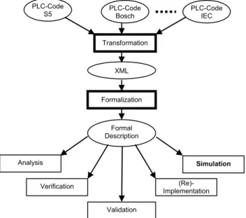
The presented approach towards re-engineering (cf. Fig. 1) is based upon the conception that XML can be used as a medium in which PLC codes will be transformed.
This transformation offers the advantage of obtaining a vendor independent specification code. (Even if the PLCo-pen succeeds in defining a standardized format for PLC applications, there will remain a lot of existing programs that do not conform to this standard.)
Fig. 1 Re-engineering approach
Based on this code a step-wise transformation to a for-mal model (automata) is planned. This model can then be used for analysis, simulation, formal verification and vali-dation, and finally for the re-implementation of the opti-mized algorithm on the same or another PLC.
Since re-engineering of complete programs will, in most cases, be only a semi-automatic process, intermediate visu-alization of the code is an important point. At different stages of the process different aspects of the code and/or formal model have to be visualized in a way that a designer can guide the further work. XML with its powerful visuali-zation and transformation tools is an ideal tool for solving this task.
IV. XML AS A TOOL FOR VISUALIZATION XML (eXtensible Markup Language) is a simple and flexible meta-language, i.e., a language for describing other languages. Tailored by the World Wide Web Consortium (W3C) as a dialect of SGML [5], XML removes two con-straints which were holding back Web developments [6]. The dependence on a single, inflexible document type (HTML) which was being much abused for tasks it was never designed for on one side; and the complexity of full SGML, whose syntax allows many powerful but hard-to-program options on the other side.
While HTML describes how data should be presented, XML describes the data itself. A number of industries and scientific disciplines—medical records and newspaper pub-lishing among them—are already using XML to exchange information across platforms and applications. XML can be tailored to describe virtually any kind of information in a form that the recipient of the information can use in a vari-ety of ways. It is specifically designed to support informa-tion exchange between systems that use fundamentally dif-ferent forms of data representation, as for example between CAD and scheduling applications.
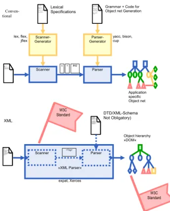
Using XML with its powerful parsers and inherent ro-bustness in terms of syntactic and semantic grammar is more advantageous than the conventional method of using a lexical analyzer and a validating parser (cf. Fig. 2, [7]).
The conventional method of analysis of program code requires a scanner (lexical analyser) which generates a set of terminal symbols (tokens) followed by a parser that checks the grammatical structure of the code and generates an object net. In the object net the internal structure of the program is represented by identified objects and the rela-tions between them. Both the scanner and the parser to be used in this method are document oriented which implies that analysis of different types of documents requires re-writing the generated code for the scanner and the parser. An example of an application of this method can be found in [8].
The most promising aspect of using XML instead is that XML and its complementary applications for transforma-tions are standardized so as to provide maximum flexibility to its user.
PLC-Code
Bosch PLC-CodeIEC
Transformation Formalization Validation Simulation (Re)-Implementation Analysis Verification XML PLC-Code S5 Formal Description
The XML based method is advantageous, since the lexi-cal specification is an invariant component of XML; there-fore the well-formedness is independent from the respec-tive individual application.
Fig. 2 Comparison between conventional and XML based method of lexi-cal analysis
Hence, an XML-Parser also can transfer well-shaped XML documents in an abstract representation called Docu-ment Object Model (DOM) without using a grammar. DOM is an application programming interface (API) for valid HTML and well-formed XML documents. It defines the logical structure of documents and the way a document is accessed and manipulated. In the DOM specification, the term “document” is used in a broad sense increasingly. XML is used as a way of representing many different kinds of information that may be stored in diverse systems, and much of this would traditionally be seen as data rather than as documents. Nevertheless, XML presents this data as documents, and the DOM can be used to manage this data [5].
XSLT, the transformation language for XML is capable of transforming XML not only to another XML or HTML but to many other user-friendly formats. Before the advent of XSLT, the transformation of XML to any other format was only possible through custom applications developed in a procedural language such as C++, Visual Basic or, Java. This procedure lacked the generality with respect to the structural variation of XML documents. Capitalizing on the concept that the custom applications for the transforma-tions are all very similar, XSLT evolved as a high-level declarative language [9].
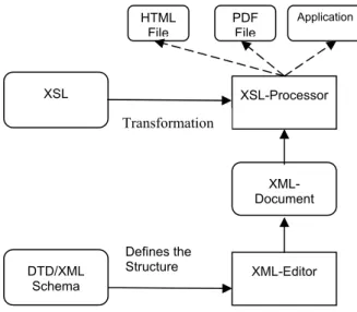
XSLT functions in two steps. In the first step, it per-forms a structural transformation so as to convert the XML into a structure that reflects the desired output. The second stage is formatting the new structure into the required for-mat, such as HTML or PDF (cf. Fig. 3 ). The most impor-tant advantage of this transformation is that it allows a sim-ple and easily-conceivable representation of the document or data structure embedded inside the well-structured but hard-to-understand XML to be produced. When HTML is chosen as the format of the transformed produce it is possi-ble to use the extensive ability of HTML to produce an easily-conceivable and attractive visualization of a pro-gram.
Fig. 3 Visualization of XML documents using XSL
Every XML document has its own syntax and vocabulary. Therefore, in addition to being well-formed, the XML document needs to conform to a set of rules. According to W3C recommendations this set of rules has to be defined either through a Document Type Definition (DTD) or an XML Schema. The rules defined in a DTD or an XML Schema state the hierarchical and structural constraints of the XML document.
The DTD is for defining the document grammars; more recently a number of alternative languages have been pro-posed. The W3C XML Schema language replicates the essential functionality of DTDs, and adds a number of fea-tures: the use of XML instance syntax rather than an ad hoc notation, clear relationships between schemas and name-spaces, a systematic distinction between element types and data types, and a single-inheritance form of type derivation. In other words schemas offer a richer and more powerful way of describing information than what is possible with DTDs. Fig. 4 shows the XML technologies discussed above and the connection between them.
V. AN APPROACH FOR THE VISUALIZATION OF PLC PROGRAMS
A. Overview
Since Instruction List (IL) is the most commonly used PLC language in Europe, the presented approach is based on this language. The proprietary IL dialect Siemens STEP 5 and the standardized version according to IEC 61131-3 are considered. XSL HTML XML DOM XML XSL-Processor sülz = 42; do [ süüüüüülz->foo; ] repeat while (what);
x = #42 Application specific Object net Parser- Generator Parser bra := b | br; süülz := s ü lz; brabra := bra { x = 42; } | bra bra bra { x = x + 42: } ; sülz := brabra | süülz;
yacc, bison, cup Grammar + Code for Object net Generation
Scanner- Generator Scanner TO_SEM = ‘;‘ TOK_b = ‘b‘ TOK_br = ‘br‘ TOK_INT = [0-9]* TOK_STRING = ‘“‘ .* ‘“‘ lex, flex, jflex Lexical Specifications W3C Standard W3C Standard »XML Parser« Scanner <Tag> Parser
expat, Xerces XML: <?xml versi <bla> <blubber>sülz</s <quassel/> <rabarber wdh=“ ojeojeoje ojemin </rabarber> </bla> Object hierarchy »DOM« <!ELEMEN <!ELEMENT b <!ATTLIST bar ba <!ELEMENT AT #PCDATA> <!ELEMENT PLT #PCDATA> DTD/XML-Schema Not Obligatory) Conven-tional
Fig. 4 Relation of XML to the corresponding technologies The generation of XML documents showing different aspects of a PLC program is realized in the following three steps (cf. Fig. 5):
1. Transformation of the PLC program to an XML document
2. Validation of the XML against the XML Schema which sets the syntax of the XML
3. Identification of the Instruction elements of the transformed XML according to the instruction set of the source PLC
These three steps are discussed in sub-sections B to D respectively. Sub-section E explains the visualization of the different XMLs obtained during the preceding steps.
Fig. 5 Conversion of PLC-program text to XML and validation Throughout this Section an example is used to illustrate the presented concepts. Fig. 6 shows a PLC code written in Instruction List Siemens S5. The PLC code is written in a
tabular form where each row element is either a delimited list consisting of address, label, instruction, operand and description or a comment.
Kommentar : Autor :
Erstellt :15.07.2003 Geaendert am: BIB:0 NETZWERK 1 EMPFANGEN SLAVE 3 VON MASTER NAME :EMPFMAST
0005 :U M98.7 ABFRAGE OB EMPFANG MOEGLICH
0006 :
0007 :SPB= M001
0008 :
0009 :A DB140 EMPFANGSFACH IST DB 140
000A :L KF+20 LAENGE DES DATENPAKETS
000C :T DL0
000D :L KF+0 ZIELNUMMER 0=MASTER
000F :T DR0
0010 :
0011 :UN M98.7 FANGEN WIEDER ERLAUBEN
0012 :S M98.7
0013 M001 :NOP 0 0014 :
0015 :BE BAUSTEIN ENDE
Fig. 6 A PLC program written in Siemens S5 Instruction List
B. Conversion of a PLC Program into a well-formed XML
Given a PLC program in ASCII format and in a tabular structure with separate columns for addresses, labels, in-structions, operands and descriptions delimited by white-spaces, XSLT can convert it into a well-formed XML document. The XML document obtained through this trans-formation is a hierarchically structured document.
Fig. 7 shows the XML document obtained through the transformation of the PLC code of Fig. 6. The XML docu-ment is structured in a hierarchy in which the root eledocu-ment is the ILCodeBlock representing the whole PLC code. Each of the rows of the PLC code is contained within a corre-sponding ILRow element which is further structured into child elements.
Note: The structure chosen for the XML representation of IL-Code is oriented at the working proposal of the PLCopen.
<?xml version="1.0" encoding="UTF-8"?> <ILCodeBlock xmlns="IL" xmlns:xsi="
http://www.w3.org/2001/XMLSchema-instance " xsi:schemaLocation=" http://www.eit.uni-kl.de/litz/aconml/ILns.xd name="Code"> <!--Kommentar :-->
<!--Autor :-->
<!--Erstellt :15.07.2003 Geaendert am: BIB:0--> <!--NETZWERK 1 EMPFANGEN SLAVE 3 VON MASTER--> <ILRow> <ILRowComment>NAME:EMPFMAST </ILRowComment> </ILRow> <ILRow> <Address>0005</Address> <Instruction>U</Instruction> <Operand>M 98.7</Operand> Text2XML XML XML Validation XML after Validation XML Schema Instruction Identification XSL HTML File PDF File Application XSL-Processor XML-Document XML-Editor DTD/XML Schema Defines the Structure XSL Transformation PLC- Program XML with Instruction ID
<Description>ABFRAGE OB EMPFANG MOEGLICH</Description> </ILRow> <ILRow> <Address>0007</Address> <Instruction>SPB=</Instruction> <Operand>M001</Operand> </ILRow> <ILRow> <Address>0009</Address> <Instruction>A</Instruction> <Operand>DB 140</Operand>
<Description>EMPFANGSFACH IST DB
140</Description>
</ILRow>
</ILCodeBlock>
Fig. 7 XML transform of the PLC program.
C. XML Validation against the XML Schema
The XML obtained as a result of the previous processing can be validated using a validating parser that confirms that the XML document in addition to being well-formed con-forms to the set of syntactic rules defined in context of the PLC programming language.
D. Identification of instructions
This step in the process of visualization of PLC pro-grams using XML ensures that the XML document to be used for visualization contains only valid instructions. XSLT can be used to transform the well-formed and valid XML to another XML which as a result of identification on instructions has an additional attribute appended to the in-struction tags. This attribute notifies whether the inin-struction is a valid instruction of the concerned instruction set. This transformation procedure is also capable of attaching at-tributes to the instruction tags that declares a classification of the instructions into predefined classes.
The instruction identification of the transformed XML proofs the semantic of the XML in accordance with the operation types of the PLC programming language.
In the example of this section, (cf. Fig. 8), the new XML contains additional attributes which classify the instructions according to the type of operation it represents. The STEP5 instructions are categorized into eleven different types of operations e.g. logical, jump, load or transfer operation, assignment, etc.
<?xml version="1.0" encoding="ISO-8859-1" ?> <ILCodeBlock>
<ILRow>
<Instruction instructionId="Logical
Opera-tion"> U</Instruction>
</ILRow>
<ILRow>
<Instruction instructionId="Jump Operation">
SPB=</Instruction>
</ILRow>
<Instruction instructionId=" Special
Opera-tion "> BE</Instruction>
</ILRow> </ILCodeBlock>
Fig. 8 A new transformed XML showing only the instructions and the corresponding instruction ID
E. Visualization of XML
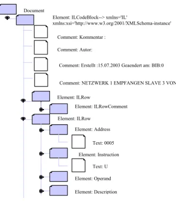
Both of the XML documents generated above can be transformed into HTML or other readable documents with the help of XSL. An ingenious XSL can be designed so as to produce an HTML which can convey the logical and other features of the PLC program in an easily conceivable form. Moreover, the DOM structure embedded in the XML (cf. Fig. 9), also enables the user to navigate through the PLC programs in an easy way.
Fig. 9 DOM tree of the XML
For the example the visualization is done in HTML. This visualization is done for the transformed XML after the validation of it’s syntax as a table where the child ele-ments of the ILRow are the columns of this table.
The XML after the instruction identification is trans-formed using the XSL, where the instruction and the in-struction Id, obtained after extracting the XML according to the type of operations are visualized in a table containing two columns (Instruction, Instruction Id) in HTML.
The HTML structures suggested here are not the only possibilities, with which the XML can be visualized, but they give a very easy practical option for the user’s grasp of the PLC code. Element: ILRow Element: ILRowComment Document Element: Operand Element: Instruction
Comment: Erstellt :15.07.2003 Geaendert am: BIB:0 Comment: NETZWERK 1 EMPFANGEN SLAVE 3 VON Comment: Kommentar : Comment: Autor: Element: ILRow Element: Address Text: 0005 Text: U Element: Description Element: ILCodeBlock--> xmlns='IL'
Fig. 10 shows the same PLC code as shown in Fig. 4 as a HTML document converted from the XML document shown in Fig. 7 using XSL. This visualization enables a better understanding of the PLC program. Fig. 11 shows the special visualization of instruction ids given in the XML of Fig. 6.
# Address Label Inst. Operand Description
1 NAME :EMPFMAST
2 0005 U M 98.7 EMPFANG MOEGLICHABFRAGE OB
3 0007 SPB= M001
4 0009 A DB 140 EMPFANGSFACH IST DB 140
5 000A L KF +20 DATENPAKETSLAENGE DES
6 000C T DL 0 7 000D L KF +0 ZIELNUMMER 0=MASTER 8 000F T DR 0 9 0011 UN M 98.7 EMPFANGEN WIEDER ERLAUBEN 10 0012 S M 98.7 11 0013 M001 NOP 0 12 0015 BE BAUSTEIN ENDE
Fig. 10 PLC program visualized in HTML VI. CONCLUSIONS AND OUTLOOK
Re-engineering of PLC programs needs a formal ap-proach to be developed. In this paper one way to solve this task is introduced. Based on a given PLC program written in Instruction List a step-wise transformation to a formal representation is proposed. Since this process will not be fully automatic, the need for flexible visualization of inter-mediate steps is derived. XML is presented as a flexible, standardized means to serve as data format for the descrip-tion of the PLC code. The corresponding technology of XSL transformations and the Document Object Model are presented as tools for the variety of customized visualiza-tion tasks during the re-engineering process.
Based on the XML description of PLC programs further transformations will be applied to finally derive a com-pletely formalized description of the original PLC code. This will be in the form of a finite automaton. During this process it is planned to identify common IL structures and formalize them via a library.
Gaining the Benefit of the XML Metadata Interchange (XMI) as an open industry standard that applies XML to abstract systems such as UML and referring to the classifi-cation of the instructions of IL into the eleven categories mentioned above. We can extract UML classes from this
classification, as it resembles the action semantics of UML.
Instruction Instruction_Id
U Logical Operation
SPB= Jump Operation
A Special Operation
L Load Transfer Operation T Load Transfer Operation L Load Transfer Operation T Load Transfer Operation
UN Logical Operation
S Assignment
NOP No Operation
BE Special Operation
Fig. 11 HTML of the XML with Instruction ID. VII. AKNOWLDGMENT
We would like to express gratitude to the “Stiftung Rheinland-Pfalz für Innovation” for sponsoring our work under project number 616.
VIII. REFERENCES
[1] L. Baresi, M. Mauri, A. Monti, and M. Pezze, “PLCTools: Design, Formal Validation, and Code Generation for Programmable Controllers”, in. IEEE Conference on Systems, Man, and Cybernetics
(SMC2000), Nashville, USA, Oct. 2000, pp.
2437-2442.
[2] G. Frey and L. Litz, “Formal methods in PLC pro-gramming”, in IEEE Conf. on Systems, Man and
Cy-bernetics (SMC'2000), Nashville, USA, Oct. 2000, pp.
2431-2436.
[3] M. Bani Younis and G. Frey, “Formalization of Exist-ing PLC Programs: A Survey.“, in CESA 2003, Lille (France), Paper No. S2-R-00-0239, July 2003.
[4] International Electrotechnical Commission, IEC In-ternational Standard 1131-3, Programmable
Control-lers, Part 3, Programming Languages, 1993.
[5] World Wide Web Consortium: http://www.w3.org/
[6] XML Home Page: http://xml.com/
[7] H. Albrecht and D. Meyer, “XML in der Automatisie-rungstechnik – Babylon des Informationsaustau-sches?“, at – Automatisierungstechnik 50 (2002) 2, R. Oldenbourg Verlag, München, pp 87-96.
[8] R. Kliewer, Reverse Engineering von Steuerungssoft-ware. Ph.D. thesis, University of Kaiserslautern, Ger-many, Institute for Production-Automation, 1999. [9] M. Kay, XSLT – Programmer’s Reference. ISBN