THE DIFFERENCE BETWEEN
COEFFICIENT-OF-FRICTION AND DRAG FACTOR
Mark George, Am SAE-A
Director, Accident Investigation Services Pty Ltd, Sydney, Australia.
May 2005 The terms coefficient-of-friction (µ) and drag factor (f) are expressions often used in crash investigation and are commonly associated with various vehicle speed calculations based upon tyre mark geometry. Accordingly, the definitions and application of the respective terms are accepted doctrine by the various international educational institutions associated with crash investigation.
Because the terms are closely related, their definitions and application are often confused by investigators and can result in misinterpretation, errors and confusion associated with vehicle speed calculations. This paper briefly discusses the specific scientific differences and applications between the two terms.
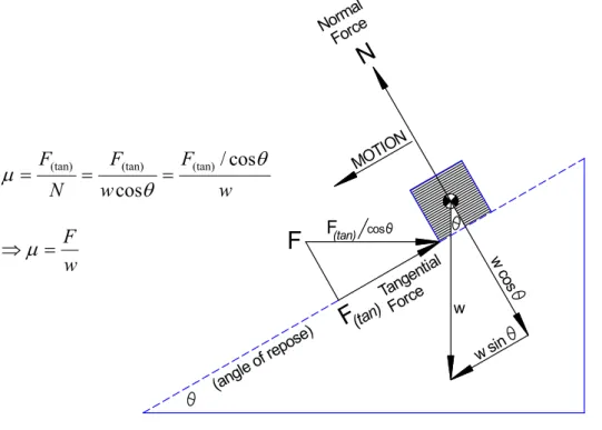
The coefficient-of-friction µ is defined as the ratio of the tangential force F(tan)
(parallel to the surface) applied to an object sliding across a surface to the normal force N (perpendicular to the surface) of an object.1
(tan)
F
F(tan) cosF
(angle o f repos e) Norma l Force w sin MOTION w c os Tange ntial Force wN
w F w F N F θ θ µ /cos cos (tan) (tan) (tan) = = = w F = ⇒µFigure 1. Graphical definition of µ.
From the above illustration, it can be seen that the relationship between F(tan) and N is
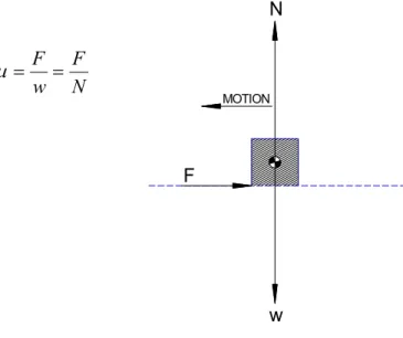
proportional to that of the horizontal force F and weight w. Thus, a simpler illustration is shown in Figure 2 for a level surface.
1 FRICKE L.B. (1990), The Traffic Accident Investigation Manual, Vol 2 – Traffic Accident Reconstruction, Northwestern University Traffic Institute, 1st Edition. Topic 862, Drag Factor
N MOTION w F N F w F = = µ
Figure 2. Simplified definition of µ.
Because opposing forces are equal in magnitude and opposite in direction (Newton’s 3rd law of motion), the coefficient-of-friction between two surfaces can be measured by pulling (or dragging) an object across a surface and resolving the forces. For convenience, figure 3 illustrates an object being pulled (with force F) across a level surface. N MOTION w F N F w F = = µ
Figure 3. Simple method of measuring µ
This basic concept is used in crash investigation to measure the coefficient-of-friction between vehicle tyres and road pavements and can be achieved in various ways. The most basic form of measurement is with a drag sled, where a weighted portion of a vehicle tyre is dragged across the road pavement in a controlled manner whereupon µ
is obtained by resolving the forces. If the surface is level, µ is obtained by dividing the horizontal force F required to drag the sled, by its weight w. i.e. if w = 10 kg and
F = 5 kg, then µ = 0.50. If the surface is not level there will be tangential forces to consider (i.e. less force is required to drag an object downhill and greater force for uphill), however, as illustrated in figures 1 and 2, resolving these forces will produce the same µ value as if the surface was level. This effectively means that µ between two surfaces does not alter with changes in gradient.
DRAG FACTOR
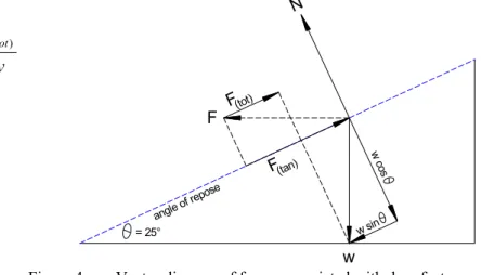
Drag Factor (f) is a non-dimensional (no units) number used to represent the acceleration or deceleration of a vehicle. It is defined as the total force F(tot) required
for a vehicle’s acceleration (or deceleration) in the direction of acceleration, divided by the vehicle’s weight. With reference to figure 4, the equation for f is expressed:
= 25° N w w c os w sin F angle of repose F(tot) (tan) F w F f = (tot)
Figure 4. Vector diagram of forces associated with drag factor and coefficient of friction.
It can be seen from figure 4 that the equation for f is similar to the simplified equation for µ, and hence the two definitions are often confused. However there is a distinct difference between the two. When measuring f and µ on a level surface, F(tot) = F
and w = N, which produces identical values for f and µ. As applicable to a vehicle speed from skid analysis, this means that f = µ only when a vehicle is skidding with all wheels locked on a level surface.
= 25° w w c os w sin F angle of repose = 25° N w c os w sin F angle of repose (tot) F (tan) F N w w = 30 kg F = 30 kg
Coefficient-of-Friction Drag Factor
(tan)
F
(tot)
F
It is common knowledge that it is easier to pull something down hill than uphill, and that downgrades make vehicle stopping distances longer than upgrades. Hence, for a skidding vehicle, f will reduce with a downgrade and increase for an upgrade, but µ
remains constant regardless of the grade. Consequently, investigating f and µ for a sloped surface will produce different values. It is important that investigators do not confuse these values and understand the differences. A comparative investigation is illustrated below. Figure 5.
0
.
1
2
.
27
2
.
27
(tan)=
=
=
N
F
µ
0
.
48
30
5
.
14
) (=
=
=
w
F
f
totIt is sometimes necessary to refer to published charts for estimating a range of µ for a given surface, i.e. dry/wet concrete, asphalt, gravel, snow, ice etc. If this information is to be applied to a sloped roadway, then a range for f needs to be investigated. If the case in question involves a speed from skid analysis, then f can be provisionally solved if the grade is known, but will only be relevant if the vehicle is skidding with
all wheels locked. If not all wheels are locked, further investigations are necessary to solve for the vehicle’s resultant drag factor fR.
RESULTANT DRAG FACTOR - fR
During harsh braking, a car experiences forward load shift, increasing the load on its front axle and reducing the load proportionally on its rear axle. If all wheels are locked during the skid, as discussed earlier the vehicle’s deceleration will equal µ and
f if the surface is level, or just f if on a sloped surface. If not all wheels lock during the skid, particularly on an axle group, it cannot be assumed that the vehicle has decelerated with a drag factorequal to locked wheel conditions.
Where a vehicle has unequal axle drag factors, the vehicle’s resultant drag factor fR is
expressed: ) ( 1 ) ( r f r f f f R f f z f f x f f − − − − =
where: fR = resultant vehicle drag factor
ff = drag factor on front axle
fr = drag factor on rear axle
xf = horizontal distance of the centre of mass from the
front axle as a decimal fraction of wheelbase
z = height of the centre of mass as a decimal fraction
of the wheelbase.
Analysis of unequal axle drag factors on a vehicle therefore requires a more detailed investigation of the subject vehicle’s mass and careful consideration of the variables in question.
CONCLUSION
The coefficient-of-friction µ between two surfaces does not alter with changes in gradient.
Drag Factor f changes proportionally to the gradient.
As applicable to crash investigation, f = µ only when a vehicle is skidding with all wheels locked on a level surface.
REFERENCES
1. FRICKE L.B. (1990), The Traffic Accident Investigation Manual, Vol 2 – Traffic Accident Reconstruction, Northwestern University Traffic Institute, 1st Edition.
2. Britannica Macropaedia Vol. 23, Edition 15, 1992 – Mechanics.
ACKNOWLEDGEMENTS
George Bonnett JD, Reconstruction Technology, Rockledge, FL USA for peer review of the article.
AUTHOR
Mark H. George Am SAE-A Director/Principal Investigator
Accident Investigation Services Pty Ltd P.O. Box 695, Kingswood NSW Australia Tel: +61 2 47364736
www.accidentinvestigation.com.au [email protected]