Device-to-Device Communication and Multihop
Transmission for Future Cellular Networks
Ahmed Mohammed Amate
A thesis submitted to the University of Hertfordshire in partial
fulfilment of the requirements for the degree of Doctor of philosophy
ABSTRACT
The next generation wireless networks i.e. 5G aim to provide multi-Gbps data traffic, in order to satisfy the increasing demand for high-definition video, among other high data rate services, as well as the exponential growth in mobile subscribers. To achieve this dramatic increase in data rates, current research is focused on improving the capacity of current 4G network standards, based on Long Term Evolution (LTE), before radical changes are exploited which could include acquiring additional/new spectrum. The LTE network has a reuse factor of one; hence neighbouring cells/sectors use the same spectrum, therefore making the cell edge users vulnerable to inter-cell interference. In addition, wireless transmission is commonly hindered by fading and pathloss.
In this direction, this thesis focuses on improving the performance of cell edge users in LTE and LTE-Advanced (LTE-A) networks by initially implementing a new Coordinated Multi-Point (CoMP) algorithm to mitigate cell edge user interference. Subsequently Device-to-Device (D2D) communication is investigated as the enabling technology for maximising Resource Block (RB) utilisation in current 4G and emerging 5G networks. It is demonstrated that the application, as an extension to the above, of novel power control algorithms, to reduce the required D2D TX power, and multihop transmission for relaying D2D traffic, can further enhance network performance. To be able to develop the aforementioned technologies and evaluate the performance of new algorithms in emerging network scenarios, a beyond-the-state-of-the-art LTE system-level simulator (SLS) was implemented. The new simulator includes Multiple-Input Multiple-Output (MIMO) antenna functionalities, comprehensive channel models (such as Wireless World initiative New Radio II i.e. WINNER II) and adaptive modulation
and coding schemes to accurately emulate the LTE and LTE-A network standards. Additionally, a novel interference modelling scheme using the ‘wrap around’ technique was proposed and implemented that maintained the topology of flat surfaced maps, allowing for use with cell planning tools while obtaining accurate and timely results in the SLS compared to the few existing platforms.
For the proposed CoMP algorithm, the adaptive beamforming technique was employed to reduce interference on the cell edge UEs by applying Coordinated Scheduling (CoSH) between cooperating cells. Simulation results show up to 2-fold improvement in terms of throughput, and also shows SINR gain for the cell edge UEs in the cooperating cells. Furthermore, D2D communication underlaying the LTE network (and future generation of wireless networks) was investigated. The technology exploits the proximity of users in a network to achieve higher data rates with maximum RB utilisation (as the technology reuses the cellular RB simultaneously), while taking some load off the Evolved Node B (eNB) i.e. by direct communication between User Equipment (UE). Simulation results show that the proximity and transmission power of D2D transmission yields high performance gains for a D2D receiver, which was demonstrated to be better than that of cellular UEs with better channel conditions or in close proximity to the eNB in the network. The impact of interference from the simultaneous transmission however impedes the achievable data rates of cellular UEs in the network, especially at the cell edge. Thus, a power control algorithm was proposed to mitigate the impact of interference in the hybrid network (network consisting of both cellular and D2D UEs). It was implemented by setting a minimum SINR threshold so that the cellular UEs achieve a minimum performance, and equally a maximum SINR threshold to establish fairness for the D2D transmission as well. Simulation results show
an increase in the cell edge throughput and notable improvement in the overall SINR distribution of UEs in the hybrid network. Additionally, multihop transmission for D2D UEs was investigated in the hybrid network: traditionally, the scheme is implemented to relay cellular traffic in a homogenous network. Contrary to most current studies where D2D UEs are employed to relay cellular traffic, the use of idle nodes to relay D2D traffic was implemented uniquely in this thesis. Simulation results show improvement in D2D receiver throughput with multihop transmission, which was significantly better than that of the same UEs performance with equivalent distance between the D2D pair when using single hop transmission.
ACKNOWLEDGEMENTS
My sincere gratitude goes to my principal supervisor Dr. Pandelis Kourtessis for his relentless guidance and continuous motivation, and also to my second supervisor Prof. John M. Senior for his professionalism and support during the course of my research. I would also like to thank Dr. Milos Milosavljevic and Dr Stratis Sofianos who were not only excellent mentors during my research but are also good friends. My appreciation goes to my friends, colleagues in the Optical Network research group, and also the Radio and Mobile Communication group who have provided a friendly atmosphere during my time of study. I will like to acknowledge the Petroleum Trust Development Fund (PTDF) for funding my expenses for most of my research period.
I cannot express enough gratitude to my parents, siblings and family friends for the love, affection and support of all sorts they have given me all my life and especially during my programme. I will like to thank my lovely wife and children for giving me the extra motivation and support I needed in achieving my goals. And last but not the least; I will like to thank Almighty Allah for providing me with the grace, tolerance and the ability to see through my programme and for my life achievements in general.
TABLE OF CONTENTS
ABSTRACT ... i
ACKNOWLEDGEMENTS ... iv
TABLE OF CONTENTS ... v
LIST OF FIGURES ... ix
LIST OF TABLES ... xiii
GLOSSARY ... xiv
DECLARATION ... xviii
C
hapter 1:
1. Introduction ... 11.1 Mobile communication ... 1
1.1.1 Network performance and limitations of the 4G LTE network ... 3
1.2 Worldwide deployment of LTE networks ... 5
1.3 Advances to 5G network implementation ... 7
1.3.1 Projected technologies and architectures to enhance spectrum utilisation for future networks ... 8
1.4 Research motivation ... 10
1.5 Research contribution ... 12
1.6 Thesis outline ... 14
C
hapter 2:
2. Towards Providing Multi-Gigabits Data Rate Traffic for Future Cellular Networks 15 2.1 Introduction ... 152.2 Evolution of cellular networks to the current 4G standards ... 16
2.3 The 4G LTE network architecture ... 20
2.3.1 Network implementation of the 4G LTE standard ... 21
2.4 Enhancements in the LTE-Advanced networks ... 24
2.4.1 Coordinated multipoint ... 26
2.5 Efficient spectrum utilisation with maximum use of cellular resources in future networks ... 28
2.5.1 Cognitive radio ... 29
2.5.2 Device-to-Device communication ... 32
2.5.3 Multihop communication in cellular networks ... 35
2.6 Architectural developments and research initiatives for multi-gigabit data rates in future networks ... 37
2.7 Summary ... 42
C
hapter 3:
3. System-Level Design and Evaluation of LTE Simulator Platform ... 463.1 Introduction ... 46
3.2 Link-level to system-level modelling ... 47
3.2.1 Link quality measurement in SLS model ... 52
3.3 Network architecture and channel modelling ... 54
3.3.1 SLS parameters and Simulation methodology... 57
3.3.2 Channel modelling ... 60
3.3.3 WINNER channel model ... 62
3.4 The LTE transmission modes ... 64
3.5.1 Evaluation of the common scheduling algorithms in the LTE network ... 73
3.6 Analysis of cell edge UE performance in LTE networks ... 76
3.7 Novel enhancement to existing state-of-the-art LTE SLS ... 80
3.8 Summary ... 83
C
hapter 4:
4. Inter-Cell/Site Interference Modelling and CoMP for 4G and Beyond Networks . 87 4.1 Introduction ... 874.2 Challenges in 4G+ networks simulation platforms... 89
4.2.1 Traditional wrap-around modelling implementation ... 90
4.3 Efficient interference modelling for 4G+ networks ... 91
4.3.1 Performance evaluation of proposed interference modelling ... 94
4.4 Inter-cell coordination in LTE-A networks ... 102
4.4.1 Beamforming ... 103
4.5 CoMP algorithm based on UE location ... 104
4.5.1 Performance enhancement with proposed CoMP algorithm ... 111
4.6 Summary ... 113
C
hapter 5:
5. Device-to-Device Communication and Multihop Transmission for Future Cellular Networks ... 1165.1 Introduction ... 116
5.2 Modelling of D2D UE in SLS ... 118
5.3 Performance gains of D2D communication underlaying the LTE network .. 123
5.5 Proposed power control algorithm with power reduction ... 131
5.5.1 Performance evaluation of proposed power control algorithm ... 133
5.6 Multihop transmission for relaying D2D traffic ... 138
5.6.1 Performance evaluation of the MH transmission scheme ... 141
5.7 Summary ... 146
C
hapter 6:
6. Research Summary and Future Work ... 1486.1 Introduction ... 148
6.2 Research drive ... 149
6.3 Thesis summary and outcomes ... 152
6.4 Future directions ... 156
6.4.1 Efficiency in implementing CoMP schemes ... 157
6.4.2 Enhanced investigation scenarios and implementation for D2D communication ... 159
REFERENCES ... 166
Appendix A ... 189
LIST OF FIGURES
Figure 1-1 Estimation of active mobile subscribers from 2011 to 2014 [3] ... 1
Figure 1-2 Projection of mobile data traffic from 2008 to 2016 [6] ... 2
Figure 1-3 LTE deployment plans and strategies between 2012-2015 [26] ... 6
Figure 1-4 Range expansion with heterogeneous cellular implementation [31] ... 8
Figure 2-1 Overview of cellular network generations and data growth [39, 40] ... 16
Figure 2-2 Evolution of broadband wireless technologies with 3G networks [49] ... 19
Figure 2-3 A comprehensive LTE network architecture ... 21
Figure 2-4 TDD and FDD frame structures of the LTE network [9] ... 22
Figure 2-5 Resource grid structure of the LTE network [51] ... 23
Figure 2-6 Classification of the CoMP schemes [54] ... 27
Figure 2-7 Illustration of the radio frequency spectrum ... 28
Figure 2-8 Illustration of network assisted D2D communication in a single cell ... 32
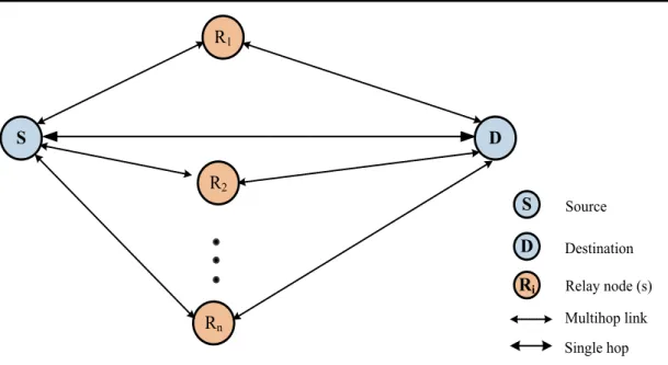
Figure 2-9 A general description of MH communication with two-hop relay between source and destination nodes ... 36
Figure 2-10 Consolidation of technologies for future 5G cellular architecture [89] ... 40
Figure 2-11 RAT selection by devices in future 5G networks [90] ... 41
Figure 2-12 Self-interference cancellation architecture [97] ... 42
Figure 3-1 General layers for simulator modelling [101] ... 48
Figure 3-2 Link-system level modelling of the LTE network SLS [103] ... 49
Figure 3-3 SNR to CQI mapping ... 51
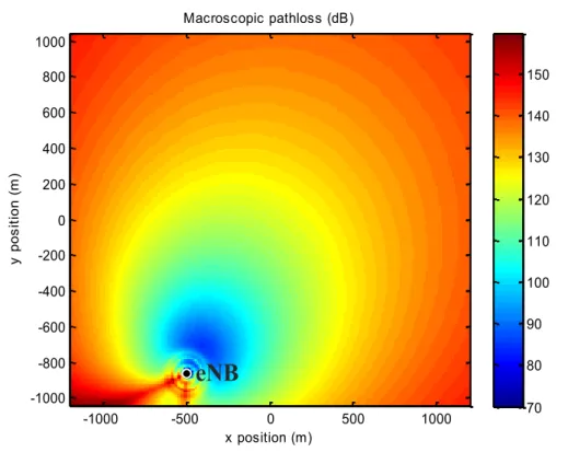
Figure 3-4 Macroscopic pathloss for an eNB with 30 degrees azimuth in a ROI ... 53
Figure 3-5 Correlated shadow fading map for multiple eNB sites ... 54
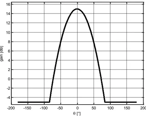
Figure 3-7 Antenna gain pattern for the individual sectors in SLS ... 56
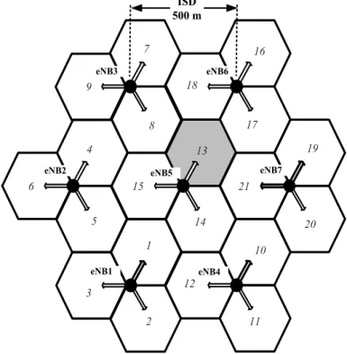
Figure 3-8 Cell-layout for the performance investigation, indicating the sector where simulation results were obtained ... 68
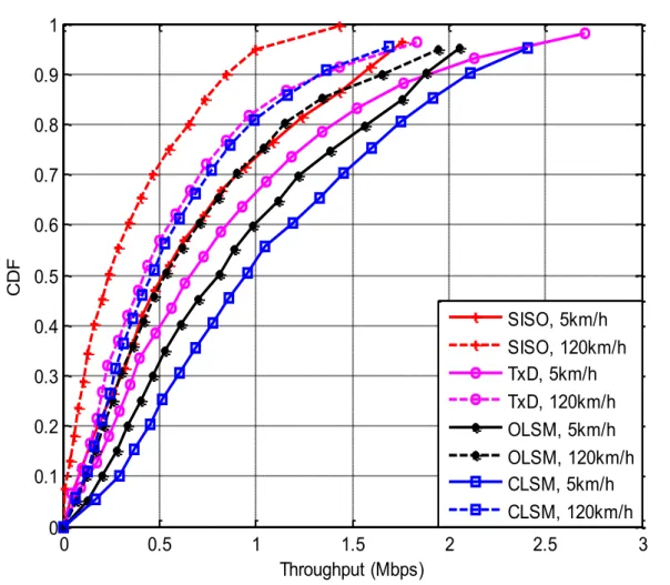
Figure 3-9 CDF of UE throughput in an LTE network with different UE speed for the SISO, TxD, OLSM and CLSM transmission modes ... 70
Figure 3-10 Throughput CDF with different schedulers for UEs in target sector ... 74
Figure 3-11 Cell layout showing the different sites surrounding the target sector ... 77
Figure 3-12 UE throughput for a 5 MHz bandwidth channel ... 78
Figure 3-13 UE throughput for a 10 MHz bandwidth channel ... 78
Figure 3-14 UE throughput for a 20 MHz bandwidth channel ... 79
Figure 4-1 Typical SLS topology comprising two tiers, 19 sites and 57 sectors ... 89
Figure 4-2 Illustration of a typical WA implementation [135] ... 91
Figure 4-3 Proposed cell layout with VeNBs and quadrant in the ROI ... 92
Figure 4-4 Boxplot showing the SINR of UEs in the investigated sectors ... 97
Figure 4-5 CDF of sector 2 with WA and without WA ... 98
Figure 4-6 CDF of sector 5 with WA and without WA compared to sector 13 ... 99
Figure 4-7 SE of the evaluated sites/sectors using RR and PF schedulers ... 100
Figure 4-8 Illustration of Antenna beams steered to different directions ... 104
Figure 4-9 Illustration of cooperating cells and “conflicting border” ... 105
Figure 4-10 Illustration of fixed beams for non-adaptive antennas in SLS with UEs served by different cells at a common border ... 109
Figure 4-11 Illustration of beam directions at 1st time slot ... 109
Figure 4-12 Illustration of beam directions at 2nd time slot ... 110
Figure 4-13 UE goodput CDF with and without inter-cell coordination ... 112
Figure 5-1 Cell layout with UEs in both cellular and D2D mode in target sector ... 118
Figure 5-2 Pathloss and antenna pattern of D2D TX and target sector eNB ... 120
Figure 5-3 Pseudo code summarising mode selection in the devised SLS model ... 122
Figure 5-4 Mean goodput of D2D RX with increasing D2D TX power and distance between the D2D pair ... 125
Figure 5-5 Mean goodput for cellular and D2D UEs in target sector ... 126
Figure 5-6 CDF of UEs goodput distribution with and without D2D transmission .... 127
Figure 5-7 Illustration of D2D interference in a single cell using the DL resources ... 129
Figure 5-8 Procedure of the proposed power control algorithm ... 131
Figure 5-9 SINR distribution of the D2D RX with and without power control ... 134
Figure 5-10 SINR distribution of the cellular UEs in the target sector ... 135
Figure 5-11 SINR distribution of both cellular and D2D UEs in target sector ... 136
Figure 5-12 Goodput of target sector UEs with and without power control scheme .. 137
Figure 5-13 Illustration of MH D2D transmission set-up ... 140
Figure 5-14 Goodput distribution with increasing distance between the D2D transceiver ... 142
Figure 5-15 Mean goodput of the D2D RX with increasing distance between the D2D pair ... 143
Figure 5-16 D2D RX SINR with increasing distance from the D2D pair ... 144
Figure 5-17 Target sector UEs goodput with SH and MH D2D transmission ... 145
Figure 6-1 CAPEX and OPEX analysis for a site [168] ... 158
Figure 6-2 High level representation of CRAN architecture [168] ... 159
Figure 6-3 Illustration of interference in a multi-cell scenario with multiple D2D pairs supported by a CRAN architecture ... 161
Figure A-1 Description of Azimuth angle on a ground plane ... 189
Figure A-2 Azimuth angle for the different sectors belonging to an eNB site ... 190
Figure A-3 A portion on the ROI map showing pixel positions ... 190
Figure B-1 Illustration of the cell layout highlighting the quadrants in the ROI ... 193
Figure B-2 Flow chart describing conditions for UE relocation algorithm in quasi quadrants of the ROI ... 194
LIST OF TABLES
Table 2-1 Number of available RBs for different LTE bandwidths (DL) [51] ... 24
Table 2-2 IMT-A requirement and LTE-A projected capability [53] ... 25
Table 2-3 SE comparison for LTE release 8 with LTE-A targets [52] ... 26
Table 3-1 Summary of SLS parameters ... 58
Table 3-2 Pseudo code describing the flow of functionalities in SLS model ... 59
Table 3-3 Description of some major enhancements to the existing SLS ... 81
Table 4-1 A detailed summary of simulation parameters ... 95
Table 4-2 Simulation efficiency for SLS with and without WA ... 101
Table 4-3 Detailed description of the CoMP algorithm implementation ... 107
Table 5-1 D2D and cellular UEs parameters in SLS model ... 120
Table 5-2 Conditions for D2D TX power reduction in power control algorithm ... 133
Table A-1 Overview of CQI index and corresponding values [106] ... 191
Table A-2U and Di matrices for different number of antennas [126] ... 192
GLOSSARY
1G First generation
2G Second generation
3G Third generation
3GPP 3rd Generation partnership project
4G Fourth generation
5G Fifth generation
AWGN Additive white Gaussian noise
BBU Baseband unit
BLER Block error rate
BS Base station
CAPEX Capital expenditure
CDF Cumulative distribution function
CDMA Code division multiple access
CLSM Closed loop spatial multiplexing
CoBF Coordinated beamforming
CoMP Coordinated multipoint
CoSH Coordinated scheduling
CP Cyclic prefix
CR Cognitive radio
CRAN Cloud/Centralised radio access network
CSI Channel state information
CQI Channel quality index
DL Downlink
eNB Evolved node b
EDGE Enhanced data rate for GSM evolution
EU European-union
EPC Evolved packet core
FDD Frequency division duplex
GPRS General packet radio services
GPS Global positioning system
GSM Global system for mobile
HDTV High-definition television
HetNet Heterogeneous network
HSPA High speed packet access
IMT-A International mobile telecommunications-Advance
IP Internet protocol
ISD Inter-site distance
ISM Industrial, scientific and medical
ITU International telecommunication union
JP Joint processing
kbps kilobits per second
LTE Long term evolution
LPM Link performance model
LQM Link quality model
LTE-A Long term evolution-Advanced
MAC Medium access control
MCS Modulation and coding scheme
MHz Mega Hertz
MH Multihop
MIMO Multiple-input multiple-output
OFDM Orthogonal frequency-division multiplexing
OFDMA Orthogonal frequency-division multiple access
OLSM Open loop spatial multiplexing
PF Proportional fair
OPEX Operational expenditure
PAPR Peak to average power ratio
QoS Quality of service
RB Resource block
RAN Radio access network
RAT Radio access technology
ROI Region of interest
RNC Radio network controller
RR Round robin
RS Reference signal
RX Receiver
SE Spectral efficiency
SH Single hop
SISO Single-input single-output
SLS System-level simulator
SMS Short message service
SINR Signal to interference noise ratio
SNR Signal to noise ratio
SC-FDMA Single carrierfrequency-division multiple access
TDD Time division duplex
TTI Transmission time interval
TB Transport block
TxD Transmit diversity
TX Transmitter
UE User equipment
UL Uplink
UMTS Universal terrestrial mobile system
VeNBs Virtual eNBs
WA Wrap around
WiFi Wireless fidelity
WiMAX Worldwide interoperability for microwave access
WINNER Wireless world initiative new radio
WLAN Wireless local area network
WMAN Wireless metropolitan area network
WPAN Wireless personal area network
DECLARATION
The following papers are either under review or already published, and parts of the materials are included in this thesis:
A. Amate, S. Sofianos, M. Milosavljevic, P. Kourtessis, and J. M. Senior, "An efficient inter-site interference model for 4G wireless networks," in 2013 IEEE International Conference on Communications (ICC), 2013, pp. 5355-5359.
A. Amate, M. Milosavljevic, P. Kourtessis, M. Robinson, J. M. Senior, “SDN based millimeter wave Radio over Fiber (RoF) network” 2015 SPIE photonics WEST, the laser, photonics, Biomedical Optics Conference.
A. Amate, M. Milosavljevic, P. Kourtessis, and J. M. Senior, “Interference mitigation using power control in LTE-A networks overlaying D2D communication” submitted to IEEE transaction on communication.
C
hapter 1
1.
Introduction
1.1
Mobile communication
The growth of wireless networks in general as complementary to the wireline alternatives (e.g. optical networks [1]) has continuously amplified: mainly due to the cost-effective terminals, increasing data rates and ubiquity provided by the wireless networks [1]. This has led to constant advances in mobile communication from the initial provision of analogue voice services to the present state-of-the-art technologies, which are expected to support future 3-play services with multi-channel HDTV, 3D TV, and other high capacity services that generate overwhelming traffic [2]. These services include multi-player online gaming, cloud computing, remote application hosting, social networking and home management services (i.e. video surveillance). Figure 1-1 illustrates an estimate of active mobile subscribers worldwide from 2011 to 2014 [3].
The International Telecommunications Union (ITU) provided the statistic in May 2014, showing the increasing number of active mobile subscribers worldwide till present. It shows almost 7 Billion mobile subscribers in 2014, equivalent to about 95 percent of the world population. In more detail, it indicates up to 5.9 Billion active subscribers in 2011, with an estimated growth of over a billion users worldwide through to 2014. Consequently, there has been increasing demand for provision of broadband on the go to offer bandwidth-demanding services such as HD real-time multimedia and other high data rate services as earlier mentioned by the growing subscribers of the networks [4, 5]. A study presented by Ericsson in Figure 1-2 [6] shows a projection of mobile data traffic for voice and data, through 2016, which was based on measurements from live networks of the company over several years up to 2011. The forecast in the graph shows over 10-fold increase in the projected period, with more requirements on mobile data usage (using smart phones and tablets) compared to voice services: over 4500 Petabytes (1015 bytes) of mobile data utilisation with PCs/tablets by 2016. This type of prognostications has compelled the need for continuous research in developing capable infrastructure for providing the required services to the ever-increasing subscribers to the network.
Mobile communication has evolved through various generations of wireless network standards with improvements in coverage area, data rate provision etc. to the current 4G networks. The 3GPP [7] and Institute of Electrical and Electronics Engineers (IEEE) [8] have been actively involved in developing and/or advancing the network technologies for the cellular and broadband access networks respectively. Examples of some prevalent technologies by these organisations include the Long Term Evolution (LTE) [9] and IEEE 802.11 standards (also referred to as WiFi) [10]. The 3GPPs LTE network is presently dominating the Wireless Wide Area Network (WWAN) market over competing 4G technologies with exponential increase in the network’s deployment worldwide since the last quarter of 2009 [9]. While 4G networks deployment is ongoing, active research is conducted alongside to determine solutions for the next generation of cellular networks (i.e. 5G). The research initiatives are spearheaded by the European Union (EU) through the recently finished FP7 and current Horizon-2020 research frameworks, with relevant projects including METIS-2020, 5GNOW, COMBO, MiWaves, and MiWEBA [11-16]. These projects are also in collaboration with major telecoms companies such as Alcatel Lucent, Ericsson, and Huawei. Some key measures commonly considered in the aforementioned projects include improved network architectures and protocols, and complimentary/add-on technologies to the existing networks, in order to achieve the data rates requirement of the increasing subscribers for the current and future networks such as LTE-Adanced networks.
1.1.1 Network performance and limitations of the 4G LTE network
The initial release of the LTE standard was presented commercially as a 4G network along with other similar technologies [17]. The LTE network was however more auspicious as it has a flat architecture, leading to lower latency, better throughput, andhigh-quality user experience even with the initial release (release 8): with theoretical throughput of up to 300 Mbps and 75 Mbps for the Downlink (DL) and Uplink (UL) respectively for LTE release 9 [18]. The network is implemented using current technologies such Orthogonal Frequency-Division Multiple Access (OFDMA, for the DL) [19] and Multiple-Input Multiple-Output (MIMO) [20] in order to achieve the specified data rates improvement. Additionally, the UL is based on the Single-Carrier Frequency Division Multiplexing Access (SC-FDMA) scheme [21]. Hence there is more energy efficiency from the User Equipment (UE) processing power requirement perspective, as the SC-FDMA transmission scheme has a low peak to average power ratio (PAPR).
The network is deployed with a universal reuse factor (frequency reuse of 1), which increases the efficiency in the spectrum utilisation of the network. Despite the advantage of the universal reuse factor, it however causes high inter-cell interference, since all the cells use the same spectrum, especially for users at the cell edge. Consequently, 3GPP introduced Coordinated Multipoint (CoMP) scheme [22] to improve the spectral efficiency for cell edge users in the initial and future releases of the LTE network standards. The scheme involves coordination between network entities such as base stations, referred to Evolved Node B (eNB) in LTE networks, and UEs of different cells/sites in order to achieve this improvement [22]. The initial release however fell short on the ITU’s definition of International Mobile Telecommunications-Advanced (IMT-A), to provide up to 1 Gbps throughput as the ultimate goal for 4G networks. This was then fulfilled in the latest release (i.e. release 10) referred to as LTE-Advanced (LTE-A) [23] as a true 4G network. The LTE-A is specified to provide up to 1 Gbps throughput DL and 500 Mbps UL theoretically with an aggregate of 100 MHz radio channels. Furthermore, the current release is
backward compatible with the initial releases (LTE releases 8 and 9) and previous 3G networks, hence provides seamless/cheaper migration to the network [23].
One of the main performance limitations of the 4G LTE network is in the cell edge performance degradation. Another example of these limitations is the capabilities of the transceiver terminals relative to the specified requirement to achieve LTE performance, e.g. multiple antenna user terminals. The cell edge performance degradation is caused mainly due to the tight reuse factor of the network, and limitations of the wireless propagation medium itself. One example of such limitation is ‘multi-path fading’, where obstacles in the surrounding environment (which vary from hills, buildings, etc.) attenuate the propagated signal, hence, leading to flawed detection of the received signal [24]. Another major issue with the wireless communication in general is the scarcity of radio spectrum (which is finite and expensive) and inefficiency in the spectrum usage. These factors amongst other challenges limit the wireless networks (such as LTE) from providing the increasing high data rate requirement and QoS. Thus with the growing demand for mobile communication and cost effectiveness of implementing and maintaining the wireless networks, significant research is channelled towards mitigating the network discrepancies and making efficient use of the limited spectrum to provide sufficient data for the high bandwidth service requirement.
1.2
Worldwide deployment of LTE networks
The stride of LTE network deployment is remarkably growing, as mobile operators invest to keep up with peer competition and growth in mobile data traffic demand. The LTE network is arguably one of the fastest growing mobile networks being deployed yet. This is demonstrated in a recent Global mobile Suppliers Association
(GSA) report (a well renowned association with members such as Qualcomm, Ericsson, Huawei amongst others) [25], indicating over 90 LTE networks commercially launched during 2012. The report further forecasts over 200 new LTE networks to be lunched in more than 83 countries by the end of 2013 as illustrated in Figure 1-3. This clearly shows the increasing popularity of LTE networks compared to other competing standards.
Countries with commercial LTE service Countries with LTE commercial network deployments on-going or planned Countries with LTE trial systems
Figure 1-3 LTE deployment plans and strategies between 2012-2015 [26]
Even though the first LTE network in the world to be turned on was in Europe (by TeliaSonera in Sweden), the growth of LTE networks is however slower in that region of the world (i.e. Europe) [27]. The networks are more successful in the United States (US) and Asian markets. The slow pace in the deployment is associated with regulation delays, wide/dense spread of High Speed Packet Access (HSPA) networks, and wide availability of fixed networks in the region [27]. This is however perceived to change in the near future as higher demand for data and availability of LTE smart phones continue to increase in the region. As the deployment of the initial releases
are already on the way for the deployment of the most recent release (i.e. LTE-A). According to the claims in [28], Russian operator (YOTA networks) and Huawei technology company recently announced the launch of the world’s first LTE-A commercial network. Huawei claimed to have modified the single Radio Access Network (RAN) of the LTE Evolved Packet Core (EPC), providing solutions which include carrier aggregation to provide up to 300 Mbps DL peak rates so far, which was reported to be dependent on the capacity of the radio channel [28].
1.3
Advances to 5G network implementation
While the 4G networks haven’t been fully deployed yet (as discussed in the previous section), there are already a lot of advancements towards the specification of 5G wireless networks. One prominent project in this field is the aforementioned METIS-2020 [11]. Ericsson spearheads this particular project with members including telecommunication manufacturers, network operators amongst many in the sector, to establish a path for the future of mobile communication. A driving force for the project is a forecast showing dramatic growth for smartphone subscriptions from 1.2 billion in 2012 to 4.5 billion by 2018. This means an equally astounding increase in mobile data traffic, which was seen to have doubled between the first quarter of 2012 and 2013. This tremendous rise in subscribers is expected to rise over ten times by the end of 2018 from 2012 [11].
Some key candidate factors that could determine the achievement of the supposed 5G network requirement include better utilisation of spectrum and deployment of more low powered base stations (BS) to make small cells in addition to changing the system design principle (if necessary) [29]. There is also a lot of emphasis on the development of existing technologies to improve capacity. Some of the concepts that
have been highlighted include massive machine-to-machine communication, and ultra-dense networks amongst many [30]. In that view, the aspect that is common with current situation is the need to improve spectrum utilisation by implementing emerging Heterogeneous Networks (HetNet) [31] and Cognitive radio (CR) [32].
1.3.1 Projected technologies and architectures to enhance spectrum
utilisation for future networks
3GPP has been working on various aspects in the framework of LTE-A to further improve the user experience of the 4G networks and make better use of the available spectrum, considering the spectrum bottleneck with wireless network transmission. One method adopted to serve this purpose is by implementing the networks based on a heterogeneous topology: i.e. achieving a HetNet by integrating macrocells with Pico cells, Femto cells etc. [31]. The concept of the HetNet was initially adopted at the last phase of the 3G networks, and then fully applied in the 4G networks. The concept is also popular in research towards 5G wireless networks as earlier stated. An illustration of the macro cell expansion to HetNets is shown in Figure 1-4.
The HetNets provide flexible and low cost deployment by adding low powered small cells (such as Femto cells), to eliminate the coverage holes in the macro cells at the most required regions within the network (such as shopping malls, large offices etc.). Additionally, the HetNet implementation focuses on improving Spectral Efficiency (SE) of the network per unit area, and also seeks to provide uniform broadband experience for the users anywhere in the network in a cost effective manner. This cuts down on Operational Expenditure (OPEX) in term of the power budget for the network operators [33].
CR is a technology that enables secondary users (unlicensed users of a spectrum) to sense/find and utilise the spectrum when it is not in use by the primary users (licensed users) with interference control for transmission between the respective users [32]. It differs from technologies like Bluetooth and ZigBee [34] which are constrained mainly to the 2.4 GHz Industrial, Scientific and Medical (ISM) band, and vulnerable to interference from the primary users transmission in the spectrum. The technology (i.e. CR) was proposed as a solution to the spectrum bottleneck for wireless communication so as to eliminate the white spaces (unused frequencies), hence, making better use of the spectrum. Spectrum measurements that were conducted in some parts of the world indicate massive underutilisation of allocated frequency bands. The spectrum underutilisation is particularly evident in the TV band, unlike the cellular band which is saturated with increasing active subscribers [35]. An example is statistics from [35, 36], which shows only about 11% usage of the frequency band between 30 to 300 MHz in the respective regions, mainly from the TV band. Thus, CR is being considered in the aforementioned literature as a promising solution to temporarily allocate the unused spectrum (allocated for TV band and also the cellular spectrum) as a solution to maximise the general use of the spectrum. Furthermore, the
concept of enabling direct link between consumer devices is now introduced to reduce the load on the base stations by conveying local services between the devices referred to as Device-to-Device (D2D) communication [37]. D2D technology is highly anticipated to maximise the resource utilisation in the cellular band, in addition to projected solutions such as CR as earlier discussed. Unlike CR however, D2D communication is carried out simultaneously between the primary and secondary users even when there are no white spaces in the spectrum [38]. While the HetNets implementation requires fixed access point for the small cell networks, D2D communication provides an instantaneous network communication without the need to install fixed infrastructure and with even lower transmission power required. The technology is underlaying the cellular network, and reuses the cellular resources to improve spectrum efficiency of the network. The technology is envisioned for implementation in the LTE-A network, and equally a strong candidate technology for the 5G networks. It does however come with some technical challenges that require solutions before its full implementation in the later aspects of the 4G networks and the subsequent 5G networks. These include interference management between the primary and secondary (i.e. D2D UEs) constituent of the network and resource management amongst others.
1.4
Research motivation
Sufficient research is required as reference point for vendors, network operators, and service providers to improve and develop their individual services. Researchers on the other hand should continue to provide algorithms and solutions to assist in achieving this objective. This normally requires first of all a comprehensive simulation platform for researchers to implement algorithms in a timely manner. This would immensely reduce cost in implementing the services by initially establishing the functionality of
the developments before field trials or deployments. Hence, the need for providing enhancements to existing methods/platforms or providing completely new methods of simulating the wireless communication networks cannot be over emphasised.
As stated earlier, the LTE and LTE-A networks are implemented using 4G technologies such as OFDMA and SC-FDMA to increase the data rates of the network and reduce the power requirement of UEs respectively. To further extend the network capacity, the LTE standards are implemented with a universal reuse factor, hence allowing all cells to make maximum use of the available bandwidth. Despite the advantages of the universal reuse factor, it leads to degradation in the performance of cell edge UEs as they incur inter-cell interference. This is in addition to fading and pathloss commonly experienced in wireless communication. Thus, recent research focuses on developing inter-cell interference coordination algorithms to improve the cell edge performance of UEs in the LTE network.
Current research is also focusing on emerging architectures such as HetNets, along with technologies such as CR and D2D communication. In HetNets, small cell networks are put in place to enhance the signal transmission at most required regions with low powered infrastructures (i.e. BSs). While CR identifies and allocates the licensed spectrum to unlicensed users (when not in use by the licensed users), D2D communication is proposed as an integral part of the cellular network to eliminate the white spaces in the network and use the spectrum simultaneously between the licensed and unlicensed users. These technologies are being considered as promising add-ons to the 4G networks and the forthcoming 5G networks implementation. D2D communication like the small cells lowers the load of the base station by reducing cellular traffic with even lower transmission power and mobile transmission
compared to the small cells. One common problem with the HetNet is the issue of interference signal power offered to the different users in the network (i.e. between the different sub-cells and macrocell). In the case of D2D communication, the resource of the cellular network is reused for D2D transmission, which could then negatively affect the spectrum efficiency of the network. Thus, increasing research is ongoing to efficiently implement the constituents of the network with minimal hazard (by mitigating interference) from the multiple transmissions in the network, hence, the motivation of this research.
In these directions, this thesis is focused on investigating add-on technologies to improve the recent 4G networks and ratify their suitability as candidate technologies for the future 5G network implementations. Specifically, inter-site coordination and D2D communication underlaying the LTE network with multihop transmission are investigated. To achieve this, a comprehensive LTE-A System-Level Simulator (SLS) was firstly implemented and enhanced to incorporate the technologies considered efficiently.
1.5
Research contribution
The major contributions of this thesis are highlighted as follows:
A comprehensive review was carried out to identify the limitations of standardised wireless access technologies for the provision of gigabit/s data traffic. This includes firstly a detailed evolution of wireless networks from the first generation to the current fourth generation implementation of the networks. It also includes a review of the currently deployed 4G LTE network in terms of physical layer implementation and medium access, and current
initiatives in the direction of multi-gigabit data traffic implementation for the future wireless networks.
A comprehensive LTE system-level simulator was implemented to evaluate the performance of the 4G networks. The detail of the simulation environments and channel models were presented. The transmission mode’s diversity techniques and scheduling algorithms of the LTE network were first of all evaluated to identify the most efficient parameters for subsequent research investigation.
An inter-cell interference modelling method using ‘wrap around’ was proposed. The method entails inclusion of virtual eNBs in the model to eliminate the border effect in simulation platforms and accurately relocate the users to their transiting cells. These allow processes like handover between cells or sectors to be studied properly. The performance of the cell edge users was then illustrated, and a CoMP algorithm was proposed, which was shown to improve the performance of users in the network by reducing the effect of interference power on the cell edge users.
D2D communication was then implemented in the simulator, with details of the system modelling and all acceptable assumptions encompassed discussed. The model was used to illustrate spectrum utilisation efficiency and proximity gain with D2D communication included in the LTE network for users further away from the eNB, or with relatively poor channel condition. A power control algorithm was then proposed which entails the adjustment of D2D transmitter power depending on the SINR feedback of the cellular UEs in its existing cell. This was implemented to maintain a good performance between the cellular and D2D users in the network even with the simultaneous sharing of resources between the network entities.
Multihop transmission for D2D traffic was then investigated. This differed from the current use of the scheme to increase cell capacity and improve cellular user experience. In this case, D2D communication was implemented using up to 2 hops to communicate between the D2D users. This has shown further improvement in the achievable cell throughput compared to single-hop D2D communication in the networks.
1.6
Thesis outline
Chapter 2 critically reviews the wireless networks, highlighting the specifications and evolution of the state of the art, and advances to the future 5G networks. Subsequently Chapter 3 describes the system-level simulator model implemented for this research investigation. Chapter 4 presents a proposed method for interference modelling of 4G networks such as the LTE. It includes several simulation results showing cell edge user performance enhancement by implementing a proposed CoMP algorithm. This is followed by Chapter 5, which evaluates the performance gain of D2D communication as an integral part of cellular networks. It includes a power control algorithm to mitigate the interference between the cellular and D2D users. It also includes an implementation of multihop communication for D2D traffic. Simulation results in the chapter demonstrate the proximity gain of D2D communication, and performance gain with the power control algorithm implemented. Finally, Chapter 6 summarises the studies conducted throughout this research thesis followed by a detailed discussion on future directions that the research could be further carried on towards.
C
hapter 2
2.
Towards Providing Multi-Gigabits Data Rate Traffic for
Future Cellular Networks
2.1
Introduction
In this chapter, a detailed evaluation of cellular networks development is presented. It starts with an overview of cellular network evolution from 1G to the current 4G network standards. Considering the prevalence of LTE standard as a predominant 4G network (as discussed in the preceding chapter), this research, and hence this chapter, focuses mainly on the LTE network standard. Thus, a thorough description of the implementation, architectural development and advances towards implementing the most current release (release 10, i.e. LTE-A) relevant to this research is discussed in this chapter. This includes eNB signaling, resource grid structure, and channel bandwidths amongst other features of the LTE network standard.
Furthermore, developments towards efficient radio resource utilisation i.e. cellular Resource Blocks (RBs) is then discussed, conferring the significance of including technologies such as Cognitive Radio (CR) and Device-to-Device (D2D) communication in the developing 4G networks, and subsequently for the future 5G multi gigabit data traffic networks. The chapter then concludes by discussing leading research organisations with the initiative of achieving the aforementioned targets, highlighting developments of some promising architectures and protocols proposed in current research literature.
2.2
Evolution of cellular networks to the current 4G
standards
The cellular networks have evolved through various standards and generations, improving in vital aspects such as coverage area, mobility, data rates and QoS. An overview of the cellular networks evolution and their data rate capabilities are summarised in Figure 2-1 [39, 40]. As shown in the figure, the cellular network standards have evolved tremendously from offering data rates as low as ~2.4 kbps in the 1G era, to peak rates of up to 1 Gbps in the current 4G networks. The future generation of the networks i.e. 5G is envisioned to offer multi-gigabits data rates and is projected for deployment by the year 2020. The 1G cellular standards consisted of analogue based systems and was able to offer significant services such as handover and roaming. A major limitation of the 1G network standards however was their inability to interoperate between the cellular networks in different countries/regions. This is in addition to the limited services offered by the network, as it was restricted to voice services. 1G - TACS 2G – GSM/GPRS/EDGE 3G – WCDMA/HSPA/HSPA+ 4G - LTE/LTE-A 5G – infinity capacity 1983 1991 2001 2011 2020 2041
Next generation multi-gigabit Global standard with projected deployment by 2020
and peak volume by 2040 Current generation of network
standard with peak rate ~1Gbps Wideband Era with data
rates of ~ 2Mbps
Analogue standard with peak data rates of ~2.4kbps
Digital standard Era with data rates of ~150 kbps
Following the implementation of the 1G network, the second generation (2G) of mobile systems was then introduced, which initiated the implementation of complete digital capabilities to the cellular systems. The 2G networks were enhanced mainly in terms of spectrum efficiency, data services and advanced roaming; with additional low bit rate data services (such as short message services i.e. SMS) compared to the 1G networks. Most prominently however, the network was enhanced to eliminate the interoperability issue in the preceding generation with the deployment of Global System for Mobile (GSM) Communication [41], offering a unified standard (initially deployed in Europe and subsequently to the US and Asia). This enabled seamless services to be introduced with international roaming to support multiple users in the network.
As data sending services became increasingly popular in the air interface, General Packet Radio Services (GPRS) [42] was introduced in the network to implement a packet switched domain in addition to the circuit switched domain, which was then referred to as the 2.5G network. This also changed the subscriber charging method in the networks from connection time, to a charging method based on the amount of data sent. The introduction of a packet core network enabled wireless access to the Internet, achieving up to 150 kbps in peak channel conditions. Subsequently, the Enhanced Data rate for GSM Evolution (EDGE) [43], was implemented, which yielded increase in data rates, providing up to 384 kbps (in optimum conditions) and up to 2 Mbps with its coexistence with 3G Wideband CDMA (WCDMA) as shown in Figure 2-1. In the EDGE network however, the packet transfers were partly similar to circuit switch calls, hence compromising on the complete packet switching function of the network, and furthermore lacks a global standard for developing the networks.
Following the deployment of the 2.5 G networks, the ITU defined IMT-2000 demands for a global network design, irrespective of technology’s platform, which was complied by 3G networks in Universal Terrestrial Mobile System (UTMS)/CDMA-2000 standards [44]. The network includes components such as base station/node B, and Radio Network Controllers (RNC) in addition to the WCDMA switching centre and serving GPRS support node/ gateway GPRS support node of the previous generation. This offered the network providers the capacity to offer a good range of services (such as video calls, and broadband wireless data) to their subscribers with a larger network capacity and better SE. The additional features of the 3G network includes High Speed Packet Access (HSPA) [45], which delivers up to 14 Mbps on the DL and 5.8 Mbps UL. The 3G networks deployment was again spearheaded in Asia, and shortly followed by Europe, and then the US by 2002. The network was equally launched in Africa using WCDMA standard by 2006. Despite the widespread of the standard, limiting factors such as spectrum license fees and site equipment hindered the pace in upgrading from the 2G/2.5G networks in most countries. Some examples are countries like Indonesia and China, who have delayed adopting the 3G networks (up until 2009 in china) due to spectrum licensing setbacks.
Due to the dramatic growth in subscribers and user demand in the wireless network, research was then triggered for the manifestation of the 4G networks with a lot of emphases on data rates and QoS. This was mainly due to the increasing demand for mobility of users requiring broadband services to compliment the wired networks. The cost effectiveness of the wireless terminals (relative to wired terminals) has also influenced the increasing popularity of the networks. The 4G era was aimed at achieving all IP architecture, so as to establish a common platform for all the existing
technologies and match with the expectations of the many services to be provided. The fundamental difference of the network’s architecture with GSM/3G is distribution of RNC and BSC functionalities to the base stations and a set of serving gateways, thus, establishing a cheaper and simpler/ flat architecture. The continuous development and evolution of the 3G cellular networks to the 4G era have also witnessed remarkable improvement in broadband access technologies in the WMAN/WLAN as illustrated in Figure 2-2. As shown in the figure, the WiMAX (i.e. IEEE 802.16 standards) and WiFi (i.e. IEEE 802.11 standards) are dominant broadband access technologies, which have also evolved to the 4G era with increased data rates using OFDMA and MIMO technologies (similar to the cellular standards). The most current versions of these standards are 802.16m [46] and 802.11ac [47] for WiMAX and WiFi respectively. Although these technologies are out of the scope of this thesis, they are however mentioned as they equally represent the 4G wireless networks development and some current research are even focusing on the coexistence of 4G LTE networks with the WiFi access technology [48].
The IMT-A was set to make a global platform available, which would be used to develop generations of interactive mobile services offering higher speed data access, enhanced roaming services, and broadband multimedia amongst other services. Some of the agreements on the requirement of IMT-A are as follows [45];
Backward compatibility and interoperability with previous standards.
Peak data rate of 1 Gbps for DL and 500 Mbps UL
Maintain connection with up to 350 km/h mobility.
Achieve up to 15 and 6.75 bps/Hz SE for DL and UL respectively.
Support for scalable bandwidth and spectrum aggregation with more than 40
MHz transmission bandwidths in DL and UL respectively.
Cell edge SE of 0.06 bps/Hz and 0.03 bps/Hz for DL and UL respectively.
2.3
The 4G LTE network architecture
The LTE network standard is developed under the auspices of 3GPP as an evolution towards higher capacity and improved architecture of the 3G cellular standards such as UMTS and HSPA. The network standard was finalised in 2007 (for the initial release i.e. LTE release 8), which was at that time referred to as a 4G network, together with some wireless network technologies such as mobile mobile-WiMAX and HSPA+ [50]. The following release (i.e. release 9) trailed shortly after, with minor enhancements from the initial release, mainly in terms of data rates (peak rates of 300 Mbps DL). While the following subsections provide a general overview of the LTE network architecture, it however concentrates on highlighting theory and technologies that are relevant to algorithms and performance evaluations carried out in this research. These include the resource grid structure, signaling protocols, and technologies such as CoMP.
2.3.1
Network implementation of the 4G LTE standard
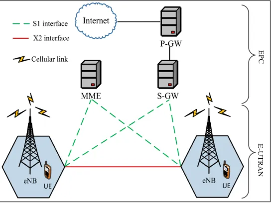
The network has a flat all-IP architecture specifically designed to achieve lower latencies (less than 5 ms in the RAN), thus achieving well reduced Capital Expenditure (CAPEX) and Operational Expenditure (OPEX) [9]. A comprehensive illustration of the LTE network architecture is shown in Figure 2-3. The Evolved packet core (EPC) consists of the protocol data network gateway (P-GW), serving gate-way (S-GW), and the mobility management entity (MME). The P-GW connects the EPC to the external IP networks, the S-GW conveys IP data traffic between UE and external network, and the MME coordinates the signalling for the Evolved UMTS terrestrial RAN (E-UTRAN) access [9].
S-GW MME P-GW Internet Cellular link X2 interface S1 interface E P C E -U T R A N eNB UE eNB UE
Figure 2-3 A comprehensive LTE network architecture
The LTE network provides peak rate of about 100 Mbps and 50 Mbps DL and UL respectively with the initial release (release 8), using a scalable transmission
OFDMA, while the UL with SC-FDMA, which in turn improves the SE and improves battery life of the UE respectively [9]. The SC-FDMA uses single carrier modulation with frequency domain equalisation, hence requires similar complexity to the OFDMA systems [21]. However, SC-FDMA has a significant advantage compared to conventional OFDMA in terms of lower peak to average power ratio (PAPR) due to the single-carrier transmission, which therefore reduces UE power requirement for UL transmission as earlier stated. The physical signal is generated in layer 1 of the LTE frame structure, and is used to perform functions such as cell identification, radio channel estimation, and UE/system synchronisation with the network in the DL [51]. Both DL and UL use the pilot signals to tackle the error issues in data reception, thus ensuring reliable and efficient demodulation at the receiver (especially for higher order modulation). Out of the two frame structure types of the LTE (TDD and FDD), the FDD is optimised to coexist with the 3.84Mb/s UMTS system, hence commonly considered in most literature. It contains 10 sub-frames with a total of 10ms (each sub-frame having two slots of 0.5ms), and has similar frame structure for DL and UL (with different channels and signal positions respectively) [51]. Figure 2-4 presents a diagram of the LTE frame structures (both TDD and FDD).
(special subframe) (special subframe) fUL fDL/UL fDL Subframe DL UL #0 #1 #2 #3 #4 #5 #6 #7 #8 #9 FDD TDD
One radio frame, Tframe = 10 ms
DWPTS GP UPPTS
The network has a simple protocol structure at the Radio link control (RLC), Medium access control (MAC) and physical layers. Some of the functions performed by RLC and MAC layers include retransmission and data multiplexing, whereas the physical layer offer information transfer to the higher layers, and transmits turbo-coded data via QPSK, 16-QAM, or 64-QAM, then followed by OFDM modulation [9]. The subcarrier spacing of the LTE is 15 KHz (with two CP lengths), in both the UL and DL. One of the most outstanding characteristics of the LTE is its ability to utilise both the TDD and FDD frame structures. Hence LTE achieves an efficient QoS using both HARQ and selective repeat ARQ for occasional retransmissions, and also has an efficient use of its radio resources by using channel dependent scheduling in the time/frequency domain to exploit rapid channel quality variations.
The bandwidth allocated to a UE (i.e. DL) in an LTE network is in the form of a resource block (RB), which is a constituent of a resource grid (shown in Figure 2-5). The resource grid comprises of 12 subcarriers and a number of OFDM symbols which differs for different CP length and system bandwidth.
Tslo
t
NBW subcarriers
12 subcarriers
Resource
Element 7 symbols X 12 subcarriers (short CP), or, 6 symbols X 12 subcarriers (long CP) Downlink
The smallest time-frequency unit used for DL transmission is referred to as a resource element (one symbol on one subcarrier). The RB is a group of 12 subcarriers joining in frequency and one slot in time. A UE can be allocated more than a single RB based on its data rate requirement [51]. The total number of available RBs depends on the overall transmission bandwidth of the system, ranging from 1.25 to 20 MHz as shown in Table 2-1. Taking a 20 MHz bandwidth as an example from the table, a total of 100 RBs is available for data transmission for the whole UEs in the cell.
Table 2-1 Number of available RBs for different LTE bandwidths (DL) [51]
Bandwidth (MHz) 1.25 2.5 5.0 10.0 15.0 20.0 Subcarrier bandwidth (kHz) 15 Resource block bandwidth (kHz) 180 Number of available RBs 6 12 25 50 75 100
2.4
Enhancements in the LTE-Advanced networks
Shortly after finalising the initial releases of the LTE network, LTE-A (release 10) specifications were then approved by ITU as a true 4G network, having met the IMT-A requirements as mentioned in preceding section from [39]. The LTE-IMT-A network even shows slightly better capabilities in some aspects of the network performance compared to the IMT-A requirements as shown in Table 2-2. These include peak and cell edge SE for both DL and UL as shown in the table. This is however associated with the higher channel bandwidth (up to 100 MHz) specified for the LTE-A standard compared to the 40 MHz requirement of IMT-A. The proposal included major improvements on top of the initial release with full backward compatibility. These
primarily include enhanced antenna techniques (up to 8 X 8 and 4 X 4 MIMO for DL and UL respectively), and higher order modulation (up to 64 QAM modulation schemes). These influenced the significant improvement in data rates of the LTE-A network, with peak rate of up to 1 Gbps DL and around 500 Mbps UL compared to the initial release i.e. release 8 [52]. Additionally, a summary of SE targets defined for different antenna configurations are shown in Table 2-3. It should be noted that the SE targets in the table are specifically for a 10 MHz bandwidth channel in a multi-cell macro cellular environment [52].
Table 2-2 IMT-A requirement and LTE-A projected capability [53]
With the high achievable data rates specified for LTE networks, a major limiting
Item IMT-A requirement LTE-A capability
Peak data rate DL (Gbps) 1 1
Peak data rate UL (Gbps) 1 0.5
Spectrum allocation (MHz) Up to 40 Up to 100
Latency user plane (ms) 10 50
Latency control plane (ms) 100 50
Peak SE DL (bps/Hz) 15 30 Peak SE UL (bps/Hz) 6.75 15 Average SE DL (bps/Hz) 2.2 2.6 Average SE UL (bps/Hz) 1.4 2.0 Cell edge SE DL (bps/Hz) 0.06 0.09 Cell edge SE UL (bps/Hz) 0.03 0.07
edge of the universal reuse network (i.e. reuse factor of 1): inter-cell interference (from different cells/sectors) significantly affect the cell edge UEs SE. This in addition to signal attenuation (due to the distance of the UEs from the eNB and fading), especially in macro cells essentially affects the overall SE of the networks. Thus, the CoMP technology (which involves coordination between different cells) was specified for LTE-A so as to proffer solution to the inter-cell interference issue and increase the cell edge data rates/SE of UEs in the network.
Table 2-3 SE comparison for LTE release 8 with LTE-A targets [52]
Link Antenna configuration LTE Release 8 [bps/Hz] LTE-A [bps/Hz] Uplink 1x2 0.8 1.2 2x4 N.A 2.0 Downlink 2x2 1.6 2.4 4x2 1.7 2.6 4x4 2.7 3.7
2.4.1
Coordinated multipoint
CoMP transmission/reception is considered a key element in achieving the specified requirement of the LTE-A network. The technology spiked up a lot of research in both DL and UL implementations so as to improve the achievable data rates/SE of the network [54, 55]. Recently, field implementations have demonstrated the capacity enhancement of the coordination scheme as shown in [28]. While the UL CoMP is mainly vendor specific, the specification of DL CoMP schemes have been detailed by 3GPP [52]. These schemes are namely: Joint processing (JP) and coordinated
in facilitating the CoMP technology in LTE networks. It is specified as a virtual interface initiated in the event of hand-over and CoMP process, thus enabling a temporary communication between the eNB of communicating cells [58]. A model classifying the elements of the CoMP schemes is shown in Figure 2-6.
Interference Avoidance (IA) Interference Cancellation (IC) Joint transmission (JT) Dynamic cell selection (DCS) Coordinated Scheduling/beam forming Joint Processing
CoMP
Figure 2-6 Classification of the CoMP schemes [54]
For the JP scheme, RBs intended for a single UE is transmitted from different coordinating cells (i.e. the non-serving and serving cells), referred to as Joint transmission (JT). Another technique for the JP scheme is referred to as Dynamic cell selection (DCS), where the RB allocated to a UE is transmitted from a single cell (among the coordinating cells), which is selected based on the channel condition by the central BS controller. In the CoBF/CoSH schemes, the RBs to a cell edge UE are always transmitted from a single cell. This is done by the cooperating cells coordinating their scheduling (i.e. when to allocate the UEs RB), or applying beamforming (signal processing to direct signal transmission) techniques [59] to mitigate interference on the cell edge UEs. While the CoMP scheme is broadly classified into CoBF and JP techniques, various algorithms have been proposed in
based on UE location is proposed in this research, where system-level simulation results showing performance improvement of implementing the algorithm is presented and discussed in Chapter 4 of this thesis.
2.5
Efficient spectrum utilisation with maximum use of
cellular resources in future networks
One significant limitation in wireless network implementation in general is the scarcity of the finite spectrum, especially radio frequency ranging from 3 kHz to 300 GHz as shown in Figure 2-7. The congested frequency is being utilised for WiFi, 3G, and Bluetooth standards (amongst others) as illustrated in the figure. The increasing requirement of wireless broadband services has equally intensified the congestion of the spectrum. This has compelled strict regulations in individual regions around the world on how to effectively allocate and manage the limited spectrum to ensure efficient wireless communication.
Electric waves Infra-red Visible light Ultra violet X-rays Gamma rays Cosmic Rays Radio waves VLF LF MF HF VHF UHF SHF EHF kHz MHz HHz Long wave radio Medium
wave radio radioFM TV
GSMWiFiBluetooth Microwave radio links 3G 3 30 300 3 30 300 3 30 300 Increasing range Decreasing bandwidth Decreasing range Increasing bandwidth
Figure 2-7 Illustration of the radio frequency spectrum
spectrums within the congestion zone as (shaded spectrum region in Figure 2-7). While the cellular spectrum is saturated with active users, the TV band has been identified to have significant redundancy in spectrum usage (as it is allocated a static spectrum that is seldom used). An example is a study conducted in some populated countries (Malaysia and China), which shows that only about 11% of the TV spectrum was actively utilised at the time of acquiring the statistics in the regions [35, 36]. The outcomes of such studies have sparked increasing research in finding solutions to making efficient use of the spectrum. This could be a significant factor for timely and cost-effective implementation of future wireless networks, since acquiring new spectrum is not only expensive but has been shown to hinder the timely migration to new technologies as discussed earlier. Thus to resolve the spectrum congestion and white spaces (unused spectrum) for the cellular and TV bands, inherent technologies such as D2D communication and CR are highly considered in current research initiatives to facilitate maximum usage of the spectrum. Thus D2D communication underlaying the cellular networks is projected to ensure effective reuse of the cellular resources (i.e. RBs), while CR is employed to eliminate spectrum holes by sensing/identify unused spectrum and temporarily allocating it to active unlicensed users when required. Additionally, the existing concept of Multihop (MH) transmission scheme is emphasised to enable cellular coverage extension and also to establish a common link between small cells and micro cells in the trending Heterogeneous Network (HetNet) implementation. The aforementioned technologies are discussed with further details in the following subsections;
2.5.1
Cognitive radio
spectrum) for transmission, commonly referred to as opportunistic transmission. It is one of the technologies envisioned to proffer solution to the spectrum underutilisation discussed earlier in this section. The technology immensely suits the strict policies of fixed long-term spectrum allocation for the wireless communications. Wireless standards such as ZigBee and WiFi have been a success in the WLANs over the years, utilising the unlicensed spectrum (mainly in the 2.4 GHz spectrum band), which is also currently becoming crowded [34]. Some key aspects of the technology include spectrum sensing (i.e. identifying white spaces) [61], and interference management between the primary (licensed) users and secondary (unlicensed) users [62]. Although this technology is out of the scope of this thesis, it is however generally summarised in this subsection as it h
![Figure 1-1 illustrates an estimate of active mobile subscribers worldwide from 2011 to 2014 [3]](https://thumb-us.123doks.com/thumbv2/123dok_us/508316.2559988/20.892.135.654.772.1106/figure-illustrates-estimate-active-mobile-subscribers-worldwide-from.webp)
![Figure 1-4 Range expansion with heterogeneous cellular implementation [31]](https://thumb-us.123doks.com/thumbv2/123dok_us/508316.2559988/27.892.141.758.761.1101/figure-range-expansion-heterogeneous-cellular-implementation.webp)
![Figure 2-10 Consolidation of technologies for future 5G cellular architecture [89]](https://thumb-us.123doks.com/thumbv2/123dok_us/508316.2559988/59.892.136.712.390.815/figure-consolidation-technologies-future-g-cellular-architecture.webp)
![Figure 3-2 Link-system level modelling of the LTE network SLS [103]](https://thumb-us.123doks.com/thumbv2/123dok_us/508316.2559988/68.892.136.648.567.946/figure-link-system-level-modelling-lte-network-sls.webp)