Technical Report
NREL/TP-500-38060
February 2009
Definition of a 5-MW Reference
Wind Turbine for Offshore
System Development
J. Jonkman, S. Butterfield, W. Musial, and
G. Scott
National Renewable Energy Laboratory
Technical Report
NREL/TP-500-38060
February 2009
Definition of a 5-MW Reference
Wind Turbine for Offshore
System Development
J. Jonkman, S. Butterfield, W. Musial, and
G. Scott
NOTICE
This report was prepared as an account of work sponsored by an agency of the United States government.
Neither the United States government nor any agency thereof, nor any of their employees, makes any
warranty, express or implied, or assumes any legal liability or responsibility for the accuracy, completeness, or
usefulness of any information, apparatus, product, or process disclosed, or represents that its use would not
infringe privately owned rights. Reference herein to any specific commercial product, process, or service by
trade name, trademark, manufacturer, or otherwise does not necessarily constitute or imply its endorsement,
recommendation, or favoring by the United States government or any agency thereof. The views and
opinions of authors expressed herein do not necessarily state or reflect those of the United States
government or any agency thereof.
Available electronically at
Available for a processing fee to U.S. Department of Energy
and its contractors, in paper, from:
U.S. Department of Energy
Office of Scientific and Technical Information
P.O. Box 62
Oak Ridge, TN 37831-0062
phone: 865.576.8401
fax: 865.576.5728
email:
Available for sale to the public, in paper, from:
U.S. Department of Commerce
National Technical Information Service
5285 Port Royal Road
Springfield, VA 22161
phone: 800.553.6847
fax: 703.605.6900
email:
online ordering:
Acronyms and Abbreviations
ADAMS
®
= Automatic Dynamic Analysis of Mechanical Systems
A2AD
= ADAMS-to-AeroDyn
BEM
= blade-element / momentum
CM
= center of mass
DLL
= dynamic link library
DOE
= U.S. Department of Energy
DOF
= degree of freedom
DOWEC = Dutch Offshore Wind Energy Converter project
DU
= Delft University
ECN
= Energy Research Center of the Netherlands
equiripple = equalized-ripple
FAST
= Fatigue, Aerodynamics, Structures, and Turbulence
GE
= General Electric
IEA
= International Energy Agency
MSL
= mean sea level
NACA
= National Advisory Committee for Aeronautics
NREL
= National Renewable Energy Laboratory
NWTC
= National Wind Technology Center
OCS
= offshore continental shelf
OC3
= Offshore Code Comparison Collaborative
PI
= proportional-integral
PID
= proportional-integral-derivative
RECOFF = Recommendations for Design of Offshore Wind Turbines project
WindPACT = Wind Partnerships for Advanced Component Technology project
w.r.t.
= with respect to
Nomenclature
A
d
= discrete-time state matrix
B
d
= discrete-time input matrix
C
d
= discrete-time output state matrix
C
φ
= effective damping in the equation of motion for the rotor-speed error
D
d
= discrete-time input transmission matrix
f
c
= corner frequency
GK
= gain-correction factor
I
Drivetrain
= drivetrain inertia cast to the low-speed shaft
I
Gen
= generator inertia relative to the high-speed shaft
I
Rotor
= rotor inertia
K
D
= blade-pitch controller derivative gain
K
I
= blade-pitch controller integral gain
K
P
= blade-pitch controller proportional gain
K
φ
= effective stiffness in the equation of motion for the rotor-speed error
M
φ
= effective inertia (mass) in the equation of motion for the rotor-speed error
n
= discrete-time-step counter
N
Gear
= high-speed to low-speed gearbox ratio
P
= mechanical power
P
0
= rated mechanical power
P
θ
∂ ∂
= sensitivity of the aerodynamic power to the rotor-collective blade-pitch angle
t
= simulation time
T
Aero
= aerodynamic torque in the low-speed shaft
T
s
= discrete-time step
u
= unfiltered generator speed
x
= for the control-measurement filter, the filter state
x
,
y
,
z
= set of orthogonal axes making up a reference-frame coordinate system
y
= for the control-measurement filter, the filtered generator speed
α
= low-pass filter coefficient
Δθ
= small perturbation of the blade-pitch angles about their operating point
ΔΩ
= small perturbation of the low-speed shaft rotational speed about the rated speed
∆Ω
= low-speed shaft rotational acceleration
ζ
φ
= damping ratio of the response associated with the equation of motion for the
rotor-speed error
θ
= full-span rotor-collective blade-pitch angle
θ
K
= rotor-collective blade-pitch angle at which the pitch sensitivity has doubled from
its value at the rated operating point
π
= the ratio of a circle’s circumference to its diameter
φ
= the integral of
ϕ
with respect to time
ϕ
= small perturbation of the low-speed shaft rotational speed about the rated speed
ϕ
= low-speed shaft rotational acceleration
Ω
= low-speed shaft rotational speed
Ω
0
= rated low-speed shaft rotational speed
ω
φn
=
natural frequency of the response associated with the equation of motion for the
Executive Summary
To support concept studies aimed at assessing offshore wind technology, we developed the
specifications of a representative utility-scale multimegawatt turbine now known as the “NREL
offshore 5-MW baseline wind turbine.” This wind turbine is a conventional three-bladed upwind
variable-speed variable blade-pitch-to-feather-controlled turbine. To create the model, we
obtained some broad design information from the published documents of turbine manufacturers,
with a heavy emphasis on the REpower 5M machine. Because detailed data was unavailable,
however, we also used the publicly available properties from the conceptual models in the
WindPACT, RECOFF, and DOWEC projects. We then created a composite from these data,
extracting the best available and most representative specifications. This report documents the
specifications of the NREL offshore 5-MW baseline wind turbine—including the aerodynamic,
structural, and control-system properties—and the rationale behind its development. The model
has been, and will likely continue to be, used as a reference by research teams throughout the
world to standardize baseline offshore wind turbine specifications and to quantify the benefits of
advanced land- and sea-based wind energy technologies.
Table of Contents
1 Introduction ... 1
2 Blade Structural Properties ... 5
3 Blade Aerodynamic Properties ... 7
4 Hub and Nacelle Properties ... 12
5 Drivetrain Properties ... 14
6 Tower Properties ... 15
7 Baseline Control System Properties ... 17
7.1 Baseline Control-Measurement Filter ...17
7.2 Baseline Generator-Torque Controller ...19
7.3 Baseline Blade-Pitch Controller ...20
7.4 Baseline Blade-Pitch Actuator ...26
7.5 Summary of Baseline Control System Properties ...26
8 FAST with AeroDyn and ADAMS with AeroDyn Models... 28
9 Full-System Natural Frequencies and Steady-State Behavior ... 30
10 Conclusions ... 33
References ... 34
Appendix A FAST Input Files ... 38
A.1 Primary Input File ...38
A.2 Blade Input File – NRELOffshrBsline5MW_Blade.dat ...40
A.3 Tower Input File – NRELOffshrBsline5MW_Tower_Onshore.dat ...41
A.4 ADAMS Input File – NRELOffshrBsline5MW_ADAMSSpecific.dat ...42
A.5 Linearization Input File – NRELOffshrBsline5MW_Linear.dat ...43
Appendix B AeroDyn Input Files ... 44
B.1 Primary Input File – NRELOffshrBsline5MW_AeroDyn.ipt ...44
B.5 Airfoil-Data Input File – DU35_A17.dat ...47
B.6 Airfoil-Data Input File – DU30_A17.dat ...48
B.7 Airfoil-Data Input File – DU25_A17.dat ...50
B.8 Airfoil-Data Input File – DU21_A17.dat ...52
B.9 Airfoil-Data Input File – NACA64_A17.dat ...54
List of Tables
Table 1-1. Gross Properties Chosen for the NREL 5-MW Baseline Wind Turbine
... 2
Table 2-1. Distributed Blade Structural Properties
... 5
Table 2-2. Undistributed Blade Structural Properties
... 6
Table 3-1. Distributed Blade Aerodynamic Properties
... 7
Table 4-1. Nacelle and Hub Properties
... 13
Table 5-1. Drivetrain Properties
... 14
Table 6-1. Distributed Tower Properties
... 15
Table 6-2. Undistributed Tower Properties
... 16
Table 7-1. Sensitivity of Aerodynamic Power to Blade Pitch in Region 3
... 23
Table 7-2. Baseline Control System Properties
... 27
List of Figures
Figure 3-1. Corrected coefficients of the DU40 airfoil
... 9
Figure 3-2. Corrected coefficients of the DU35 airfoil
... 9
Figure 3-3. Corrected coefficients of the DU30 airfoil
... 10
Figure 3-4. Corrected coefficients of the DU25 airfoil
... 10
Figure 3-5. Corrected coefficients of the DU21 airfoil
... 11
Figure 3-6. Corrected coefficients of the NACA64 airfoil
... 11
Figure 7-1. Bode plot of generator speed low-pass filter frequency response
... 18
Figure 7-2. Torque-versus-speed response of the variable-speed controller
... 20
Figure 7-3. Best-fit line of pitch sensitivity in Region 3
... 24
Figure 7-4. Baseline blade-pitch control system gain-scheduling law
... 25
Figure 7-5. Flowchart of the baseline control system
... 27
1 Introduction
The U.S. Department of Energy’s (DOE’s) National Renewable Energy Laboratory (NREL),
through the National Wind Technology Center (NWTC), has sponsored conceptual studies aimed
at assessing offshore wind technology suitable in the shallow and deep waters off the U.S.
offshore continental shelf (OCS) and other offshore sites worldwide. To obtain useful
information from such studies, use of realistic and standardized input data is required. This
report documents the turbine specifications of what is now called the “NREL offshore 5-MW
baseline wind turbine” and the rationale behind its development. Our objective was to establish
the detailed specifications of a large wind turbine that is representative of typical utility-scale
land- and sea-based multimegawatt turbines, and suitable for deployment in deep waters.
Before establishing the detailed specifications, however, we had to choose the basic size and
power rating of the machine. Because of the large portion of system costs in the support
structure of an offshore wind system, we understood from the outset that if a deepwater wind
system is to be cost-effective, each individual wind turbine must be rated at 5 MW or higher
[23].
1
•
Feasible floater configurations for offshore wind turbines scoped out by Musial,
Butterfield, and Boone [
Ratings considered for the baseline ranged from 5 MW to 20 MW. We decided that the
baseline should be 5 MW because it has precedence:
23] were based on the assumption of a 5-MW unit.
•
Unpublished DOE offshore cost studies were based on a rotor diameter of 128 m, which
is a size representative of a 5- to 6-MW wind turbine.
•
The land-based Wind Partnerships for Advanced Component Technology (WindPACT)
series of studies, considered wind turbine systems rated up to 5 MW [19,24,29].
•
The Recommendations for Design of Offshore Wind Turbines project (known as
RECOFF) based its conceptual design calculations on a wind turbine with a 5-MW rating
[32].
•
The Dutch Offshore Wind Energy Converter (DOWEC) project based its conceptual
design calculations on a wind turbine with a 6-MW rating [8,14,17].
•
At the time of this writing, the largest wind turbine prototypes in the world—the
Multibrid M5000 [5,21,22] and the REpower 5M [18,26,27]—each had a 5-MW rating.
We gathered the publicly available information on the Multibrid M5000 and REpower 5M
prototype wind turbines. And because detailed information on these machines was unavailable,
we also used the publicly available properties from the conceptual models used in the
WindPACT, RECOFF, and DOWEC projects. These models contained much greater detail than
was available about the prototypes. We then created a composite from these models, extracting
the best available and most representative specifications.
The Multibrid M5000 machine has a significantly higher tip speed than typical onshore wind
turbines and a lower tower-top mass than would be expected from scaling laws previously
developed in one of the WindPACT studies [29]. In contrast, the REpower 5M machine has
properties that are more “expected” and “conventional.” For this reason, we decided to use the
specifications of the REpower 5M machine as the target specifications
2
The wind turbine used in the DOWEC project had a slightly higher rating than the rating of the
REpower 5M machine, but many of the other basic properties of the DOWEC turbine matched
the REpower 5M machine very well. In fact, the DOWEC turbine matched many of the
properties of the REpower 5M machine better than the turbine properties derived for the
WindPACT and RECOFF studies.
for our baseline model.
3
The REpower 5M machine has a rotor radius of about 63 m. Wanting the same radius and the
lowest reasonable hub height possible to minimize the overturning moment acting on an offshore
substructure, we decided that the hub height for the baseline wind turbine should be 90 m. This
would give a 15-m air gap between the blade tips at their lowest point when the wind turbine is
undeflected and an estimated extreme 50-year individual wave height of 30 m (i.e., 15-m
amplitude). The additional gross properties we chose for the NREL 5-MW baseline wind
turbine, most of which are identical to those of the REpower 5M, are given in
As a result of these similarities, we made the heaviest use of
data from the DOWEC study in our development of the NREL offshore 5-MW baseline wind
turbine.
Table 1-1. The
(
x
,
y
,
z
) coordinates of the overall center of mass (CM) location of the wind turbine are indicated
in a tower-base coordinate system, which originates along the tower centerline at ground or mean
2
Note that we established the target specifications using information about the REpower 5M machine that was
published in January 2005 [26,27]. Some of the information presented in Refs. [26] and [27] disagrees with more
recently published information. For example, the published nacelle and rotor masses of the REpower 5M are higher
in the more recent publications.
3
This was probably because the REpower 5M prototype utilized blades provided by LM Glasfiber [18], a company
that helped establish the structural properties of the blades used in the DOWEC study.
Table 1-1. Gross Properties Chosen for the NREL 5-MW Baseline
Wind Turbine
Rating
5 MW
Rotor Orientation, Configuration
Upwind, 3 Blades
Control
Variable Speed, Collective Pitch
Drivetrain
High Speed, Multiple-Stage Gearbox
Rotor, Hub Diameter
126 m, 3 m
Hub Height
90 m
Cut-In, Rated, Cut-Out Wind Speed
3 m/s, 11.4 m/s, 25 m/s
Cut-In, Rated Rotor Speed
6.9 rpm, 12.1 rpm
Rated Tip Speed
80 m/s
Overhang, Shaft Tilt, Precone
5 m, 5º, 2.5º
Rotor Mass
110,000 kg
Nacelle Mass
240,000 kg
Tower Mass
347,460 kg
sea level (MSL). The
x
-axis of this coordinate system is directed nominally downwind, the
y
-axis is directed transverse to the nominal wind direction, and the
z
-axis is directed vertically from
the tower base to the yaw bearing.
The actual REpower 5M wind turbine uses blades with built-in prebend as a means of increasing
tower clearance without a large rotor overhang. Because many of the available simulation tools
and design codes cannot support blades with built-in prebend, we chose a 2.5°-upwind precone
in the baseline wind turbine to represent the smaller amount of precone and larger amount of
prebend that are built into the actual REpower 5M machine.
The rotor diameter indicated in Table 1-1 ignores the effect of blade precone, which reduces the
actual diameter and swept area. The exact rotor diameter in the turbine specifications (assuming
that the blades are undeflected) is actually (126 m) ×
cos
(2.5°) = 125.88 m and the actual swept
area is (
π
/4) × (125.88 m)
2
= 12,445.3 m
2
.
We present other information about this model as follows:
•
The blade structural properties in Section 2
•
The blade aerodynamic properties in Section 3
•
The hub and nacelle properties in Section 4
•
The drivetrain properties in Section 5
•
The tower properties in Section 6
•
The baseline control system properties in Section 7
•
The aero-servo-elastic FAST (Fatigue, Aerodynamics, Structures, and Turbulence) [11]
with AeroDyn [16,20] and MSC.ADAMS
®
(Automatic Dynamic Analysis of Mechanical
Systems) with A2AD (ADAMS-to-AeroDyn)
4
[ ,15] and AeroDyn models of the wind
6
turbine in Section 8
•
The basic responses of the land-based version of the wind turbine, including its
full-system natural frequencies and steady-state behavior in Section 9.
Although we summarize much of this information
5
for conciseness and clarity, Section
7
contains a high level of detail about the development of the wind turbine’s baseline control
system. These details are provided because they are fundamental to the development of more
advanced control systems.
The NREL offshore 5-MW baseline wind turbine has been used to establish the reference
specifications for a number of research projects supported by the U.S. DOE’s Wind &
Hydropower Technologies Program [1,2,7,12,28,33,34]. In addition, the integrated European
Union UpWind research program
6
and the International Energy Agency (IEA) Wind Annex
XXIII Subtask 2
7
Offshore Code Comparison Collaboration (OC3) [ ,25] have adopted the
13
NREL offshore 5-MW baseline wind turbine as their reference model. The model has been, and
will likely continue to be, used as a reference by research teams throughout the world to
standardize baseline offshore wind turbine specifications and to quantify the benefits of
advanced land- and sea-based wind energy technologies.
6
Web site: http://www.upwind.eu/default.aspx
2 Blade Structural Properties
The NREL offshore 5-MW baseline wind turbine has three blades. We based the distributed
blade structural properties of each blade on the structural properties of the 62.6-m-long LM
Glasfiber blade used in the DOWEC study (using the data given in Appendix A of Ref. [17]).
Because the blades in the DOWEC study were 1.1 m longer than the 61.5-m-long LM Glasfiber
blades [18] used on the actual REpower 5M machine, we truncated the 62.6-m blades at 61.5-m
span to obtain the structural properties of the NREL 5-MW baseline blades (we found the
structural properties at the blade tip by interpolating between the 61.2-m and 61.7-m stations
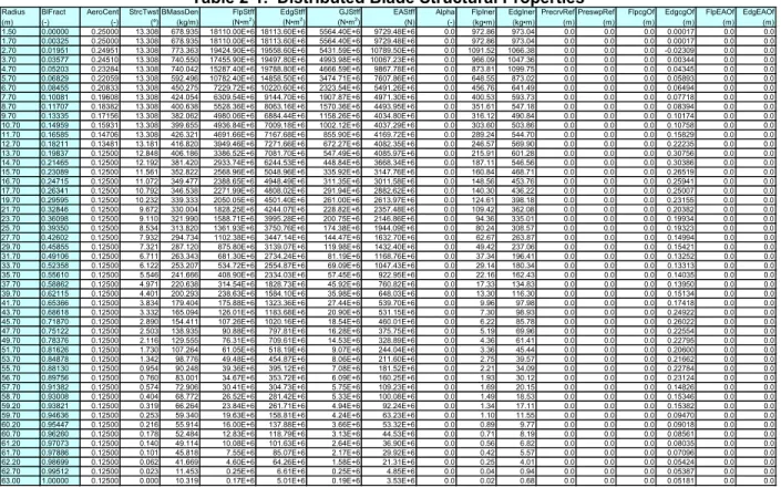
given in Appendix A of Ref. [17]). Table 2-1 lists the resulting properties.
The entries in the first column of Table 2-1, labeled “Radius,” are the spanwise locations along
the blade-pitch axis relative to the rotor center (apex). “BlFract” is the fractional distance along
the blade-pitch axis from the root (0.0) to the tip (1.0). We located the blade root 1.5 m along the
pitch axis from the rotor center, equivalent to half the hub diameter listed in Table 1-1.
“AeroCent” is the name of a FAST input parameter. The FAST code assumes that the
blade-pitch axis passes through each airfoil section at 25% chord. By definition, then, the quantity
(AeroCent
−
0.25) is the fractional distance to the aerodynamic center from the blade-pitch axis
along the chordline, positive toward the trailing edge. Thus, at the root (i.e., BlFract = 0.0),
AeroCent = 0.25 means that the aerodynamic center lies on the blade-pitch axis [because (0.25
−
0.25) = 0.0], and at the tip (i.e., BlFract = 1.0), AeroCent = 0.125 means that the aerodynamic
center lies 0.125 chordlengths toward the leading edge from the blade-pitch axis [because (0.125
Table 2-1. Distributed Blade Structural Properties
Radius BlFract AeroCent StrcTwst BMassDen FlpStff EdgStff GJStff EAStff Alpha FlpIner EdgIner PrecrvRef PreswpRef FlpcgOf EdgcgOf FlpEAOf EdgEAOf (m) (-) (-) (º) (kg/m) (N•m2) (N•m2) (N•m2) (N) (-) (kg•m) (kg•m) (m) (m) (m) (m) (m) (m)
1.50 0.00000 0.25000 13.308 678.935 18110.00E+6 18113.60E+6 5564.40E+6 9729.48E+6 0.0 972.86 973.04 0.0 0.0 0.0 0.00017 0.0 0.0 1.70 0.00325 0.25000 13.308 678.935 18110.00E+6 18113.60E+6 5564.40E+6 9729.48E+6 0.0 972.86 973.04 0.0 0.0 0.0 0.00017 0.0 0.0 2.70 0.01951 0.24951 13.308 773.363 19424.90E+6 19558.60E+6 5431.59E+6 10789.50E+6 0.0 1091.52 1066.38 0.0 0.0 0.0 -0.02309 0.0 0.0 3.70 0.03577 0.24510 13.308 740.550 17455.90E+6 19497.80E+6 4993.98E+6 10067.23E+6 0.0 966.09 1047.36 0.0 0.0 0.0 0.00344 0.0 0.0 4.70 0.05203 0.23284 13.308 740.042 15287.40E+6 19788.80E+6 4666.59E+6 9867.78E+6 0.0 873.81 1099.75 0.0 0.0 0.0 0.04345 0.0 0.0 5.70 0.06829 0.22059 13.308 592.496 10782.40E+6 14858.50E+6 3474.71E+6 7607.86E+6 0.0 648.55 873.02 0.0 0.0 0.0 0.05893 0.0 0.0 6.70 0.08455 0.20833 13.308 450.275 7229.72E+6 10220.60E+6 2323.54E+6 5491.26E+6 0.0 456.76 641.49 0.0 0.0 0.0 0.06494 0.0 0.0 7.70 0.10081 0.19608 13.308 424.054 6309.54E+6 9144.70E+6 1907.87E+6 4971.30E+6 0.0 400.53 593.73 0.0 0.0 0.0 0.07718 0.0 0.0 8.70 0.11707 0.18382 13.308 400.638 5528.36E+6 8063.16E+6 1570.36E+6 4493.95E+6 0.0 351.61 547.18 0.0 0.0 0.0 0.08394 0.0 0.0 9.70 0.13335 0.17156 13.308 382.062 4980.06E+6 6884.44E+6 1158.26E+6 4034.80E+6 0.0 316.12 490.84 0.0 0.0 0.0 0.10174 0.0 0.0 10.70 0.14959 0.15931 13.308 399.655 4936.84E+6 7009.18E+6 1002.12E+6 4037.29E+6 0.0 303.60 503.86 0.0 0.0 0.0 0.10758 0.0 0.0 11.70 0.16585 0.14706 13.308 426.321 4691.66E+6 7167.68E+6 855.90E+6 4169.72E+6 0.0 289.24 544.70 0.0 0.0 0.0 0.15829 0.0 0.0 12.70 0.18211 0.13481 13.181 416.820 3949.46E+6 7271.66E+6 672.27E+6 4082.35E+6 0.0 246.57 569.90 0.0 0.0 0.0 0.22235 0.0 0.0 13.70 0.19837 0.12500 12.848 406.186 3386.52E+6 7081.70E+6 547.49E+6 4085.97E+6 0.0 215.91 601.28 0.0 0.0 0.0 0.30756 0.0 0.0 14.70 0.21465 0.12500 12.192 381.420 2933.74E+6 6244.53E+6 448.84E+6 3668.34E+6 0.0 187.11 546.56 0.0 0.0 0.0 0.30386 0.0 0.0 15.70 0.23089 0.12500 11.561 352.822 2568.96E+6 5048.96E+6 335.92E+6 3147.76E+6 0.0 160.84 468.71 0.0 0.0 0.0 0.26519 0.0 0.0 16.70 0.24715 0.12500 11.072 349.477 2388.65E+6 4948.49E+6 311.35E+6 3011.58E+6 0.0 148.56 453.76 0.0 0.0 0.0 0.25941 0.0 0.0 17.70 0.26341 0.12500 10.792 346.538 2271.99E+6 4808.02E+6 291.94E+6 2882.62E+6 0.0 140.30 436.22 0.0 0.0 0.0 0.25007 0.0 0.0 19.70 0.29595 0.12500 10.232 339.333 2050.05E+6 4501.40E+6 261.00E+6 2613.97E+6 0.0 124.61 398.18 0.0 0.0 0.0 0.23155 0.0 0.0 21.70 0.32846 0.12500 9.672 330.004 1828.25E+6 4244.07E+6 228.82E+6 2357.48E+6 0.0 109.42 362.08 0.0 0.0 0.0 0.20382 0.0 0.0 23.70 0.36098 0.12500 9.110 321.990 1588.71E+6 3995.28E+6 200.75E+6 2146.86E+6 0.0 94.36 335.01 0.0 0.0 0.0 0.19934 0.0 0.0 25.70 0.39350 0.12500 8.534 313.820 1361.93E+6 3750.76E+6 174.38E+6 1944.09E+6 0.0 80.24 308.57 0.0 0.0 0.0 0.19323 0.0 0.0 27.70 0.42602 0.12500 7.932 294.734 1102.38E+6 3447.14E+6 144.47E+6 1632.70E+6 0.0 62.67 263.87 0.0 0.0 0.0 0.14994 0.0 0.0 29.70 0.45855 0.12500 7.321 287.120 875.80E+6 3139.07E+6 119.98E+6 1432.40E+6 0.0 49.42 237.06 0.0 0.0 0.0 0.15421 0.0 0.0 31.70 0.49106 0.12500 6.711 263.343 681.30E+6 2734.24E+6 81.19E+6 1168.76E+6 0.0 37.34 196.41 0.0 0.0 0.0 0.13252 0.0 0.0 33.70 0.52358 0.12500 6.122 253.207 534.72E+6 2554.87E+6 69.09E+6 1047.43E+6 0.0 29.14 180.34 0.0 0.0 0.0 0.13313 0.0 0.0 35.70 0.55610 0.12500 5.546 241.666 408.90E+6 2334.03E+6 57.45E+6 922.95E+6 0.0 22.16 162.43 0.0 0.0 0.0 0.14035 0.0 0.0 37.70 0.58862 0.12500 4.971 220.638 314.54E+6 1828.73E+6 45.92E+6 760.82E+6 0.0 17.33 134.83 0.0 0.0 0.0 0.13950 0.0 0.0 39.70 0.62115 0.12500 4.401 200.293 238.63E+6 1584.10E+6 35.98E+6 648.03E+6 0.0 13.30 116.30 0.0 0.0 0.0 0.15134 0.0 0.0 41.70 0.65366 0.12500 3.834 179.404 175.88E+6 1323.36E+6 27.44E+6 539.70E+6 0.0 9.96 97.98 0.0 0.0 0.0 0.17418 0.0 0.0 43.70 0.68618 0.12500 3.332 165.094 126.01E+6 1183.68E+6 20.90E+6 531.15E+6 0.0 7.30 98.93 0.0 0.0 0.0 0.24922 0.0 0.0 45.70 0.71870 0.12500 2.890 154.411 107.26E+6 1020.16E+6 18.54E+6 460.01E+6 0.0 6.22 85.78 0.0 0.0 0.0 0.26022 0.0 0.0 47.70 0.75122 0.12500 2.503 138.935 90.88E+6 797.81E+6 16.28E+6 375.75E+6 0.0 5.19 69.96 0.0 0.0 0.0 0.22554 0.0 0.0 49.70 0.78376 0.12500 2.116 129.555 76.31E+6 709.61E+6 14.53E+6 328.89E+6 0.0 4.36 61.41 0.0 0.0 0.0 0.22795 0.0 0.0 51.70 0.81626 0.12500 1.730 107.264 61.05E+6 518.19E+6 9.07E+6 244.04E+6 0.0 3.36 45.44 0.0 0.0 0.0 0.20600 0.0 0.0 53.70 0.84878 0.12500 1.342 98.776 49.48E+6 454.87E+6 8.06E+6 211.60E+6 0.0 2.75 39.57 0.0 0.0 0.0 0.21662 0.0 0.0 55.70 0.88130 0.12500 0.954 90.248 39.36E+6 395.12E+6 7.08E+6 181.52E+6 0.0 2.21 34.09 0.0 0.0 0.0 0.22784 0.0 0.0 56.70 0.89756 0.12500 0.760 83.001 34.67E+6 353.72E+6 6.09E+6 160.25E+6 0.0 1.93 30.12 0.0 0.0 0.0 0.23124 0.0 0.0 57.70 0.91382 0.12500 0.574 72.906 30.41E+6 304.73E+6 5.75E+6 109.23E+6 0.0 1.69 20.15 0.0 0.0 0.0 0.14826 0.0 0.0 58.70 0.93008 0.12500 0.404 68.772 26.52E+6 281.42E+6 5.33E+6 100.08E+6 0.0 1.49 18.53 0.0 0.0 0.0 0.15346 0.0 0.0
−
0.25) =
−
0.125].
The flapwise and edgewise section stiffness and inertia values, “FlpStff,” “EdgStff,” “FlpIner,”
and “EdgIner” in Table 2-1, are given about the principal structural axes of each cross section as
oriented by the structural-twist angle, “StrcTwst.” The values of the structural twist were
assumed to be identical to the aerodynamic twist discussed in Section 3.
“GJStff” represents the values of the blade torsion stiffness. Because the DOWEC blade data did
not contain extensional stiffness information, we estimated the blade extensional stiffness
values—“EAStff” in Table 2-1—to be 10
7
times the average mass moment of inertia at each
blade station. This came from a rule of thumb derived from the data available in the WindPACT
rotor design study [19], but the exact values are not important because of the low rotational
speed of the rotor.
The edgewise CM offset values, “EdgcgOf,” are the distances in meters along the chordline from
the blade-pitch axis to the CM of the blade section, positive toward the trailing edge. We
neglected the insignificant values of the flapwise CM offsets, “FlpcgOf,” and flapwise and
edgewise elastic offsets, “FlpEAOf” and “EdgEAOf,” given in Appendix A of Ref. [17].
Instead, we assumed that they were zero as shown in Table 2-1.
The distributed blade section mass per unit length values, “BMassDen,” given in Table 2-1 are
the values documented in Appendix A of Ref. [17]. We increased these by 4.536% in the model
to scale the overall (integrated) blade mass to 17,740 kg, which was the nominal mass of the
blades in the REpower 5M prototype. In our baseline specifications, the nominal second mass
moment of inertia, nominal first mass moment of inertia, and the nominal radial CM location of
each blade are 11,776,047 kg
•
m
2
, 363,231 kg
•
m, and 20.475 m with respect to (w.r.t.) the blade
root, respectively.
We specified a structural-damping ratio of 0.477465% critical in all modes of the isolated blade,
which corresponds to the 3% logarithmic decrement used in the DOWEC study from page 20 of
Ref. [14].
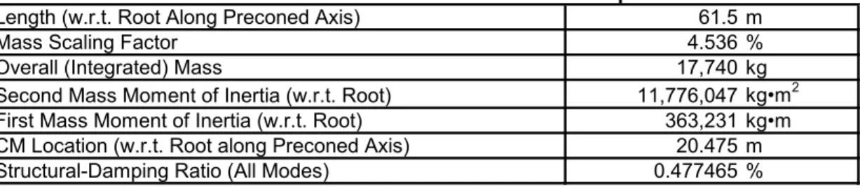
Table 2-2 summarizes the undistributed blade structural properties discussed in this section.
Table 2-2. Undistributed Blade Structural Properties
Length (w.r.t. Root Along Preconed Axis)
61.5 m
Mass Scaling Factor
4.536 %
Overall (Integrated) Mass
17,740 kg
Second Mass Moment of Inertia (w.r.t. Root)
11,776,047
kg•m
2First Mass Moment of Inertia (w.r.t. Root)
363,231
kg•m
CM Location (w.r.t. Root along Preconed Axis)
20.475 m
3 Blade Aerodynamic Properties
Similar to the blade structural properties, we based the blade aerodynamic properties of the
NREL 5-MW baseline wind turbine on the DOWEC blades (using the data described in Table 1
on page 13 of Ref. [14] and in Appendix A of Ref. [17]). We set the FAST with AeroDyn and
ADAMS with AeroDyn models to use 17 blade elements for integration of the aerodynamic and
structural forces. To better capture the large structural gradients at the blade root and the large
aerodynamic gradients at the blade tip, the 3 inboard and 3 outboard elements are two-thirds the
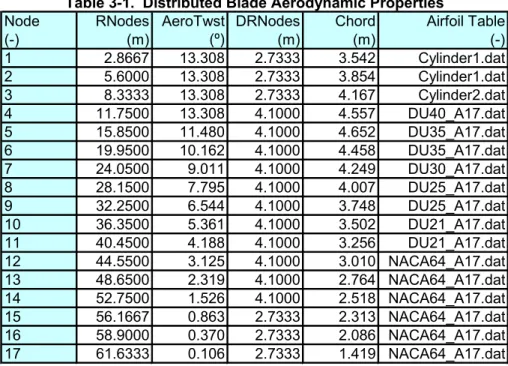
size of the 11 equally spaced midspan elements. Table 3-1 gives the aerodynamic properties at
the blade nodes, which are located at the center of the blade elements.
The blade node locations, labeled as “RNodes” in Table 3-1, are directed along the blade-pitch
axis from the rotor center (apex) to the blade cross sections. The element lengths, “DRNodes,”
sum to the total blade length of 61.5 m indicated in Table 2-2. The aerodynamic twist,
“AeroTwst,” as given in Table 3-1, are offset by
−
0.09182° from the values provided in
Appendix A of Ref. [17] to ensure that the zero-twist reference location is at the blade tip.
Integrating the chord distribution along the blade span reveals that the rotor solidity is roughly
5.16%.
As indicated in Table 3-1, we incorporated eight unique airfoil-data tables for the NREL offshore
5-MW baseline wind turbine. The two innermost airfoil tables represent cylinders with drag
coefficients of 0.50 (Cylinder1.dat) and 0.35 (Cylinder2.dat) and no lift. We created the
remaining six airfoil tables by making corrections for three-dimensional behavior to the
two-dimensional airfoil-data coefficients of the six airfoils used in the DOWEC study (as detailed in
Table 3-1. Distributed Blade Aerodynamic Properties
Node
RNodes AeroTwst DRNodes
Chord
Airfoil Table
(-)
(m)
(º)
(m)
(m)
(-)
1
2.8667
13.308
2.7333
3.542
Cylinder1.dat
2
5.6000
13.308
2.7333
3.854
Cylinder1.dat
3
8.3333
13.308
2.7333
4.167
Cylinder2.dat
4
11.7500
13.308
4.1000
4.557
DU40_A17.dat
5
15.8500
11.480
4.1000
4.652
DU35_A17.dat
6
19.9500
10.162
4.1000
4.458
DU35_A17.dat
7
24.0500
9.011
4.1000
4.249
DU30_A17.dat
8
28.1500
7.795
4.1000
4.007
DU25_A17.dat
9
32.2500
6.544
4.1000
3.748
DU25_A17.dat
10
36.3500
5.361
4.1000
3.502
DU21_A17.dat
11
40.4500
4.188
4.1000
3.256
DU21_A17.dat
12
44.5500
3.125
4.1000
3.010 NACA64_A17.dat
13
48.6500
2.319
4.1000
2.764 NACA64_A17.dat
14
52.7500
1.526
4.1000
2.518 NACA64_A17.dat
15
56.1667
0.863
2.7333
2.313 NACA64_A17.dat
16
58.9000
0.370
2.7333
2.086 NACA64_A17.dat
17
61.6333
0.106
2.7333
1.419 NACA64_A17.dat
Appendix A of Ref. [14]).
8
9
In these airfoil tables, “DU” refers to Delft University and “NACA”
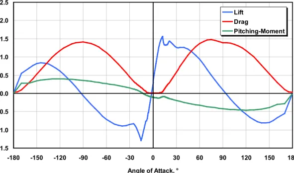
refers to the National Advisory Committee for Aeronautics. We used AirfoilPrep v2.0 [ ] to
“tailor” these airfoil data. We first corrected the lift and drag coefficients for rotational stall
delay using the Selig and Eggars method for 0° to 90° angles of attack. We then corrected the
drag coefficients using the Viterna method for 0° to 90° angles of attack assuming an aspect ratio
of 17. Finally, we estimated the Beddoes-Leishman dynamic-stall hysteresis parameters. We
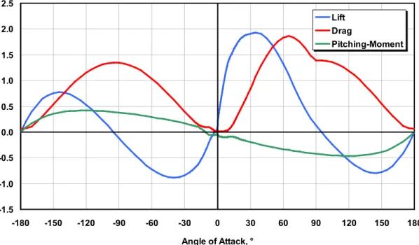
made no corrections to the DOWEC-supplied pitching-moment coefficients. The resulting
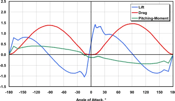
three-dimensionally corrected airfoil-data coefficients are illustrated graphically in Figure 3-1 through
Figure 3-6. The numerical values are documented in the AeroDyn airfoil-data input files that
make up Appendix B.
8
C. Lindenburg of the Energy Research Center of the Netherlands (ECN) provided numerical values for these
-1.5
-1.0
-0.5
0.0
0.5
1.0
1.5
2.0
2.5
-180
-150
-120
-90
-60
-30
0
30
60
90
120
150
180
Angle of Attack, °
Lift
Drag
Pitching-Moment
Figure 3-1. Corrected coefficients of the DU40 airfoil
-1.5
-1.0
-0.5
0.0
0.5
1.0
1.5
2.0
2.5
-180
-150
-120
-90
-60
-30
0
30
60
90
120
150
180
Angle of Attack, °
Lift
Drag
Pitching-Moment
-1.5
-1.0
-0.5
0.0
0.5
1.0
1.5
2.0
2.5
-180
-150
-120
-90
-60
-30
0
30
60
90
120
150
180
Angle of Attack, °
Lift
Drag
Pitching-Moment
Figure 3-3. Corrected coefficients of the DU30 airfoil
-1.5
-1.0
-0.5
0.0
0.5
1.0
1.5
2.0
2.5
-180
-150
-120
-90
-60
-30
0
30
60
90
120
150
180
Angle of Attack, °
Lift
Drag
Pitching-Moment
-1.5
-1.0
-0.5
0.0
0.5
1.0
1.5
2.0
2.5
-180
-150
-120
-90
-60
-30
0
30
60
90
120
150
180
Angle of Attack, °
Lift
Drag
Pitching-Moment
Figure 3-5. Corrected coefficients of the DU21 airfoil
-1.5
-1.0
-0.5
0.0
0.5
1.0
1.5
2.0
2.5
-180
-150
-120
-90
-60
-30
0
30
60
90
120
150
180
Angle of Attack, °
Lift
Drag
Pitching-Moment
4 Hub and Nacelle Properties
As indicated in Table 1-1, we located the hub of the NREL 5-MW baseline wind turbine 5 m
upwind of the tower centerline at an elevation of 90 m above the ground when the system is
undeflected. We also specified the same vertical distance from the tower top to the hub height
used by the DOWEC study—that is, 2.4 m (as specified in Table 6 on page 26 of Ref. [14]).
Consequently, the elevation of the yaw bearing above ground or MSL is 87.6 m. With a shaft tilt
of 5°, this made the distance directed along the shaft from the hub center to the yaw axis 5.01910
m and the vertical distance along the yaw axis from the tower top to the shaft 1.96256 m. The
distance directed along the shaft from the hub center to the main bearing was taken to be 1.912 m
(from Table 6 on page 26 of Ref. [14]).
We specified the hub mass to be 56,780 kg like in the REpower 5M, and we located its CM at
the hub center. The hub inertia about the shaft, taken to be 115,926 kg
•
m
2
, was found by
assuming that the hub casting is a thin spherical shell with a radius of 1.75 m (this is 0.25 m
longer than the actual hub radius because the nacelle height of the DOWEC turbine was 3.5 m,
based on the data in Table 6 on page 26 of Ref. [14]).
We specified the nacelle mass to be 240,000 kg like in the REpower 5M and we located its CM
1.9 m downwind of the yaw axis like in the DOWEC turbine (from Table 7 on page 27 of Ref.
[14]) and 1.75 m above the yaw bearing, which was half the height of the DOWEC turbine’s
nacelle (from Table 6 on page 26 of Ref. [14]). The nacelle inertia about the yaw axis was taken
to be 2,607,890 kg
•
m
2
. We chose this to be equivalent to the DOWEC turbine’s nacelle inertia
about its nacelle CM, but translated to the yaw axis using the parallel-axis theorem with the
nacelle mass and downwind distance to the nacelle CM.
We took the nacelle-yaw actuator to have a natural frequency of 3 Hz, which is roughly
equivalent to the highest full-system natural frequency in the FAST model (see Section 9), and a
damping ratio of 2% critical. This resulted in an equivalent nacelle-yaw-actuator linear-spring
constant of 9,028,320,000 N
•
m/rad and an equivalent nacelle-yaw-actuator linear-damping
constant of 19,160,000 N
•
m/(rad/s). The nominal nacelle-yaw rate was chosen to be the same as
that for the DOWEC 6-MW turbine, or 0.3°/s (from page 27 of Ref. [14]).
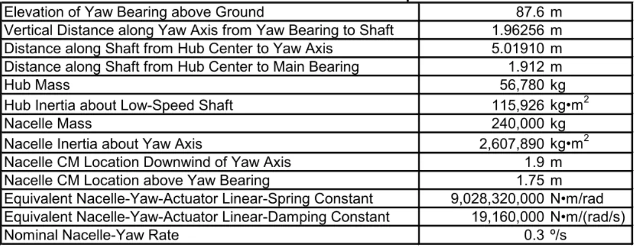
Table 4-1 summarizes the nacelle and hub properties discussed in this section.
Table 4-1. Nacelle and Hub Properties
Elevation of Yaw Bearing above Ground
87.6 m
Vertical Distance along Yaw Axis from Yaw Bearing to Shaft
1.96256 m
Distance along Shaft from Hub Center to Yaw Axis
5.01910 m
Distance along Shaft from Hub Center to Main Bearing
1.912 m
Hub Mass
56,780 kg
Hub Inertia about Low-Speed Shaft
115,926
kg•m
2Nacelle Mass
240,000 kg
Nacelle Inertia about Yaw Axis
2,607,890
kg•m
2Nacelle CM Location Downwind of Yaw Axis
1.9 m
Nacelle CM Location above Yaw Bearing
1.75 m
Equivalent Nacelle-Yaw-Actuator Linear-Spring Constant
9,028,320,000
N•m/rad
Equivalent Nacelle-Yaw-Actuator Linear-Damping Constant
19,160,000
N•m/(rad/s)
5 Drivetrain Properties
We specified the NREL 5-MW baseline wind turbine to have the same rated rotor speed (12.1
rpm), rated generator speed (1173.7 rpm), and gearbox ratio (97:1) as the REpower 5M machine.
The gearbox was assumed be a typical multiple-stage gearbox but with no frictional losses—a
requirement of the preprocessor functionality in FAST for creating ADAMS models [11]. The
electrical efficiency of the generator was taken to be 94.4%. This was chosen to be roughly the
same as the total mechanical-to-electrical conversion loss used by the DOWEC turbine at rated
power—that is, the DOWEC turbine had about 0.35 MW of power loss at about 6.25 MW of
aerodynamic power (from Figure 15, page 24 of Ref. [14]). The generator inertia about the
high-speed shaft was taken to be 534.116 kg
•
m
2
, which is the same equivalent low-speed shaft
generator inertia used in the DOWEC study (i.e., 5,025,500 kg
•
m
2
from page 36 of Ref. [14]).
The driveshaft was taken to have the same natural frequency as the RECOFF turbine model and
a structural-damping ratio—associated with the free-free mode of a drivetrain composed of a
rigid generator and rigid rotor—of 5% critical. This resulted in an equivalent driveshaft
linear-spring constant of 867,637,000 N
•
m/rad and a linear-damping constant of 6,215,000 N
•
m/(rad/s).
The high-speed shaft brake was assumed to have the same ratio of maximum brake torque to
maximum generator torque and the same time lag as used in the DOWEC study (from page 29 of
Ref. [14]). This resulted in a fully deployed high-speed shaft brake torque of 28,116.2 N
•
m and
a time lag of 0.6 s. This time lag is the amount of time it takes for the brake to fully engage once
deployed. The FAST and ADAMS models employ a simple linear ramp from nothing to full
braking over the 0.6-s period.
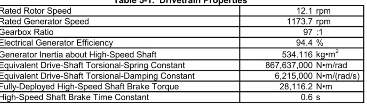
Table 5-1 summarizes the drivetrain properties discussed in this section.
Table 5-1. Drivetrain Properties
Rated Rotor Speed
12.1 rpm
Rated Generator Speed
1173.7 rpm
Gearbox Ratio
97 :1
Electrical Generator Efficiency
94.4 %
Generator Inertia about High-Speed Shaft
534.116
kg•m
2Equivalent Drive-Shaft Torsional-Spring Constant
867,637,000
N•m/rad
Equivalent Drive-Shaft Torsional-Damping Constant
6,215,000
N•m/(rad/s)
Fully-Deployed High-Speed Shaft Brake Torque
28,116.2
N•m
6 Tower Properties
The properties of the tower for the NREL offshore 5-MW baseline wind turbine will depend on
the type support structure used to carry the rotor-nacelle assembly. The type of support structure
will, in turn, depend on the installation site, whose properties vary significantly through
differences in water depth, soil type, and wind and wave severity. Offshore support-structure
types include fixed-bottom monopiles, gravity bases, and space-frames—such as tripods,
quadpods, and lattice frames (e.g., “jackets”)—and floating structures. This section documents
the tower properties for the equivalent land-based version of the NREL 5-MW baseline wind
turbine. These properties provide a basis with which to design towers for site-specific offshore
support structures. For example, different types of offshore support structures for the NREL
5-MW baseline wind turbine have been designed for—and investigated in—separate phases of the
OC3 project [13,25].
We based the distributed properties of the land-based tower for the NREL 5-MW baseline wind
turbine on the base diameter (6 m) and thickness (0.027 m), top diameter (3.87 m) and thickness
(0.019 m), and effective mechanical steel properties of the tower used in the DOWEC study (as
given in Table 9 on page 31 of Ref. [14]). The Young’s modulus was taken to be 210 GPa, the
shear modulus was taken to be 80.8 GPa, and the effective density of the steel was taken to be
8,500 kg/m
3
. The density of 8,500 kg/m
3
was meant to be an increase above steel’s typical value
of 7,850 kg/m
3
to account for paint, bolts, welds, and flanges that are not accounted for in the
tower thickness data. The radius and thickness of the tower were assumed to be linearly tapered
from the tower base to tower top. Because the REpower 5M machine had a larger tower-top
mass than the DOWEC wind turbine, we scaled up the thickness of the tower relative to the
values given earlier in this paragraph to strengthen the tower. We chose an increase of 30% to
ensure that the first fore-aft and side-to-side tower frequencies were placed between the one- and
three-per-rev frequencies throughout the operational range of the wind turbine in a Campbell
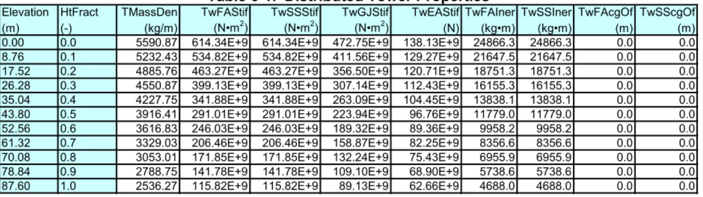
diagram. Table 6-1 gives the resulting distributed tower properties.
The entries in the first column, “Elevation,” are the vertical locations along the tower centerline
relative to the tower base. “HtFract” is the fractional height along the tower centerline from the
tower base (0.0) to the tower top (1.0). The rest of columns are similar to those described for the
distributed blade properties presented in Table 2-1.
The resulting overall (integrated) tower mass is 347,460 kg and is centered at 38.234 m along the
Table 6-1. Distributed Tower Properties
Elevation HtFract
TMassDen
TwFAStif
TwSSStif
TwGJStif
TwEAStif TwFAIner TwSSIner TwFAcgOf TwSScgOf
(m)
(-)
(kg/m)
(N•m
2)
(N•m
2)
(N•m
2)
(N)
(kg•m)
(kg•m)
(m)
(m)
0.00
0.0
5590.87 614.34E+9 614.34E+9 472.75E+9 138.13E+9 24866.3 24866.3
0.0
0.0
8.76
0.1
5232.43 534.82E+9 534.82E+9 411.56E+9 129.27E+9 21647.5 21647.5
0.0
0.0
17.52
0.2
4885.76 463.27E+9 463.27E+9 356.50E+9 120.71E+9 18751.3 18751.3
0.0
0.0
26.28
0.3
4550.87 399.13E+9 399.13E+9 307.14E+9 112.43E+9 16155.3 16155.3
0.0
0.0
35.04
0.4
4227.75 341.88E+9 341.88E+9 263.09E+9 104.45E+9 13838.1 13838.1
0.0
0.0
43.80
0.5
3916.41 291.01E+9 291.01E+9 223.94E+9
96.76E+9 11779.0 11779.0
0.0
0.0
tower centerline above the ground. This result follows directly from the overall tower height of
87.6 m.
We specified a structural-damping ratio of 1% critical in all modes of the isolated tower (without
the rotor-nacelle assembly mass present), which corresponds to the values used in the DOWEC
study (from page 21 of Ref. [14]).
Table 6-2 summarizes the undistributed tower properties discussed in this section.
Table 6-2. Undistributed Tower Properties
Height above Ground
87.6 m
Overall (Integrated) Mass
347,460 kg
CM Location (w.r.t. Ground along Tower Centerline)
38.234 m
7 Baseline Control System Properties
For the NREL 5-MW baseline wind turbine, we chose a conventional variable-speed, variable
blade-pitch-to-feather configuration. In such wind turbines, the conventional approach for
controlling power-production operation relies on the design of two basic control systems: a
generator-torque controller and a full-span rotor-collective blade-pitch controller. The two
control systems are designed to work independently, for the most part, in the below-rated and
above-rated wind-speed range, respectively. The goal of the generator-torque controller is to
maximize power capture below the rated operation point. The goal of the blade-pitch controller
is to regulate generator speed above the rated operation point.
We based the baseline control system for the NREL 5-MW wind turbine on this conventional
design approach. We did not establish additional control actions for nonpower-production
operations, such as control actions for normal start-up sequences, normal shutdown sequences,
and safety and protection functions. Nor did we develop control actions to regulate the
nacelle-yaw angle. (The nacelle-nacelle-yaw control system is generally neglected within aero-servo-elastic
simulation because its response is slow enough that it does not generally contribute to large
extreme loads or fatigue damage.)
We describe the development of our baseline control system next, including the
control-measurement filter (Section 7.1), the generator-torque controller (Section 7.2), the blade-pitch
controller (Section 7.3), and the blade-pitch actuator (Section 7.4). Section 7.5 shows how these
systems are put together in the overall integrated control system.
7.1 Baseline Control-Measurement Filter
As is typical in utility-scale multimegawatt wind turbines, both the generator-torque and
blade-pitch controllers use the generator speed measurement as the sole feedback input. To mitigate
high-frequency excitation of the control systems, we filtered the generator speed measurement
for both the torque and pitch controllers using a recursive, single-pole low-pass filter with
exponential smoothing [30]. The discrete-time recursion (difference) equation for this filter is
[ ]
(
)
[ ]
[
]
y n
= −
1
α
u n
+
α
y n 1
−
,
(7-1)
with
s c 2 T fe
πα
=
−,
(7-2)
where
y
is the filtered generator speed (output measurement),
u
is the unfiltered generator speed
(input),
α
is the low-pass filter coefficient,
n
is the discrete-time-step counter,
T
s
is the discrete
time step, and
f
c
is the corner frequency.
or
[
] [ ]
x n 1
+ =
y n
,
(7-3b)
one can derive a discrete-time state-space representation of this filter:
[
]
[ ]
[ ]
[ ]
dd[ ]
dd[ ]
x n 1
A x n B u n
y n C x n D u n
+ =
+
=
+
,
(7-4)
where
A
d=
α
is the discrete-time state matrix,
B
d= −
1
α
is the discrete-time input matrix,
dC
=
α
is the discrete-time output state matrix, and
D
d= −
1
α
is the discrete-time input
transmission matrix.
The state-space representation of Eq. (7-4) is useful for converting the filter into other forms,
such as transfer-function form or frequency-response form [31].
We set the corner frequency (the -3 dB point in Figure 7-1) of the low-pass filter to be roughly
one-quarter of the blade’s first edgewise natural frequency (see Section 9) or 0.25 Hz. For a
discrete time step of 0.0125 s, the frequency response of the resulting filter is shown in the Bode
plot of Figure 7-1.
We chose the recursive, single-pole filter for its simplicity in implementation and effectiveness
-18
-15
-12
-9
-6
-3
0
0.01
0.10
1.00
Frequency, Hz
M
agni
tude
, dB
-90
-75
-60
-45
-30
-15
0
0.01
0.10
1.00
Frequency, Hz
Ph
ase,
in the time domain. The drawbacks to this filter are its gentle roll-off in the stop band (-6
dB/octave) and the magnitude and nonlinearity of its phase lag in the pass band [30]. We
considered other linear low-pass filters, such as Butterworth, Chebyshev, Elliptic, and Bessel
filters because of their inherent advantages relative to the chosen filter. Like the chosen filter, a
Butterworth filter has a frequency response that is flat in the pass band, but the Butterworth filter
offers steeper roll-off in the stop band. Chebyshev filters offer even steeper roll-off in the stop
band at the expense of equalized-ripple (equiripple) in the pass band (Type 1) or stop band (Type
2), respectively. Elliptic filters offer the steepest roll-off of any linear filter, but have equiripple
in both the pass and stop bands. Bessel filters offer the flattest group delay (linear phase lag) in
the pass band. We designed and tested examples of each of these other low-pass filter types,
considering state-space representations of up to fourth order (four states). None were found to
give superior performance in the overall system response, however, so they did not warrant the
added complexity of implementation.
7.2 Baseline Generator-Torque Controller
The generator torque is computed as a tabulated function of the filtered generator speed,
incorporating five control regions: 1, 1½, 2, 2½, and 3. Region 1 is a control region before cut-in
wind speed, where the generator torque is zero and no power is extracted from the wind; instead,
the wind is used to accelerate the rotor for start-up. Region 2 is a control region for optimizing
power capture. Here, the generator torque is proportional to the square of the filtered generator
speed to maintain a constant (optimal) tip-speed ratio. In Region 3, the generator power is held
constant so that the generator torque is inversely proportional to the filtered generator speed.
Region 1½, a start-up region, is a linear transition between Regions 1 and 2. This region is used
to place a lower limit on the generator speed to limit the wind turbine’s operational speed range.
Region 2½ is a linear transition between Regions 2 and 3 with a torque slope corresponding to
the slope of an induction machine. Region 2½ is typically needed (as is the case for my 5-MW
turbine) to limit tip speed (and hence noise emissions) at rated power.
We found the peak of the power coefficient as a function of the tip-speed ratio and blade-pitch
surface by running FAST with AeroDyn simulations at a number of given rotor speeds and a
number of given rotor-collective blade-pitch angles at a fixed wind speed of 8 m/s. From these
simulations, we found that the peak power coefficient of 0.482 occurred at a tip-speed ratio of
7.55 and a rotor-collective blade-pitch angle of 0.0
˚. With the 97:1 gearbox ratio, this resulted in
an optimal constant of proportionality of 0.0255764 N
•
m/rpm
2
in the Region 2 control law. With
the rated generator speed of 1173.7 rpm, rated electric power of 5 MW, and a generator
efficiency of 94.4%, the rated mechanical power is 5.296610 MW and the rated generator torque
is 43,093.55 N
•
m. We defined Region 1½ to span the range of generator speeds between 670
rpm and 30% above this value (or 871 rpm). The minimum generator speed of 670 rpm
corresponds to the minimum rotor speed of 6.9 rpm used by the actual REpower 5M machine
[26]. We took the transitional generator speed between Regions 2½ and 3 to be 99% of the rated
generator speed, or 1,161.963 rpm. The generator-slip percentage in Region 2½ was taken to be
10%, in accordance with the value used in the DOWEC study (see page 24 of Ref. [14]). Figure
7-2 shows the resulting generator-torque versus generator speed response curve.
Because of the high intrinsic structural damping of the drivetrain, we did not need to incorporate
a control loop for damping drivetrain torsional vibration in our baseline generator-torque
controller.
We did, however, place a conditional statement on the generator-torque controller so that the
torque would be computed as if it were in Region 3—regardless of the generator speed—
whenever the previous blade-pitch-angle command was 1º or greater. This results in improved
output power quality (fewer dips below rated) at the expense of short-term overloading of the
generator and the gearbox. To avoid this excessive overloading, we saturated the torque to a
maximum of 10% above rated, or 47,402.91 N
•
m. We also imposed a torque rate limit of 15,000
N
•
m/s. In Region 3, the blade-pitch control system takes over.
7.3 Baseline Blade-Pitch Controller
In Region 3, the full-span rotor-collective blade-pitch-angle commands are computed using
gain-scheduled proportional-integral (PI) control on the speed error between the filtered generator
speed and the rated generator speed (1173.7 rpm).
We designed the blade-pitch control system using a simple single-degree-of-freedom
(single-DOF) model of the wind turbine. Because the goal of the blade-pitch control system is to
regulate the generator speed, this DOF is the angular rotation of the shaft. To compute the
required control gains, it is beneficial to examine the equation of motion of this single-DOF
system. From a simple free-body diagram of the drivetrain, the equation of motion is
(
2)
(
)
Aero Gear Gen Rotor Gear Gen
d
0 DrivetrainT
N T
I
N
I
I
dt
Ω
∆Ω
∆Ω
−
=
+
+
=
,
(7-5)
0
10,000
20,000
30,000
40,000
50,000
0
200
400
600
800
1,000
1,200
1,400
Generator Speed, rpm
G
en
er
at
or
T
or
qu
e,
N
•m
Optimal
Variable-Speed Controller
Region 1 1½ 2 2½
► 3
where
T
Aero
is the low-speed shaft aerodynamic torque,
T
Gen
is the high-speed shaft generator
torque,
N
Gear
is the high-speed to low-speed gearbox ratio,
I
Drivetrain
is the drivetrain inertia cast to
the low-speed shaft,
I
Rotor
is the rotor inertia,
I
Gen
is the generator inertia relative to the
high-speed shaft,
Ω
0is the rated low-speed shaft rotational speed,
∆Ω
is the small perturbation of
low-speed shaft rotational speed about the rated speed,
∆Ω
is the low-speed shaft rotational
acceleration, and
t
is the simulation time.
Because the generator-torque controller maintains constant generator power in Region 3, the
generator torque in Region 3 is inversely proportional to the generator speed (see Figure 7-2), or
(
)
0 Gen Gear GearP
T
N
N
Ω
Ω
=
,
(7-6)
where
P
0
is the rated mechanical power and
Ω
is the low-speed shaft rotational speed.
Similarly, assuming negligible variation of aerodynamic torque with rotor speed, the
aerodynamic torque in Region 3 is
( )
(
0)
Aero 0P ,
T
θ
θ Ω
Ω
=
,
(7-7)
where
P
is the mechanical power and
θ
is the full-span rotor-collective blade-pitch angle.
Using a first-order Taylor series expansion of Eqs. (7-6) and (7-7), one can see that
0 0 Gen 2 Gear 0 Gear 0
P
P
T
N
Ω
N
Ω
∆Ω
≈
−
(7-8)
and
0 Aero 0 0P
1
P
T
∆θ
Ω
Ω
θ
∂
≈
+
∂
,
(7-9)
where
∆θ
is a small perturbation of the blade-pitch angles about their operating point. With
proportional-integral-derivative (PID) control, this is related to the rotor-speed perturbations by
t
P Gear I Gear D Gear
0