Image-Based 3D Photography using Opacity Hulls
Wojciech Matusik∗ Hanspeter Pfister† Addy Ngan∗ Paul Beardsley† Remo Ziegler† Leonard McMillan∗
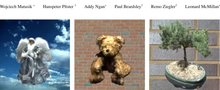
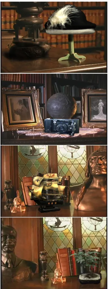
Figure 1:Renditions of acquired objects with a mixture of highly specular and fuzzy materials.
Abstract
We have built a system for acquiring and displaying high quality graphical models of objects that are impossible to scan with tradi-tional scanners. Our system can acquire highly specular and fuzzy materials, such as fur and feathers. The hardware set-up consists of a turntable, two plasma displays, an array of cameras, and a ro-tating array of directional lights. We use multi-background matting techniques to acquire alpha mattes of the object from multiple view-points. The alpha mattes are used to construct anopacity hull. The opacity hull is a new shape representation, defined as the visual hull of the object with view-dependent opacity. It enables visualization of complex object silhouettes and seamless blending of objects into new environments. Our system also supports relighting of objects with arbitrary appearance using surface reflectance fields, a purely image-based appearance representation. Our system is the first to acquire and render surface reflectance fields under varying illumi-nation from arbitrary viewpoints. We have built three generations of digitizers with increasing sophistication. In this paper, we present our results from digitizing hundreds of models.
CR Categories: I.3.2 [Computer Graphics]: Picture/Image Generation—Digitizing and Scanning, Viewing Algorithms;
Keywords: Image-based rendering, 3D photography.
∗MIT, Cambridge, MA.
Email: [wojciech,addy,mcmillan]@graphics.lcs.mit.edu †MERL, Cambridge, MA.
Email: [pfister,beardsley,ziegler]@merl.com
1
Introduction
Creating 3D models manually is time consuming and creates a bot-tleneck for many practical applications. It is both difficult to model complex shapes and to recreate complex object appearance using standard parametric reflectance models. Not surprisingly, tech-niques to create 3D models automatically by scanning real objects have greatly increased in significance. An ideal system would ac-quire an object automatically and construct a detailed shape and appearance model sufficient to place the synthetic object in an arbi-trary environment with new illumination.
Although there has been much recent work towards this goal, no system to date fulfills all these requirements. Most current acquisi-tion systems require substantial manual involvement. Many meth-ods, including most commercial systems, focus on capturing accu-rate shape, but neglect accuaccu-rate appearance capture. Even when the reflectance properties of 3D objects are captured they are fitted to parametric BRDF models. This approach fails to represent com-plex anisotropic BRDFs and does not model important effects such as inter-reflections, self-shadowing, translucency, and subsurface scattering. There have also been a number of image-based tech-niques to acquire and represent complex objects. But all of them have some limitations, such as lack of a 3D model, static illumina-tion, or rendering from few viewpoints.
We have developed an image-based 3D photography system that comes substantially closer to the ideal system outlined above. It is very robust and capable of fully capturing 3D objects that are diffi-cult if not impossible to scan with existing scanners (see Figure 1). It automatically creates object representations that produce high quality renderings from arbitrary viewpoints, either under fixed or novel illumination. The system is built from off-the-shelf compo-nents. It uses digital cameras, leveraging their rapid increase in quality and decrease in cost. It is easy to use, has simple set-up and calibration, and scans objects that fit within a one cubic foot volume. The acquired objects can be accurately composited into synthetic scenes.
After a review of previous work, we give an overview of our system in Section 3. In Section 4 we present theopacity hull, a new shape representation especially suited for objects with com-plex small-scale geometry. Section 5 describes surface reflectance
fields, an appearance representation that allows us to render objects with arbitrary reflectance properties under new illumination. Sec-tion 6 describes our novel data structure that parameterizes surface light fields and surface reflectance fields onto point-sampled opac-ity hulls. In Section 7 we show how to interpolate surface light fields and surface reflectance fields to generate views from arbi-trary positions. Section 8 presents results, including quantitative evaluations.
2
Previous Work
There are many approaches for acquiring high quality 3D shape from real-world objects, including contact digitizers, passive stereo depth-extraction, and active light imaging systems. Passive digi-tizers are not robust in cases where the object being digitized does not have sufficient texture. Nearly all passive methods assume that the BRDF is Lambertian or does not vary across the surface. They often fail in the presence of subsurface scattering, inter-reflections, or surface self-shadowing.
Active light systems, such as laser range scanners, are very pop-ular and have been employed to acquire large models [Levoy et al. 2000; Rushmeier et al. 1998]. All active light systems place restric-tions on the types of materials that can be scanned, as discussed in detail in [Hawkins et al. 2001]. They also require a registration step to align separately acquired scanned meshes [Turk and Levoy 1994; Curless and Levoy 1996] or to align the scanned geometry with separately acquired texture images [Bernardini et al. 2001]. Filling gaps due to missing data is often necessary as well. Systems have been constructed where multiple lasers are used to acquire a surface color estimate along the line of sight of the imaging sys-tem. However, this is not useful for capturing objects in realistic illumination environments.
To acquire objects with arbitrary materials we use an image-based modeling and rendering approach. Image-image-based represen-tations have the advantage of capturing and representing an object regardless of the complexity of its geometry and appearance.
Early image-based methods [McMillan and Bishop 1995; Chen and Williams 1993] allowed for navigation within a scene using correspondence information. Light field methods [Levoy and Han-rahan 1996; Gortler et al. 1996] achieve similar results without geometric information, but with an increased number of images. Gortler et al. [1996] combine the best of these methods by includ-ing a visual hull of the object for improved ray interpolation. These methods assume static illumination and therefore cannot accurately render objects into new environments.
An intermediate between purely model-based and purely image-based methods is the view-dependent texture mapping systems de-scribed by Pulli et al. [1997] and Debevec et al. [1998; 1996]. These systems combine simple geometry and sparse texture data to accurately interpolate between the images. These methods are extremely effective despite their approximate 3D shapes, but they have some limitations for highly specular surfaces due to the rela-tively small number of textures.
As noted in [Debevec et al. 1998], surface light fields [Miller et al. 1998; Wood et al. 2000; Nishino et al. 1999a; Nishino et al. 1999b; Chen et al. 2002] can be viewed as a more general and more efficient representation of view-dependent texture maps. Wood et al. [2000] store light field data on accurate high-density geometry, whereas Nishino et al. [1999a] use a coarser triangular mesh for ob-jects with low geometric complexity. Chen at al. [2002] are using a decomposition of surface light fields that can be efficiently ren-dered on modern graphics hardware. Surface light fields are capa-ble of reproducing important global effects such as inter-reflections and self-shadowing. Our system is capable of surface light field acquisition and rendering.
Images generated from a surface light field always show the ob-ject under a fixed lighting condition. To overcome this limitation, inverse rendering methods estimate the surface BRDF from images and geometry of the object. To achieve a compact BRDF represen-tation, most methods fit a parametric reflection model to the image data [Sato et al. 1997; Yu et al. 1999; Lensch et al. 2001]. Sato et al.[1997] and Yu et al. [1999] assume that the specular part of the BRDF is constant over large regions of the object, while the diffuse component varies more rapidly. Lensch et al. [2001] partition the objects into patches and estimate a set of basis BRDFs per patch.
Simple parametric BRDFs, however, are incapable of represent-ing the wide range of effects seen in real scenes. As observed in [Hawkins et al. 2001], objects featuring glass, fur, hair, cloth, leaves, or feathers are very challenging or impossible to represent this way. As we will show in Section 8, reflectance functions for points in highly specular or self-shadowed areas are very complex and cannot easily be approximated using smooth basis functions. In our work we make no assumptions about the reflection property of the material we are scanning.
An alternative is to use image-based, non-parametric represen-tations for object reflectance. Marschner et al. [1999] use a tabu-lar BRDF representation and measure the reflectance properties of convex objects using a digital camera. Their method is restricted to objects with a uniform BRDF, and they incur problems with ge-ometric errors introduced by 3D range scanners. Georghiades et al. [1999] apply image-based relighting to human faces by assum-ing that the surface reflectance is Lambertian.
More recent approaches [Malzbender et al. 2001; Debevec et al. 2000; Hawkins et al. 2001; Koudelka et al. 2001] use image databases to relight objects from a fixed viewpoint without acquir-ing a full BRDF. Debevec et al. [2000] define thereflectance field
of an object as the radiant light from a surface under every pos-sible incident field of illumination. They use a light stage with few fixed camera positions and a rotating light to acquire the re-flectance field of a human face [Debevec et al. 2000] or of cultural artifacts [Hawkins et al. 2001]. The polynomial texture map system described in [Malzbender et al. 2001] uses a similar technique for objects with approximately planar geometry and diffuse reflectance properties. Koudelka et al. [2001] use essentially the same method as [Debevec et al. 2000] to render objects with arbitrary appearance. These reflectance field approaches are limited to renderings from a single viewpoint.
3
System Overview
3.1 Modeling ApproachOur system uses a variant of the image-based visual hull (IBVH) [Matusik et al. 2000] as the underlying geometric model. The IBVH can be computed robustly using active backlighting. We augment the IBVH with view-dependent opacity to accurately rep-resent complex silhouette geometry, such as hair. We call this new shape representation the opacity hull. To construct the opacity hull we use the multi-background matting techniques similar to Smith et al. [1996].
Our system can acquire a surface light field of the object. It can also acquire reflectance fields of the object from multiple view-points. We call this representation a surface reflectance field, be-cause the data is parameterized on the surface of the visual hull of the object. Surface reflectance fields can be rendered from any viewpoint under new illumination. We use images from the same viewpoints to compute the opacity hull and the surface reflectance field. This avoids any registration inaccuracies and has proven to be extremely robust.
Laurentini [1994] introduced the visual hull as the maximal vol-ume that is consistent with a given set of silhouettes. The visual hull
cannot represent surface concavities. Yet, due to its hull property, it provides a conservative estimate of an object’s structure. The opacity hull and surface reflectance field extend the utility of vi-sual hull considerably by faithfully representing complex silhou-ettes and materials.
Instead of relying on accurate geometry, our representation re-lies heavily upon acquired radiance information to produce accu-rate renderings of the object. We can adaptively acquire more ages for objects with concavities or high specularity, and fewer im-ages for objects with simple geometry and mostly diffuse surfaces. Naturally, this approach is not useful for applications where geo-metric fidelity is required. In this paper we demonstrate that the combination of opacity hull geometry and the image-based surface reflectance field leads to an effective representation for rendering applications. Our system is capable of acquiring and rendering ob-jects that are fuzzy, highly specular, or that contain any mixture of materials.
3.2 Hardware Set-Up
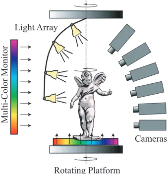
Figure 2 shows an overview of our hardware set-up. Objects are placed on a plasma monitor that is mounted onto a rotating turntable. An array of light sources is mounted on an overhead turntable. The lights are spaced roughly equally along the elevation angle of the hemisphere. During object scanning, the lights can be
Multi-Color Monitor
Light Array
Cameras
Rotating Platform
Figure 2: Our 3D digitizing system combines both active and pas-sive imaging methods. Objects are rotated on a turntable while im-ages are acquired. Plasma monitors are used to extract high quality alpha mattes. An overhead array of light sources can be rotated to acquire surface reflectance fields.
fixed, rotate around the object for a fixed point of view, or made to rotate with the object. Six video cameras are pointed at the ob-ject from various angles. To facilitate consistent back lighting we mount the cameras roughly in the same vertical plane. A second plasma monitor is placed directly opposite of the cameras.
Figure 3 shows a picture of our third-generation scanner. The two plasma monitors have a resolution of 1024×768 pixels. We currently use six QImaging QICAM cameras with 1360×1036 pixel color CCD imaging sensors. The cameras are photometrically calibrated. They are connected via FireWire to a 2 GHz Pentium-4 PC with 1 GB of RAM. We alternatively use 15 mm or 8 mm
Figure 3:Photograph of our digitizing system.
C-mount lenses, depending on the size of the acquired object. The cameras are able to acquire full resolution RGB images at 11 frames per second.
The light array holds four to six directional light sources. Each light uses a 32 Watt HMI Halogen lamp and a parabolic reflector to approximate a directional light source at infinity. The lights are controlled by an electronic switch and individual dimmers. The dimmers are set once such that the image sensor is not oversaturated for viewpoints where the lights are directly visible.
In many ways, our set-up is similar to the enhanced light stage that has been proposed as future work in [Hawkins et al. 2001]. A key difference is that our system uses multicolor backlights for alpha matte extraction and construction of the opacity hull. As we will show, the availability of approximate geometry and view-dependent alpha greatly extends the class of models that can be captured.
3.3 Data Acquisition Process
Calibration: The scanning sequence starts by placing the object onto the turntable and, if necessary, adjusting the position and aper-ture of the cameras. If any camera adjustments are required, we must first acquire images of a known calibration object, a patterned cube in our case. An image of the calibration target is taken from each of the viewpoints. Intrinsic and extrinsic camera parameters are computed using a special calibration procedure for turntable systems with multiple cameras [Beardsley 2002]. Calibration can be computed reliably given the fixed rotation axis and the large numbers of images.
Reference images: Next, the plasma monitors are turned on and we acquire images of patterned backdrops used for multi-background matting. For each viewpoint, each patterned back-drop is photographed alone without the foreground object. As in [Zongker et al. 1999], we call these images thereference images. Reference images only have to be acquired once after calibration. They are stored and used for subsequent object scans.
Object images: The object is then put on the turntable and a sequence of images is automatically acquired. The number of turntable positions is user specified and depends on the object (see Section 8). During this first rotation, both plasma monitors illu-minate the object from below and behind with the patterned back-drops. As in [Zongker et al. 1999], we call the images of the fore-ground object in front of the backdropsobject images. The object images and reference images are used to compute alpha mattes and the opacity hull as described in Section 4. We depend on good re-peatability of the turntables to ensure that the reference images and the object images are well registered.
Radiance images:We then switch off the plasma monitors and turn on one or more directional lights of the array. We found that we get best results when using additional fill light to avoid dark shadows and high contrast in the images. We avoid specular reflec-tions from the monitors by covering the vast majority of the display surface with black felt without upsetting the object position. We acquire a set ofradiance imagesof the illuminated object during the second rotation of the turntable. The radiance images are used for surface light field rendering. The directional lights can be fixed or made to rotate with the object. The coupled rotation case leads to greater coherence of radiance samples in each surface point.
Reflectance images: If we want to relight the acquired object, we acquire an additional set of images used to construct the surface reflectance field. The array of lights is rotated around the object. For each rotation position, each light in the light array is sequen-tially turned on and an image is captured with each camera. We use four lights and typically increment the rotation angle by 24◦ for a total of 4×15 images for each camera position. This procedure is repeated for all viewpoints. We call the set of all images the re-flectance images. They are used to construct the surface reflectance field as described in Section 5.
HDR images:All radiance and reflectance images are captured using a high dynamic range technique similar to that of Debevec et al. [1997]. Since raw output from the CCD array of the cameras is available, the relationship between exposure time and radiance val-ues is linear over most of the operating range. For each viewpoint, we take four pictures with exponentially increasing exposure times and use a least squares linear fit to determine the response line. Our imager has 10 bits of precision. Due to non-linear saturation effects at the extreme ends of the scale we only use values in the range of 5 to 1000 in our least squares computation. We can ignore the DC offset of this calculation, which was small for our cameras1, and
store only the slope of the response line as one floating point num-ber per pixel. This image representation allows for the specification of a desired exposure interval at viewing time.
The next section describes our procedure to compute alpha mat-tes and how we use them to compute the opacity hull of the object.
4
The Opacity Hull
4.1 Acquiring Alpha MattesTo construct the image-based visual hull on which we parameterize the opacity hull, we extract silhouette images from various view-points. Earlier versions of our system use fluorescent lights to ac-quire silhouette views. Backlighting is a common segmentation ap-proach that is often used in commercial two-dimensional machine vision systems. The backlights saturate the image sensor in areas where they are visible. We then threshold the silhouette images to establish a binary segmentation for the object.
However, binary thresholding is not accurate enough for objects with small silhouette features, such as hair. It also does not per-mit sub-pixel accurate compositing of the objects into new
environ-1DC offsets are due to thermal and fixed pattern noise of the imager.
ments. An additional problem is colorspill[Smith and Blinn 1996], the reflection of backlight on the foreground object. Spill typically happens near object silhouettes because the Fresnel effect increases the specularity of materials near grazing angles. With a single color active backlight, spill is particularly prominent for highly specular surfaces, such as metal or ceramics.
We use a variant of the multi-background matting technique of Smith et al. [1996] to solve these problems. We acquire alpha mat-tes of the object from each viewpoint. An alpha matte of a fore-ground object can be extracted by imaging the object against two background images with different colors. We display the following sinusoidal background patterns on the plasma monitors:
Ci(x,y,n) = (1+nsin(
2π(x+y)
λ +iπ3))×127. (1)
Ci(x,y,n)is the intensity of color channeli=0,1,2 at pixel location
(x,y). To maximize the per-pixel difference between the two back-drops, the patterns are phase shifted by 180◦ (n=−1 or 1). The user defines the period of the sinusoidal stripes with the parameter
λ.
Using the multi-background matting equation from [Smith and Blinn 1996], the per-pixel object alphaαois computed using
sum-mation over all color channels as:
αo=1−∑i=r,g,b(
On−On¯)(Rn−Rn¯)
∑i=r,g,b(Rn−Rn¯)2 ,
(2)
whereRnandRn¯ are per-pixel background colors of the reference
images, andOnandOn¯are per-pixel foreground colors of the object
images forn=±1, respectively.
If we measure the same color at a pixel both with and without the object for each background, Equation (2) equals zero. This cor-responds to a pixel that maps straight through from the background to the sensor. The phase shifts in the color channels of Equation (1) assures that the denominator of Equation (2) is never zero. The si-nusoidal pattern reduces the chance that a pixel color observed due to spill matches the pixel color of the reference image. Neverthe-less, we still observed spill errors for highly specular objects, such as the teapot or the bonsai pot.
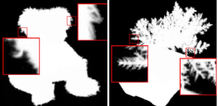
To reduce these errors we apply the same procedure multiple times, each time varying the wavelengthλ of the backdrop pat-terns. For the final alpha matte we store the maximum alpha from all intermediate mattes. We found that acquiring three intermedi-ate alpha mattes with relatively prime periodsλ=27,40 and 53 is sufficient. The overhead of taking the additional images is small, and we need to store only the final alpha matte. Figure 4 shows two alpha mattes acquired with our method. We found that in practice
Figure 4:Alpha mattes acquired using our backdrops.
this method works very well for a wide variety of objects, including specular and fuzzy materials.
4.2 Opacity Hull Construction
Using the alpha mattes of the object from various viewpoints, we construct the opacity hull. First, we use binary thresholding on the alpha mattes to get binary silhouette images. Theoretically, each pixel withα>0 (i.e., not transparent) belongs to the foreground object. We use a slightly higher threshold because of noise in the system and calibration inaccuracies. We found that a threshold of α >0.05 yields a segmentation that covers all of the object and parts of the background.
The binary silhouettes are then used to construct the image-based visual hull (IBVH) [Matusik et al. 2000]. The IBVH algorithm can be counted on to remove improperly classified foreground regions as long as they are not consistent with all other images. We re-sample the IBVH into a dense set of surface points as described in Section 6. Each point on the visual hull surface is projected onto the alpha mattes to determine its opacity from a particular observed viewpoint.
The opacity hull is similar to a surface light field, but instead of storing radiance it stores opacity values in each surface point. It is useful to introduce the notion of analphasphereA. Ifω is an outgoing direction at the surface point p, thenA(p,ω)is the opacity value seen along directionω.
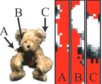
Figure 5 shows the observed alpha values for three surface points on an object for all 6×36 viewpoints. Each pixel has been colored
A
B
C
A B C
Figure 5:Observed alpha values for points on the opacity hull. Red color indicates invisible camera views.
according to its opacity. Black color corresponds toα=0, white color corresponds toα=1, and grey color corresponds to values in between. Red color indicates camera views that are invisible from the surface point.
The functionA is defined over the entire direction sphere. Any physical scanning system acquires only a sparse set of samples of this function. As is done for radiance samples of lumispheres in [Wood et al. 2000], one could estimate a parametric function for
A and store it in each alphasphere. However, as shown in Figure 5, the view-dependent alpha is not smooth and not easily amenable to parametric function fitting. Consequently, we store the acquired al-pha mattes and interpolate between them to render the opacity hull from arbitrary viewpoints (see Section 7).
It is important to keep in mind that the opacity hull is a view-dependent representation. It captures view-view-dependent partial occu-pancy of a foreground object with respect to the background. The view-dependent aspect sets the opacity hull apart from voxel shells, which are frequently used in volume graphics [Udupa and Odhner
1993]. Voxel shells are not able to accurately represent fine silhou-ette features, which is the main benefit of the opacity hull.
Recognizing the importance of silhouettes, Sander et al. [2000] use silhouette clipping to improve the visual appearance of coarse polygonal models. However, their method depends on accurate ometric silhouettes, which is impractical for complex silhouette ge-ometry like fur, trees, or feathers. Opacity hulls are somewhat sim-ilar to the concentric, semi-transparent textured shells that Lengyel et al. [2001] used to render hair and furry objects. They use ge-ometry – called textured fins – to improve the appearance of object silhouettes. A single instance of the fin texture is used on all edges of the object. In contrast, opacity hulls can be looked at as textures with view-dependent alphas for every surface point of the object. They accurately render silhouettes of high complexity using only visual hull geometry.
5
Surface Reflectance Fields
Similar to constructing the opacity hull, we re-parameterize the ac-quired radiance images into rays emitted from surface points on the visual hull. This representation is a surface light field as described by Miller [Miller et al. 1998] and Wood [Wood et al. 2000]. How-ever, our surface light fields are created on the surface of the visual hull rather than on the surface of the object.
Surface light fields can only represent models under the origi-nal illumination. To address this limitation we acquire surface re-flectance fields from multiple viewing positions around the object. Debevec et al. [2000] define the reflectance field under directional illumination as a six-dimensional functionR(P,ωi,ωr). For each
surface pointP, it maps incoming light directionsωito reflected
color values along directionωr. Thus, for each pointPwe have a
four-dimensional functionRP(ωi,ωr).
During acquisition, we sample the four dimensional function
RP(ωi,ωr)from a set of viewpointsΩr and a set of light
direc-tionsΩi. In previous reflectance field approaches [Debevec et al.
2000; Hawkins et al. 2001; Koudelka et al. 2001], the sampling of light directions is dense (e.g.,|Ωi|=64×32 in [Debevec et al. 2000]), but only a single viewpoint is used. In our system, we sam-ple the reflectance field from many directions (|Ωr|=6×36). To limit the amount of data we acquire and store, our system uses a sparse sampling of light directions (|Ωi|=4×15). Thus, our illu-mination environment has to be filtered down substantially, and our re-illumination is accurate only for relatively diffuse surfaces [Ra-mamoorthi and Hanrahan 2001].
Reconstruction of an image from a new viewing direction un-der a new lighting configuration is a two-pass process. First, we reconstruct the images from the original viewpoints under novel illumination. Once we have computed these images, we interpo-late the image data to new viewpoints as described in Section 7. For a particular image from the original viewpoint, it is useful to define a slice of the reflectance field called areflectance function
Rxy(ωi)[Debevec et al. 2000]. It represents how much light is
re-flected toward the camera by pixel(x,y)as a result of illumination from directionωi. We can reconstruct the imageL(x,y)from the
original viewpoint under novel illumination as a weighted linear combination of the light sourcesL(ωi)as follows:
L(x,y) =
∑
ωi
Rxy(ωi)L(ωi)dA(ωi), (3)
wheredA(ωi)is the solid angle covered by each of the original
6
Point-Sampled Data Structure
We use an extended point representation based on the layered depth cube (LDC) tree [Pfister et al. 2000] as our shape model on which we parameterize the view-dependent appearance data. In a pre-process, we compute the octree-based LDC tree from the IBVH. The creation of the LDC tree starts with the sampling of the visual hull from three orthogonal directions. The sampling density de-pends on the model complexity and is user specified. The layered depth images are then merged into a single octree model. Since our visual hulls are generated from virtual orthographic viewpoints, their registration is exact. This merging also insures that the model is uniformly sampled.
Point samples have several benefits for 3D scanning applications. From a modeling point of view, the point-cloud representation elim-inates the need to establish topology or connectivity. This facilitates the fusion of data from multiple sources, as pointed out by [Levoy and Whitted 1985]. They also avoid the difficult task of computing a consistent parameterization of the surface for texture mapping. We found that point models are able to represent complex organic shapes, such as a bonsai tree or a feather, more easily than polyg-onal meshes. In particular, it would be hard to represent the view-dependent opacity values at each point of the opacity hull using polygonal models and texture mapping.
Each surfel (surface element) in the LDC tree stores depth, nor-mal, and a camera-visibility bit vector. The visibility vector stores a value of one for each camera position from which the surfel was visible. It can be quickly computed during IBVH construction us-ing the visibility algorithm described in [Matusik et al. 2000]. Our representation stores all of the acquired radiance and reflectance im-ages with irrelevant information removed. This is accomplished by dividing each source image into 8 by 8 blocks and removing those blocks that lie outside the object’s silhouette. For each image, we compute a simple mask by back-projecting all surfels from which this view is visible. Only the 8 by 8 pixel blocks that contain at least one back-projected surfel are stored. This simple scheme typically reduces the total amount of image data by a factor of five to ten, depending on the geometry of the model.
A relightable model requires more than 20 GB of raw image data. In order to make this data more manageable, we have im-plemented a simple compression scheme for reflectance images. For each original viewpoint, we apply principal component analy-sis (PCA) to corresponding 8 by 8 image blocks across the varying 4×15 illumination directions taken from a common viewpoint. We set a global threshold for the RMS reconstruction error and store a variable number of principal components per block. As shown in Section 8, the average number of components per block is typi-cally four to five. PCA compression typitypi-cally reduces the amount of reflectance data by a factor of 10.
Figure 6 shows a depiction of our data structure for surface re-flectance fields, simplified for clarity. The figure shows the first six PCA images for two original views. These images are com-bined into new radiance images from the same viewpoints under new illumination using the method described in Section 5. During rendering, points on the opacity hull of the object are projected into the radiance images based on their visibility. Each surfel’s color is determined using interpolation among the four closest views. Note that the figure shows the two closest views.
7
Rendering
To render our point-sampled models we use the elliptical weighted average (EWA) surface splatting approach of [Zwicker et al. 2001]. First, the opacity and color of each surfel is interpolated from the ra-diance images as discussed below. A hierarchical forward-warping algorithm projects the surfels onto the screen. A screen space EWA
Relighted View 1 Relighted View 2
PCA Images for View 1 PCA Images for View 2 Relighted Model New View 0 1 2 3 4 5
...
0 1 2 3 4 5...
Figure 6:Data structure for surface reflectance fields.
filter reconstructs the image using the opacity, color, and normal stored per surfel. A modified A-buffer provides order-independent alpha blending and edge anti-aliasing.
To compute the radiance data for novel illumination, we first compute new images from the original reflectance field data us-ing linear combinations as explained in Section 5. For each 8 by 8 pixel block, we compute the linear combination directly on the co-efficients of the PCA basis. Once we have a new set of coco-efficients, we can easily reconstruct the new radiance images from the princi-pal components. This computation is performed for each change of the light configuration.
To interpolate the radiance images of the original viewpoints to arbitrary viewpoints, we use the unstructured lumigraph interpo-lation of Buehler et al. [2001]. For each surfel, we use k-nearest neighbor interpolation to reconstruct view-dependent alpha and ra-diance values. This assures continuous transitions between camera views.
For each frame, we compute the normalized directionrc(i)from
each surfel position to each visible cameraiusing the visibility bit vector and a global array of camera positions. We also compute the normalized viewing directionrvfrom the surfel position to the
center of projection of the current view. We then assign a penalty
p(i) =1−cosθito each visible camera, where cosθi=rc·rv. We
consider only thek=4 cameras with smallest penaltyp(i)when in-terpolating a value. All other cameras are assigned an interpolation weightw(i)of zero. We take care that a particular camera‘s weight falls to zero as it leaves the set of the closest four cameras. We accomplish this by defining an adaptive threshold cosθt=r4·rv,
wherer4is the direction of the surfel to the fourth closest camera.
The blending weightw(i)for each camera is:
w(i) =cosθi−cosθt
1−cosθt
(4)
This weight function has its maximum value of one for cosθi=1,
and it falls off to zero at cosθi=cosθt. To ensure epipole
con-sistency, we multiplyw(i)by 1/p(i). This ensures that rendering the object from original camera viewpoints reproduces exactly the original images. We also normalize allw(i)so that they sum up to one.
8
Results
We have collected a wide range of objects and surface types with our system. We have acquired many difficult surfaces including
Figure 7: A combination of scanned and real objects in real en-vironments. The scanned objects were illuminated using surface reflectance fields.
those of various genuses, with concavities, and with fine scale fea-tures. We have also captured a wide range of materials, including fuzzy and highly specular materials. A variety of different models are shown in Figure 1 and Figure 13. Figure 14 shows a model un-der new illumination. Figure 7 shows several scanned objects com-posited into real environments. We acquired spherical light probe images [Debevec and Malik 1997] at the respective locations to cap-ture the illumination. All objects shown in this paper are rendered from novel viewpoints that are not part of the acquired image se-quence.
For all objects, we use six cameras and 36 turntable positions. We acquire six object images for alpha matting from each view-point (over three λ values with n=±1). All radiance and re-flectance images are acquired in high dynamic range by capturing four frames. For surface light fields, we capture one radiance im-age from each viewpoint for a total of 6×36×(4×1+6) =2160 images. For surface reflectance fields, we acquire reflectance im-ages using 4×15 light directions from each viewpoint for a total of 6×36×(4×(4×15)) +6) =53136 images. The entire dig-itizing process takes about one hour for a surface light field and about 14 hours for a surface reflectance field. The whole process is fully automated without any user intervention. All of our models are created from a single scan.
We resampled all of our visual hull models to 512×512 resolu-tion of the LDC tree. The processing time to segment the images, compute the opacity hull, and build the point-based data structure is less than 10 minutes. The PCA analysis of the surface reflectance field takes about 36 hours on a single PC using non-optimized Mat-lab code. To speed up the PCA computation, we are using multiple PCs to process different image sets in parallel.
In the process of acquiring models, we have made many inter-esting measurements and observations. Figure 8 shows plots of the measured reflectance field data for three surface points on an object. We chose the surfels to be in specular and self-shadowed areas of the object. The dark parts of the plots are attributable to self
shad-A
B
C
D
E
A
B
C
D
E
Figure 8: Measured reflectance function data for several surface points.
owing. The data lacks any characteristics that would make it a good fit to standard parametric BRDF models or function approximation techniques. This is typical for the data we observed.
Figure 9 shows a visualization of the number of PCA compo-nents per 8 by 8 pixel block of the reflectance images from an orig-inal viewpoint. We set the global RMS reconstruction error to be
Figure 9: a) Original view. b) Visualization of number of PCA components per block (Max. = 15, Mean = 5).
within 1% of the average radiance values of all HDR reflectance im-ages. Note that areas with high texture frequency require more com-ponents than areas of similar average color. The maximum number of components for this view is 10, the average is five. This is typical for all of our data.
Figure 10 shows the visual hull, opacity hull, and final composite rendering of a bonsai tree. Notice the coarse shape of the visual hull
b)
c)
d)
a)
Figure 10: a) Photo of the object. b) Rendering using the opacity hull. c) Visual hull. d) Opacity hull.
and the much improved rendition using the opacity hull, despite the fact that their geometry is identical. The opacity hull also allows high quality compositing over complex backgrounds without edge aliasing.
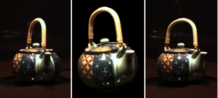
Unstructured lumigraph interpolation for viewpoints other than those seen by reference cameras introduces small artifacts, most notably for specular or concave areas. Figure 11 shows acquired images of an object (Figures 11a and c). Figure 11b shows the object from an intermediate viewpoint. Note that the figure shows only the two closest views, although we use the four closest views for interpolation. As can be seen in the figure, the artifacts are generally small. The animations on the companion videotape show
that the k-nearest neighbor interpolation leads to nice and smooth transitions.
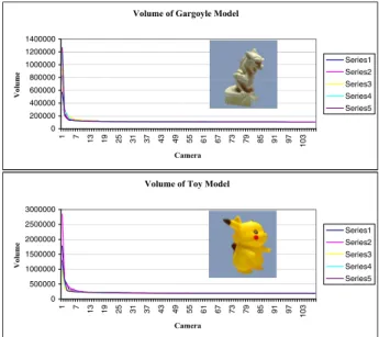
To evaluate the number of images required to compute the visual hull, we instrumented our code to compute the change in volume of orthographic visual hulls as each silhouette is processed. We then randomized the processing order of the images and repeated the IBVH calculation multiple times. The plots shown in Figure 12 illustrate the rather typical behavior. Generally, the visual hull
con-Volume of Gargoyle Model
0 200000 400000 600000 800000 1000000 1200000 1400000 1 7 13 19 25 31 37 43 49 55 61 67 73 79 85 91 97 103 Camera Volume Series1 Series2 Series3 Series4 Series5
Volume of Toy Model
0 500000 1000000 1500000 2000000 2500000 3000000 1 7 13 19 25 31 37 43 49 55 61 67 73 79 85 91 97 103 Camera Volume Series1 Series2 Series3 Series4 Series5
Figure 12:The volume of the visual hull as a function of the number of images used to construct the visual hull.
verges to within 5% of its final volume after processing around 20 images, and seldom is this plateau not reached by 30 images. Collecting data over the entire hemisphere ensures that this volume closely approximates the actual visual hull. This implies that the vi-sual hull processing time can be dramatically reduced by consider-ing fewer images to compute the hull model. However, dense alpha mattes are still important for representing view-dependent opacity. These view-dependent opacities and radiance measurements dra-matically improve the final renderings.
9
Future Work
We are currently working on incorporating environment matting techniques [Zongker et al. 1999] to correctly represent reflection and refraction for transparent objects. We plan to store this view-dependent data using a representation similar to the opacity hull.
In order to preserve the quality of our models, we have applied only minimal lossy compression to the data. Improving on this compression is clearly one of our next goals. Storing the data in 8 by 8 image blocks allows the application of traditional image com-pression tools. The availability of alpha mattes for each image al-lows the application of the shape adaptive compression available in JPEG 2000 and MPEG-4. The temporal coherence of the acquired images should help in achieving high compression ratios. We also plan to use adaptive reconstruction errors for lossy compression of the reflectance field data.
Due to the approximate visual hull shape, our technique has problems in areas of concavities. The lack of accurate geometry can lead to jumping of features over a concavity with a pronounced texture. This could be addressed by improving the geometry us-ing computer vision techniques. Another solution is to use adap-tive sampling by taking more images in areas where the change of
Figure 11:Rendering from arbitrary viewpoints. Left and right: Original images. Middle: Interpolated view.
view-dependent radiance data per surface point is sufficiently non-smooth.
We are investigating real-time rendering methods for our mod-els. Our non-optimized implementation takes about 30 seconds per frame on current PCs. As shown in [Rusinkiewicz and Levoy 2000; Pfister et al. 2000], a point-based representation allows interactive rendering even if the point set is very large. We have already im-plemented an interactive renderer for surface light fields, and we believe we can substantially accelerate the rendering of surface re-flectance fields. Another avenue for future research is the use of graphics accelerators to render our models.
Our scanning hardware currently limits the size of the acquired objects. It also does not allow scanning of faces, people, or dynamic objects. One could imagine extending our approach to hand-held or room size scanners. Major technical difficulties include accurate camera calibration, alpha matte extraction, and controlled illumina-tion. However, we believe there is a spectrum of possible digitizer implementations with varying quality and features based on our ap-proach.
10
Conclusions
We have developed a fully automated and robust 3D photography system optimized for the generation of high quality renderings of objects. The basic premise of our scanning approach is to use large amounts of radiance and opacity information to produce accurate renderings of the object instead of relying on accurate geometry. We have introduced the opacity hull, a new shape representation that stores view-dependent alpha parameterized on the visual hull of the object. Opacity hulls combined with surface reflectance fields allow us to render objects with arbitrarily complex shape and ma-terials under varying illumination from new viewpoints. Avenues for future research include compression, real-time rendering, and improved scanning hardware.
11
Acknowledgments
We would like to thank Chris Buehler, Tom Buehler, and David Tames for helpful discussions and their efforts in producing the video; Bill Yerazunis, Darren Leigh, and Michael Stern for help
with construction of the 3D scanner; Joe Marks for his continu-ing support; the anonymous reviewers for many constructive com-ments; and Jennifer Roderick Pfister for proofreading the paper. Parts of this work were supported by NSF grants CCR-9975859 and EIA-9802220.
References
BEARDSLEY, P. 2002. Calibration of stereo cameras for a turntable 3d scanner. Tech. rep., MERL. TR 2002/20.
BERNARDINI, F., MARTIN, I.,ANDRUSHMEIER, H. 2001. High-quality texture reconstruction from multiple scans.IEEE Trans. on Vis. and Comp. Graph. 7, 4 (Oct.-Dec.), 318–332.
BUEHLER, C., BOSSE, M., MCMILLAN, L., GORTLER, S.,AND
COHEN, M. 2001. Unstructured lumigraph rendering. In
Com-puter Graphics, SIGGRAPH 2001 Proceedings, 425–432.
CHEN, S. E., ANDWILLIAMS, L. 1993. View interpolation for image synthesis. InComputer Graphics, SIGGRAPH 93 Pro-ceedings, 279–288.
CHEN, W.-C., GRZESZCZUK, R.,ANDBOUGUET, J.-Y. 2002. Light field mapping: Efficient representation and hardware ren-dering of surface light fields. InComputer Graphics, To appear in the SIGGRAPH 2002 Proceedings.
CURLESS, B., AND LEVOY, M. 1996. A volumetric method
for building complex models from range images. InComputer
Graphics, SIGGRAPH 96 Proceedings, 303–312.
DEBEVEC, P.,ANDMALIK, J. 1997. Recovering high dynamic range radiance maps from photographs. InComputer Graphics, SIGGRAPH 97 Proceedings, 369–378.
DEBEVEC, P., TAYLOR, C.,ANDMALIK, J. 1996. Modeling and rendering architecture from photographs: A hybrid geometry-and image-based approach. InComputer Graphics, SIGGRAPH 96 Proceedings, 11–20.
DEBEVEC, P., YU, Y., ANDBORSHUKOV, G. 1998. Efficient view-dependent image-based rendering with projective texture-mapping. InProceedings of the 9th Eurographics Workshop on Rendering, 105–116.
DEBEVEC, P., HAWKINS, T., TCHOU, C., DUIKER, H.-P.,
SAROKIN, W., AND SAGAR, M. 2000. Acquiring the
re-flectance field of a human face. InComputer Graphics, SIG-GRAPH 2000 Proceedings, 145–156.
GEORGHIADES, A., BELHUMEUR, P., AND KRIEGMAN, D.
1999. Illumination-based image synthesis: Creating novel im-ages of human faces under differing pose and lighting. In
IEEE Workshop on Multi-View Modeling and Analysis of Visual Scenes, 47–54.
GORTLER, S., GRZESZCZUK, R., SZELISKI, R., ANDCOHEN, M. 1996. The lumigraph. InComputer Graphics, SIGGRAPH 96 Proceedings, 43–54.
HAWKINS, T., COHEN, J.,ANDDEBEVEC, P. 2001. A photomet-ric approach to digitizing cultural artifacts. In2nd International Symposium on Virtual Reality, Archaeology, and Cultural Her-itage.
KOUDELKA, M., BELHUMEUR, P., MAGDA, S., AND KRIEG
-MAN, D. 2001. Image-based modeling and rendering of surfaces with arbitrary brdfs. InProc. of Computer Vision and Pattern Recognition, in press.
LAURENTINI, A. 1994. The visual hull concept for silhouette-based image understanding.PAMI 16, 2 (February), 150–162.
LENGYEL, J., PRAUN, E., FINKELSTEIN, A., ANDHOPPE, H. 2001. Real-time fur over arbitrary surfaces. InSymposium on Interactive 3D Graphics, 227–232.
LENSCH, H., KAUTZ, J., GOESELE, M., HEIDRICH, W., AND
SEIDEL, H.-P. 2001. Image-based reconstruction of spatially varying materials. In Proceedings of the 12th Eurographics Workshop on Rendering.
LEVOY, M.,ANDHANRAHAN, P. 1996. Light field rendering. In
Computer Graphics, SIGGRAPH 96 Proceedings, 31–42.
LEVOY, M.,ANDWHITTED, T. 1985. The use of points as dis-play primitives. Tech. Rep. TR 85-022, The University of North Carolina at Chapel Hill, Department of Computer Science. LEVOY, M., PULLI, K., CURLESS, B., RUSINKIEWICZ, S.,
KOLLER, D., PEREIRA, L., GINZTON, M., ANDERSON, S., DAVIS, J., GINSBERG, J., SHADE, J.,ANDFULK, D. 2000. The digital michelangelo project: 3d scanning of large statues. In
Computer Graphics, SIGGRAPH 2000 Proceedings, 131–144.
MALZBENDER, T., GELB, D.,ANDWOLTERS, H. 2001. Poly-nomial texture maps. InComputer Graphics, SIGGRAPH 2001 Proceedings, 519–528.
MARSCHNER, S., WESTIN, S., LAFORTUNE, E., TORRANCE, K.,ANDGREENBERG, D. 1999. Image-based brdf measure-ment including human skin. InProceedings of the 10th Euro-graphics Workshop on Rendering, 139–152.
MATUSIK, W., BUEHLER, C., RASKAR, R., GORTLER, S.,AND
MCMILLAN, L. 2000. Image-based visual hulls. InComputer
Graphics, SIGGRAPH 2000 Proceedings, 369–374.
MCMILLAN, L., AND BISHOP, G. 1995. Plenoptic modeling: An image-based rendering system. InComputer Graphics, SIG-GRAPH 95 Proceedings, 39–46.
MILLER, G., RUBIN, S.,ANDPONCELEON, D. 1998. Lazy de-compression of surface light fields for precomputed global illu-mination. InProceedings of the 9th Eurographics Workshop on Rendering, 281–292.
NISHINO, K., SATO, Y., ANDIKEUCHI, K. 1999. Appearance compression and synthesis based on 3d model for mixed reality. InProceedings of IEEE ICCV ’99, 38–45.
NISHINO, K., SATO, Y.,ANDIKEUCHI, K. 1999. Eigen-texture method: Appearance compression based on 3d model. InProc. of Computer Vision and Pattern Recognition, 618–624. PFISTER, H., ZWICKER, M.,VAN BAAR, J., AND GROSS, M.
2000. Surfels: Surface elements as rendering primitives. In
Computer Graphics, SIGGRAPH 2000 Proceedings, 335–342.
PULLI, K., COHEN, M., DUCHAMP, T., HOPPE, H., SHAPIRO, L.,ANDSTUETZLE, W. 1997. View-based rendering: Visual-izing real objects from scanned range and color data. In Euro-graphics Rendering Workshop 1997, 23–34.
RAMAMOORTHI, R., AND HANRAHAN, P. 2001. A
signal-processing framework for inverse rendering. In Computer
Graphics, SIGGRAPH 2001 Proceedings, 117–128.
RUSHMEIER, H., BERNARDINI, F., MITTLEMAN, J., AND
TAUBIN, G. 1998. Acquiring input for rendering at appropri-ate levels of detail: Digitizing a piet`a. InProceedings of the 9th Eurographics Workshop on Rendering, 81–92.
RUSINKIEWICZ, S.,ANDLEVOY, M. 2000. Qsplat: A multires-olution point rendering system for large meshes. InComputer
Graphics, SIGGRAPH 2000 Proceedings, 343–352.
SANDER, P., GU, X., GORTLER, S., HOPPE, H.,ANDSNYDER, J. 2000. Silhouette clipping. In Computer Graphics, SIG-GRAPH 2000 Proceedings, 327–334.
SATO, Y., WHEELER, M. D., ANDIKEUCHI, K. 1997. Object shape and reflectance modeling from observation. InComputer
Graphics, SIGGRAPH 97 Proceedings, 379–387.
SMITH, A. R., ANDBLINN, J. F. 1996. Blue screen matting.
InComputer Graphics, vol. 30 ofSIGGRAPH 96 Proceedings,
259–268.
TURK, G.,ANDLEVOY, M. 1994. Zippered polygon meshes from range images. InComputer Graphics, SIGGRAPH 94 Proceed-ings, 311–318.
UDUPA, J.,ANDODHNER, D. 1993. Shell rendering.IEEE Com-puter Graphics & Applications 13, 6 (Nov.), 58–67.
WOOD, D., AZUMA, D., ALDINGER, K., CURLESS, B., DUCHAMP, T., SALESIN, D.,ANDSTUETZLE, W. 2000. Sur-face light fields for 3d photography. InComputer Graphics, SIG-GRAPH 2000 Proceedings, 287–296.
YU, Y., DEBEVEC, P., MALIK, J.,ANDHAWKINS, T. 1999. In-verse global illumination: Recovering reflectance models of real scenes from photographs. InComputer Graphics, SIGGRAPH 99 Proceedings, 215–224.
ZONGKER, D., WERNER, D., CURLESS, B.,ANDSALESIN, D. 1999. Environment matting and compositing. In Computer
Graphics, SIGGRAPH 99 Proceedings, 205–214.
ZWICKER, M., PFISTER., H., BAAR, J. V., AND GROSS, M. 2001. Surface splatting. InComputer Graphics, SIGGRAPH 2001 Proceedings, 371–378.
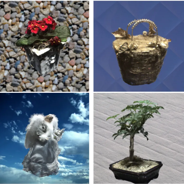
Figure 13:Surface light fields of several objects from new viewpoints. Note the alpha compositing with the textured backgrounds.