Petal: Distributed Virtual Disks
Edward K. Lee and Chandramohan A. Thekkath
Systems Research Center
Digital Equipment Corporation
130 Lytton Ave, Palo Alto, CA 94301.
Abstract
The ideal storage system is globally accessible, always available, provides unlimited performance and capacity for a large number of clients, and requires no management. This paper describes the design, implementation, and performance of Petal, a system that attempts to approximate this ideal in practice through a novel combination of features. Petal consists of a collection of network-connected servers that cooperatively manage a pool of physical disks. To a Petal client, this collection appears as a highly available block-level storage system that provides large abstract containers called virtual disks. A virtual disk is globally accessible to all Petal clients on the network. A client can create a virtual disk on demand to tap the entire capacity and performance of the underlying phys-ical resources. Furthermore, additional resources, such as servers and disks, can be automatically incorporated into Petal.
We have an initial Petal prototype consisting of four 225 MHz DEC 3000/700 workstations running Digital Unix and connected by a 155 Mbit/s ATM network. The prototype provides clients with virtual disks that tolerate and recover from disk, server, and network failures. Latency is comparable to a locally attached disk, and throughput scales with the number of servers. The prototype can achieve I/O rates of up to 3150 requests/sec and bandwidth up to 43.1 Mbytes/sec.
1
Introduction
Currently, managing large storage systems is an expensive and complicated process. Often a single component failure can halt the entire system, and requires considerable time and effort to resume operation. Moreover, the capacity and performance of individual components in the system must be periodically monitored and balanced to reduce fragmentation and eliminate hot spots. This usually requires manually moving, partitioning, or replicating files and directories.
This paper describes the design, implementation, and perfor-mance of Petal, an easy-to-manage distributed storage system. Clients, such as file systems and databases, view Petal as a collec-tion of virtual disks as shown in Figure 1. A Petal virtual disk is a
Published in The Proceedings of the 7th International Conference on Architectural Support for Programming Languages and Operating Systems. Copyright c 1996 by the Assocation for Computing Machinery. All rights reserved. Republished by permission. Scalable Network NT FS PC FS BSD FFS Petal /dev/vdisk11 /dev/vdisk2 /dev/vdisk3 /dev/vdisk4 /dev/vdisk5 (Petal Client) (Petal Client) (Petal Client) (Petal Client) LFS A virtual disk
Figure 1: Client View
container that provides a sparse 64-bit byte storage space. As with ordinary magnetic disks, data are read and written to Petal virtual disks in blocks. In addition, it has the following novel combination of characteristics, which we believe will reduce the complexity of managing large storage systems:
It can tolerate and recover from any single component failure such as disk, server, or network.
It can be geographically distributed to tolerate site failures such as power outages and natural disasters.
It transparently reconfigures to expand in performance and capacity as new servers and disks are added.
It uniformly balances load and capacity throughout the servers in the system.
It provides fast, efficient support for backup and recovery in environments with multiple types of clients, such as file servers and databases.
Petal’s virtual disks allow us to cleanly separate a client’s view of storage from the physical resources that are used to implement it. This allows us to share the physical resources more flexibly among many clients, and to offer important services such as “snapshots” and incremental expandability in an efficient manner.
The disk-like interface offered by Petal provides a lower-level service than a distributed file system; however, we believe that a distributed file system can be efficiently implemented on top of Petal, and that the resulting system as a whole will be as cost
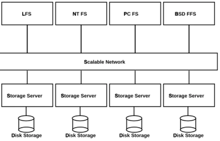
Scalable Network NT FS PC FS BSD FFS LFS Storage Server Storage Server Storage Server Storage Server Disk Storage Disk Storage Disk Storage Disk Storage
Figure 2: Physical View
effective as a comparable distributed file system implementation that accesses local disks directly. By separating the system cleanly into a block-level storage system and a file system, and by handling many of the distributed systems problems in the block-level storage system, we have an overall system that is easier to model, design, implement, and tune. This simplicity is particularly important when the design is expected to scale to a large size and provide reliable data storage over a long period of time. An additional benefit is that the block-level interface is useful for supporting heterogeneous clients and client applications; that is, we can easily support many different types of file systems and databases.
We have implemented Petal servers on Alpha workstations run-ning Digital Unix connected by the Digital ATM network [2]. A Petal client interface exists for Digital Unix and is implemented as a kernel device driver, allowing all standard Unix applications, utilities, and file systems to run unmodified when using Petal. Our implementation exhibits graceful scaling and provides perfor-mance that is comparable to local disks while providing significant new functionality.
2
Design of Petal
As shown in Figure 2, Petal consists of a pool of distributed storage servers that cooperatively implement a single, block-level storage system. Clients view the storage system as a collection of vir-tual disks and access Petal services via a remote procedure call (RPC) [3] interface. A basic principle in the design of the Petal RPC interface was to maintain all state needed for ensuring the in-tegrity of the storage system in the servers, and maintain only hints in the clients. Clients maintain only a small amount of high-level mapping information that is used to route read and write requests to the “most appropriate” server. If a request is sent to an inappro-priate server, the server returns an error code, causing the client to update its hints and retry the request.
Figure 3 illustrates the software structure of Petal. Each of the ovals represents a software module. Arrows indicate the use of one module by another. Two modules, the liveness module and the global state module, manage much of the distributed system aspect of Petal. The liveness module ensures that all servers in the system will agree on the operational status, whether running or crashed, of each other. This service is used by the other modules, notably the global state manager, to guarantee continuous, consistent operation of the system as a whole in the face of server and communication failures. The operation of the liveness module is based on majority
Recovery Module Liveness Module Global State Module Data Access Module Virtual to Physical Translator
Figure 3: Petal Server Modules
consensus and the periodic exchange of “I’m alive” and “You’re alive” messages between the servers. These message exchanges must be done in a timely manner to ensure progress but can be arbitrarily delayed or reordered without affecting correctness.
Petal maintains information that describes the current members of the storage system and the currently supported virtual disks. This information is replicated across all Petal servers in the system. The global state manager is responsible for consistently maintain-ing this information, which is less than a megabyte in our current implementation. Our algorithm for maintaining global state is based on Leslie Lamport’s Paxos, or “part-time parliament” algo-rithm [14] for implementing distributed, replicated state machines. The algorithm assumes that servers fail by ceasing to operate and that networks can reorder and lose messages. The algorithm en-sures correctness in the face of arbitrary combinations of server and communication failures and recoveries, and guarantees progress as long as a majority of servers can communicate with each other. This ensures that management operations in Petal, such as creat-ing, deletcreat-ing, or snapshotting virtual disks, or adding and deleting servers, are fault tolerant.
The other three modules deal with servicing the read and write requests issued by Petal clients. The data access and recovery mod-ules control how client data is distributed and stored in the Petal storage system. A different set of data access and recovery mod-ules exists for each type of redundancy scheme supported by the system. We currently support simple data striping without redun-dancy and a replication-based redunredun-dancy scheme called
chained-declustering [13]. The desired redundancy scheme for a virtual
disk is specified when the virtual disk is created. Subsequently, the redundancy scheme, and other attributes, can be transparently changed via a process called virtual disk reconfiguration. The virtual-to-physical address translation module contains common routines used by the various data access and recovery modules. These routines translate the virtual disk offsets to physical disk addresses. The rest of this section will examine specific aspects of the system in greater detail.
2.1
Virtual to Physical Translation
This section describes how Petal translates the virtual disk ad-dresses used by clients into physical disk adad-dresses. The basic problem is to translate virtual addresses of the form virtual-disk-identifier, offset to physical addresses of the form server-identifier, disk-server-identifier, disk-offset . This translation must be done consistently and efficiently in a distributed system where events that alter virtual disk address translation, such as server
GMap Server 0 Server 1 Server 2 Server 3
offset serverID GMap
GMap PMap0 PMap1 PMap2 PMap3 VDir VDir VDir VDir vdiskID
<vdiskID, offset> −> <serverID, diskID, diskOffset>
<diskID, diskOffset>
Figure 4: Virtual to Physical Mapping
failure or recovery, can occur unexpectedly.
Figure 4 illustrates the basic data structures and the steps in the translation procedure. There are three important data structures: a virtual disk directory (VDir), a global map (GMap), and a physical map (PMap). The dotted lines around the virtual disk directory and the global map indicate that these are global data structures that are replicated and consistently updated on all the servers by the global state manager. Each server also has a physical map that is local to that server. Translating a client-supplied virtual disk identifier and offset into a particular disk offset occurs in three steps as shown in Figure 4.
1. The virtual disk directory translates the client-supplied virtual disk identifier into a global map identifier.
2. The specified global map determines the server responsible for translating the given offset.
3. The physical map at the specified server translates the global map identifier and the offset to a physical disk and an offset within that disk.
To minimize communication, in almost all cases, the server that performs the translation in Step 2 will be the same server that performs the translation in Step 3. Thus, if a client has initially sent the request to the appropriate server, that server can perform all three steps in the translation locally without communicating with any other server.
There is one global map per virtual disk that specifies the tuple of servers spanned by the virtual disk and the redundancy scheme used to protect client data stored on the virtual disk. To tolerate server failures, a secondary server can be assigned responsibility for mapping the same offset when the primary is not available. Global maps are immutable; to change a virtual disk’s tuple of servers or redundancy scheme, the virtual disk must be assigned a new global map. Section 2.3 describing reconfiguration provides more details about this process.
The physical map is the actual data structure used to translate an offset within a virtual disk to a physical disk and an offset within that disk. It is similar to a page table in a virtual memory system and each physical map entry translates a 64 Kbyte region of physical disk. The server that performs the translation will usually also perform the disk operations needed to service the original client request. The separation of the translation data structures into global and local physical maps allows us to keep the bulk of
the mapping information local. Doing so minimizes the amount of information that must be kept in global data structures that are replicated and, therefore, expensive to update.
2.2
Support for Backup
Petal attempts to simplify a client’s backup procedure by providing a common mechanism that can be applied by clients to automate the backup and recovery of all data stored on the system. The mechanism Petal provides is fast efficient snapshots of virtual disks. By using copy-on-write techniques, Petal can quickly create an exact copy of a virtual disk at a specified point in time. A client treats the snapshot like any other virtual disk, except that it cannot be modified.
Supporting snapshots requires a slightly more complicated virtual-to-physical translation procedure than described in the pre-vious section. In particular, the virtual disk directory does not translate a virtual disk identifier to a global map identifier, but rather to the tuple global-map-identifier, epoch-number . The epoch-number is a monotonically increasing version number that distinguishes data stored at the same virtual disk offset at different points in time. The tuple global-map-identifier, epoch-number is then used by the physical map in the last step of the translation.
When the system creates a snapshot of a virtual disk, a new tuple with a later epoch number is created in the virtual disk directory. All accesses to the original virtual disk are then made using the new epoch number. The older epoch number is used by the newly created snapshot. This ensures that any new data written to the original virtual disk will create new entries in the new epoch rather than overwriting the data in the previous epoch. Also, read requests can find the data most recently written to a particular offset by looking for the most recent epoch.
Creating a snapshot that is consistent at the client application level requires pausing the application for the brief time, less than one second, it takes to create a Petal snapshot. An alternative approach would not require pausing the application and would create a “crash-consistent” snapshot, that is, the snapshot would be similar to the disk image that would be left after an application crashed. Such snapshots could later be made consistent at the application level by running an application-dependent recovery program such asfsckin the case of Unix file systems. We are considering implementing crash-consistent snapshots, but they are currently not supported.
Snapshots can be kept on-line and facilitate the recovery of ac-cidentally deleted files. Also, since a snapshot behaves exactly like a read-only local disk, a Petal client can use it to create consistent archives of data using utilities such astar.
2.3
Incremental Reconfiguration
Occasionally, it is desirable to change a virtual disk’s redundancy scheme or the set of servers over which it is mapped. Such a change is often precipitated by the addition or removal of disks and servers. This section describes how Petal incorporates new disks and servers, and how existing virtual disks can be reconfigured to take advantage of these new resources. The former processes are described only from the point of view of adding new resources but are easily generalized to the removal of resources. The latter process is referred to as virtual disk reconfiguration and is the primary focus of this section.
The addition of a disk to a server is handled locally by the given server. Subsequent storage allocation requests automatically take
the new disk into consideration. However, for load balance, it is desirable to redistribute previously allocated storage to the new disk as well. This redistribution is most easily accomplished as part of a local background process that periodically moves data among disks. We have not yet implemented such a background process in Petal. Nonetheless, existing data is redistributed to newly added disks as a side-effect of the virtual disk reconfiguration.
The addition of a Petal server is a global operation composed of several steps involving the global state management module and the liveness module. First, the new server is added to the membership of the Petal storage system. Thereafter, the new server will participate in any future global operations. Next, the sets of servers used by the liveness module for determining whether a particular server is up or down is adjusted to incorporate the new server. Finally, existing virtual disks are reconfigured to take advantage of the new server, using the process described below.
Given the virtual-to-physical translation procedure already de-scribed in Section 2.1, and in the absence of any other activity in the system, virtual disk reconfiguration can be trivially implemented as follows:
1. Create a new global map with the desired redundancy scheme and server mapping.
2. Change all virtual disk directory entries that refer to the old global map to refer to the new one.
3. Redistribute the data to the servers according to the transla-tions specified in the new global map. This data distribution could potentially require substantial amounts of network and disk traffic.
The challenge is to perform reconfiguration incrementally and con-currently with the processing of normal client requests. We find it acceptable if the procedure takes a few hours but it must not de-grade the performance of the system significantly. For example, if a virtual disk is reconfigured because a new server has been added, the performance of the virtual disk should gradually increase dur-ing reconfiguration from its level before reconfiguration to its level after reconfiguration. We will describe our reconfiguration algo-rithm in two steps. First, we describe the basic algoalgo-rithm and then a refinement to that algorithm. The refined algorithm is what is actually implemented in our system.
In the basic algorithm, steps one and two, described above, are first executed. Next, starting with the translations in the most recent epoch that have not yet been moved, data is transferred to the new collection of servers as specified by the new global map. Because of the amount of data that may need to be moved, reconfiguration can take a long time to complete. In the meantime, clients will wish to read and write data to a virtual disk that is being reconfigured. To accommodate such requests, our read and write procedures are designed to function as follows. When a client read request is serviced, the old global map is tried if an appropriate translation is not found in the new global map. This ensures that translations that have not yet been moved will still be found in the old global map. Any client write requests will always access only the new global map. Also, since we move data starting with the most recent epoch, we ensure that read requests will not return data from an older epoch than that requested by the client.
The main limitation of the basic algorithm is that server map-pings for an entire virtual disk are changed before any data is moved. This means that almost every client read request submitted that is based on the new global map will miss in the new global
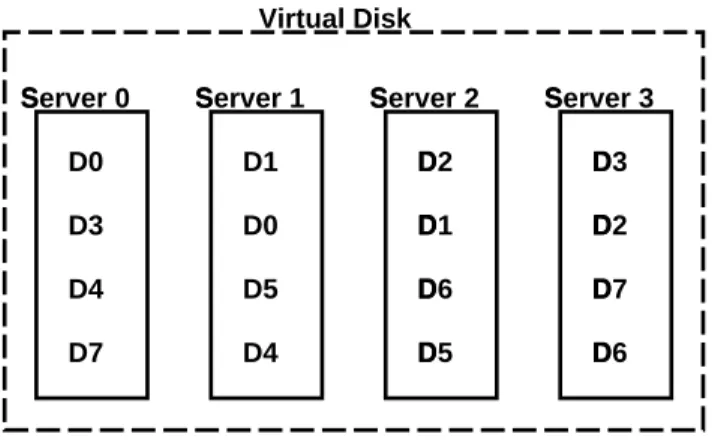
Server 1 Server 2 Server 3 Server 0 D0 D0 D1 D1 D2 D2 D3 D3 D4 D4 D5 D5 D6 D6 D7 D7 Virtual Disk Figure 5: Chained-Declustering
map and will have to be forwarded to the old one. This will usu-ally require additional communication between servers and has the potential to seriously degrade the performance of the system.
The refined algorithm solves the limitation of the basic algorithm by relocating only small portions of a virtual disk at a time. The basic idea is to break up a virtual disk’s address range into three regions: old, new, and fenced. Requests to the old and new regions simply use the old and new global maps, respectively. Requests to the fenced region, however, use the basic algorithm we have described above. Once we have relocated everything in the fenced region, it becomes a new region and we fence another part of the old region. We repeat until we have moved all the data in the old region into the new region.
By keeping the relative size of the fenced region small, roughly one to ten percent of the entire range, we minimize the forward-ing overhead. To help guard against fencforward-ing off a heavily used subrange of the virtual disk, we construct the fenced region by collecting small non-contiguous ranges distributed throughout the virtual disk, instead of a single contiguous region.
2.4
Data Access and Recovery
This section describes Petal’s chained-declustered [13] data access and recovery modules. These modules give clients highly available access to data by automatically bypassing failed components. Dy-namic load balancing eliminates system bottlenecks by ensuring uniform load distribution even in the face of component failures. We start by describing the basic idea behind chained-declustering and then move into detailed descriptions of exactly what happens on each read and write operation.
Figure 5 illustrates the chained-declustered data placement scheme. The dotted rectangle emphasizes that the data on the storage servers appear as a single virtual disk to clients. Each sequence of letters represents a block of data stored in the stor-age system. Note that the two copies of each block of data are always stored on neighboring servers.Furthermore, every pair of neighboring servers has data blocks in common. Because of this arrangement, if Server 1 fails, servers 0 and 2 will automatically share Server 1’s read load; however, Server 3 will not experience any load increase. By performing dynamic load balancing, we can do better. For example, since Server 3 has copies of some data from servers 0 and 2, servers 0 and 2 can offload some of their normal read load on Server 3 and achieve uniform load balancing. Chaining the data placement allows each server to offload some of its read load to the server either immediately following or
pre-ceding the given server. By cascading the offloading across multi-ple serv
ers, a uniform load can be maintained across all surviving servers. In contrast, with a simple mirrored redundancy scheme that replicates all the data stored on two servers, the failure of either would result in a 100% load increase at the other with no opportunities for dynamic load balancing. In a system that stripes over many mirrored servers, the 100% load increase at this single server would reduce the overall system throughput by 50%.
Our current prototype implements a simple dynamic load bal-ancing scheme. Each client keeps track of the number of requests it has pending at each server and always sends read requests to the server with the shorter queue length. This works well if most of the requests are generated by a few clients but, obviously, would not work well if most requests are generated by many clients that only occasionally issue I/O requests. The choice of load balancing algorithm is currently an active area of research within the Petal project.
An additional advantage with chained-declustering is that by placing all the even-numbered servers at one site and all the odd-numbered servers at another site, we can tolerate site failures. A disadvantage of chained-declustering relative to simple mirroring is that it is less reliable. With simple mirroring, if a server failed, only the failure of its mirror server would result in data becoming unavailable. With chained-declustering, if a server fails, the failure of either one of its two neighboring servers will result in data become unavailable.
In our implementation of chained-declustering, one of the two copies of each data block is denoted the primary and the other is denoted the secondary. Read requests can be serviced from either the primary or the secondary copy but the servicing of write re-quests must always start at the primary, unless the server containing the primary is down in which case it may start at the secondary. Because we lock copies of the data blocks before reading or writing them to guarantee consistency, this ordering guarantee is necessary to avoid deadlocks.
On a read request, the server that receives the request attempts to read the requested data. If successful, the server returns the requested data, otherwise it returns an error code and the client tries another server. If a request times out due to network congestion or because a server is down, the client will alternately retry the primary and secondary servers until either the request succeeds or both servers return error codes indicating that it is not possible to satisfy the request. Currently, this happens only if both disks containing copies of the requested data have been destroyed.
On a write request, the server that receives the request first checks to see if it is the primary for the specified data element. If it is the primary, it first marks this data element as busy on stable storage. It then simultaneously sends write requests to its local copy and the secondary copy. When both requests complete, the busy bit is cleared and the client that issued the request is sent a status code indicating the success or failure of the operation. If the primary crashes while performing the update, the busy bits are used during crash recovery to ensure that the primary and secondary copies are consistent. Write-ahead-logging with group commits makes updating the busy bits efficient. As a further optimization, the clearing of busy bits is done lazily and we maintain a cache of the most recently set busy bits. Thus, if write requests display locality, a given busy bit will already be set on disk and will not require additional I/O.
If the server that received the write request is the secondary for the specified data element, then it will service the request only if it can determine that the server containing the primary copy is
Petal Client Petal Client Petal Client Petal Client
Petal Virtual Disk
Log Petal Server Log Petal Server Log Petal Server Log Petal Server
Digital ATM Network
Figure 6: Petal Prototype
down. In this case, the secondary marks the data element as stale on stable storage before writing it to its local disk. The server containing the primary copy will eventually have to bring all data elements marked stale up-to-date during its recovery process. A similar procedure is used by the primary if the secondary dies.
3
Implementation and Performance
Our Petal prototype is illustrated in Figure 6. Four 225 MHz DEC 3000/700s running Digital Unix act as server machines. Each runs a single Petal server, which is a user-level process that accesses the physical disks using the Unix raw disk interface, and the network using UDP/IP Unix sockets. Each server machine is configured with 14 Digital RZ29 disks, each of which is a 3.5 inch SCSI device with a 4.3 Gbyte capacity. Each machine uses one of the disks for write-ahead logging and the remaining to store client data. The disks are connected to the server machine via two 10 Mbyte/s fast SCSI strings using the Digital PMZAA-C host bus adapter.
Four additional machines running Digital Unix are configured as Petal clients to generate load on the servers. Each client’s kernel is loaded with the Petal device driver for accessing Petal virtual disks. This allows clients to access Petal virtual disks just like local disks. Both the servers and clients are connected to each other via 155 Mbit/s ATM links over a Digital ATM network.
The entire Petal RPC interface has 24 calls and many of these calls are devoted to management functions, such as creating and deleting virtual disks, making snapshots, reconfiguring a virtual disk, and adding and deleting servers. These calls are typically used by user-level utilities to perform tasks such as virtual disk creation and monitoring the physical resource pools in the system to determine when additional servers or disk should be added.
Petal RPC calls that implement management functions are infre-quently executed and generally take less than a second to complete. In particular, create and snapshot operations take about 650 mil-liseconds. Delete and reconfiguration take about 650 milliseconds to initiate, but their total execution time is dependent on the actual amount of physical storage associated with the specified virtual disk.
In the remainder of the section, we will report on the perfor-mance of accessing a Petal virtual disk and the behavior of file sys-tems built on Petal. Our primary performance goals are to provide latency roughly comparable to a locally attached disk,
through-Client Request Latency (ms)
Request Local Disk Petal
RZ29 Log NVRAM Log
512 byte Read 9 10 10 8 Kbyte Read 11 12 12 64 Kbyte Read 21 28 28 512 byte Write 10 19 12 8 Kbyte Write 12 22 16 64 Kbyte Write 20 40 33
Table 1: Latency of a Chained-Declustered Virtual Disk
put that scales with the number of servers, and performance that gracefully degrades as servers fail.
3.1
Petal Performance
This section examines the read and write performance of a Petal chain-declustered virtual disk. For a read request, the client makes an RPC to a Petal server that simply returns the data from its local disk. When a server receives a write request, it first writes a small log entry that is used to recover to a consistent state after a server crash. Next, the server simultaneously writes the data to its local disk and a second disk on a mirror server. When both disk writes complete, the first, or primary, server replies to the client. The read and write procedures used by Petal are described in greater detail in Section 2.4.
Table 1 compares the read and write latency of a chained-declustered Petal virtual disk with a local RZ29 disk. For this experiment, a single client generates requests of the specified size to random disk offsets. We show Petal performance with two kinds of write-ahead-logging devices, an RZ29 disk and an NVRAM de-vice simulated using RAM. The log dede-vice is used only to serde-vice write requests and does not affect read performance. Logging to NVRAM improves write latency by approximately 7 ms.
For read requests of 512 bytes and 8 Kbytes, the Petal latency is only slightly worse than an RZ29. For 64 Kbyte reads, the latency gap widens to 7 ms. Most of the increased latency is due to the additional delay in transmitting the data over the network and includes the Unix socket, UDP/IP, and ATM hardware overheads, which accounts for over 6 ms. The Petal server software and the client interface overheads are negligible. If we overlapped the reading of data from disks with the transfer of data over the network, we could eliminate much of this 7 ms overhead.
Even with an NVRAM log device, Petal write performance is worse than a local RZ29 disk. In addition to the network delay in sending the data to the primary server, there is an additional delay because the primary has to send the data to the mirror server and wait for an acknowledgment before returning to the client. The latencies due to the network transmissions are approximately 1 ms, 3 ms, and 12 ms for 512 byte, 8 Kbyte, and 64 Kbyte write requests respectively. Also, the arms and the spindles of the primary and secondary disks are unsynchronized. This lack of synchronization causes write requests to wait for the slower of the primary and secondary disk writes.
The second column of Table 2 shows the peak throughput of a chained-declustered Petal virtual disk using an RZ29 as a log device. (The peak write throughput is about 10% higher if we use an NVRAM log device.) For small request sizes, we express throughput as the number of requests per second, while for larger request sizes, it is shown in megabytes per second. To measure
Aggregate Throughput (RZ29 Log)
Request Normal Failed % of Normal
512 byte Read 3150 req/s 2310 req/s 73 % 8 Kbyte Read 20 Mbytes/s 14.6 Mbytes/s 73 % 64 Kbyte Read 43.1 Mbytes/s 33.7 Mbytes/s 78 % 512 byte Write 1030 req/s 1055 req/s 102 % 8 Kbyte Write 6.6 Mbytes/s 6.6 Mbytes/s 100 % 64 Kbyte Write 12.3 Mbytes/s 12.5 Mbytes/s 101 %
Table 2: Normal and Failed Throughput of a Chained-Declustered Virtual Disk 512 byte Read 8 Kbyte Read 64 Kbyte Read 512 byte Write 8 Kbyte Write 64 Kbyte Write
|
0 !|
1 "|
2 #|
3$|
4 %|
5 &|
' 0.00|
' 0.20|
' 0.40|
' 0.60|
' 0.80|
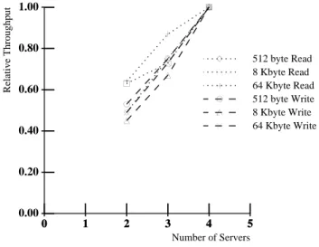
' 1.00 Number of Servers Relative Throughput ( ( ( ) ) ) * * * + + + , , ,-Figure 7: Scaling with Increased Servers
peak throughput, each of the four Petal clients shown in Figure 6 make random requests to a single Petal virtual disk.
Throughput is mostly limited by CPU overheads. In all cases, each server’s CPU is approximately 90-100% utilized with a sig-nificant fraction of the time spent in copying and checksumming data for network access. Our Petal servers run at user-level and we use the standard UNIX socket interface and UDP/IP protocol stacks. Techniques for streamlining these network accesses are well understood [9, 18]. As an experiment, we eliminated copy-ing and checksums at the network layer for large read requests. For 64 Kbyte read requests, this optimization reduced CPU uti-lization to 48% and increased throughput from 43.1 Mbytes/s to 48.5 Mbytes/s. In this case, the throughput was limited by the disk controller.
The third column of Table 2 shows the performance of a chain-declustered Petal disk when one of the four servers has crashed. For read requests, the performance is 73–78% of normal, that is, with three-quarters of the servers, we get about three-quarters of the normal performance. This indicates that the data placement and dynamic load balancing schemes are working effectively to redistribute load. The write performance under failure is about the same as the normal case. This is because, when servers fail, the virtual disk addresses managed by those servers are no longer mirrored. This reduces the number of disk writes in the system by the fraction of failed servers. Therefore, the load seen by each surviving server before and after a server failure is nearly the same. Figure 7 shows the effect of scaling Petal from two to four servers. The throughput for each request type is normalized with respect to the maximum throughput for that request type. The
Elapsed Time (seconds)
UFS AdvFS
Phase RZ29 Petal RZ29 Petal
Create Directories 0.9 1.4 0.28 0.28 Copy Files 4.1 4.4 3.6 3.7 Directory Status 4.3 4.1 4.2 4.6 Scan Files 5.1 5.2 5.2 5.3 Compile 41.1 41.8 40.0 40.6
Table 3: Modified Andrew Benchmark
system configurations measured are not large enough to determine if the scaling is likely to remain linear, but the observed scaling is promising.
3.2
File System Performance
Petal provides clients with a large virtual disk that is available to all clients on the network. “Cluster file systems” such as the xFS [1] and parallel databases such as the Oracle Parallel Server may be able to take advantage of this fact by concurrently accessing a single virtual disk from multiple machines. However, because such systems are not widely available, we will restrict our attention to Digital’s UNIX File System (UFS) and Advanced File System (AdvFS).
Table 3 compares the performance of the Modified Andrew Benchmark on four configurations: the UFS on a locally attached disk, the UFS on a Petal virtual disk, the AdvFS on a collection of 14 locally attached disks, and the AdvFS on a Petal virtual disk. The Petal virtual disk is configured to use the chain-declustered data placement and an RZ29 disk for logging.
The Modified Andrew Benchmark has five phases. The first phase recursively creates subdirectories. The second phase mea-sures the file system’s data transfer capabilities. The third phase recursively examines the status of directories and the files contained therein. The fourth phase scans the contents of data stored in each file. The final phase is indicative of the program development phase and is somewhat computationally intensive.
In all cases but one, the file system level performance of the Petal virtual disk is comparable to locally attached disks. The only ex-ception is in the first phase of the benchmark using the UFS, which generates many synchronous writes. As we mentioned earlier, writes to a chained-declustered Petal virtual disk can incur logging and other overheads that increase the synchronous write latency. The AdvFS, which journals meta-data updates to reduce the num-ber of synchronous writes, does not suffer from these overheads when running on Petal, and achieves much higher performance than the UFS in the first phase of the benchmark.
In the local disk measurements, although the UFS uses only a single disk while the AdvFS uses 14 disks,they achieve very similar performance. This is because the Modified Andrew Benchmark primarily stresses the latency rather than the throughput of the storage system. In the case of the compilation phase, performance is primarily limited by the speed of the CPU.
4
Discussion
The availability of cost-effective scalable networks is the driving force behind our work. By thinking of the network as the primary system-level interconnect, we can build incrementally expandable distributed storage systems with availability, capacity, and perfor-mance far beyond those of current centralized storage systems.
Unfortunately, such distributed storage systems, pose several diffi-cult management and consistency problems. Petal is an experiment in trying to address these problems.
Petal uses virtual disks to hide the distributed nature of the sys-tem from its clients. It allows independent applications to share the performance and capacity of the physical storage resources in the system. It can transparently incorporate new storage components and provide convenient management features such as snapshots. We currently do not provide any special support for protecting a client’s data from other clients; however, it would not be difficult to provide security on a per virtual disk basis.
Petal’s use of the virtual disk abstraction adds an additional level of overhead, and can prevent application-specific disk op-timizations that rely on careful placement of data. We believe that this is not a serious problem and is a reasonable tradeoff for the benefits that Petal can provide. We view the virtualization as another example of the current trend towards sophisticated disk array controllers, and SCSI disks that obscure the physical disk geometry. In fact, each Petal server is of approximately the same complexity as a RAID controller and has very similar hardware resource requirements.
Petal provides a disk-like interface that allows clients to read and write blocks of data. We chose this interface because it can be easily integrated into any existing computer system and can transparently support most existing file systems and databases. One alternative to Petal is to design distributed storage with a richer interface that is more like a file system as is being done in the CMU NASD project [11]. This could potentially result in a system that is more efficient overall; however, we currently believe that the simpler Petal interface is adequate and that higher level services can be efficiently built on top of it.
Petal’s framework is sufficiently general to incorporate other classes of redundancy schemes such as those based on parity [5, 17]. However, we have chosen to concentrate on replication-based re-dundancy schemes like chained-declustering, even though they impose a higher capacity overhead, because they are more read-ily applicable for tolerating site failures, present opportunities for dynamic load balancing, and are easier to implement efficiently in distributed systems.
5
Related Work
This section describes work related to Petal in terms of four primary characteristics: type of abstraction (block-level or file-system-level), degree of distribution, level of fault tolerance, and support for incremental expandability.
Related block-level storage systems include RAID-II [7], TickerTAIP [5], Logical Disk [8], Loge [10], Mime [6], Au-toRAID [19], and Swift [4]. Some of these systems support only simple algorithmic mappings between the address space seen by a client and the underlying physical disks. This mapping is usually completely specified when the system is configured. In contrast, AutoRAID, Logical Disk, Loge, and Mime, like Petal, support more flexible mappings by using index data structures. Except for AutoRAID and Petal, none of these systems support the creation of multiple virtual disks.
Most of the block-level systems, including AutoRAID, do not support distribution across multiple nodes or over geographically distributed sites. Two exceptions are TickerTAIP and Swift, both of which provide support for distributing data over multiple nodes. However, both assume that the communication interconnect is
re-liable and therefore do not deal with the full range of distributed systems issues addressed by Petal. Although many of the systems above can tolerate disk failures, TickerTAIP is the only one that can tolerate node failures. In contrast, Petal supports wider distribution and can tolerate both node and network failures.
The most closely related file systems include xFS [1], Zebra [12], Echo [15], and AFS [16]. All these systems except xFS use a single meta-data server for a given partial subtree of the file system name space; ultimately limiting their scalability. Because xFS can distribute the management of meta-data across multiple nodes on an object-by-object basis, it is one of the few file systems that we know of that does not suffer from this problem.
All the file and disk systems above can be considered incre-mentally expandable in the sense that data can be first dumped to tape and then later restored after adding extra components and reconfiguring the system. Some of these systems go a step further. Both Zebra and AutoRAID allow new disks to be incorporated into the system dynamically and transparently with respect to its clients. AFS allows new nodes to be added and volumes, corre-sponding to partial subtrees of the file system name space, to be moved between nodes transparently; however, AFS does not allow a volume to span more than a single node. This is in contrast with Petal where a virtual disk can span multiple nodes. A goal of the xFS design is to be able to change the management node for a particular file dynamically for load balancing or in response to node additions or deletions. However, this functionality has not yet been implemented.
Petal supports the addition and deletion of nodes from the system in the face of arbitrary node and network failures, and a Petal virtual disk, which can span multiple nodes, can be transparently reconfig-ured to take advantage of the additional nodes. This reconfiguration is transparent to Petal clients. To the best of our knowledge, Petal is the first distributed block-level storage system that supports vir-tual “containers.” Because managing physical resources becomes more difficult as the storage system becomes larger and more dis-tributed, we have found that distribution and virtual containers are particularly powerful when combined. Distribution allows the sys-tem to scale to large sizes and virtual containers make it easier to allocate physical resources efficiently in large-scale systems. Petal is also the first storage system that supports transparent ad-dition and deletion of nodes to existing “storage containers” in the face of arbitrary component and network failures. This allows the system-level performance of a single container to scale gracefully as additional nodes are added.
6
Summary and Conclusions
Petal is a distributed block-level storage system that tolerates and recovers from any single component failure, dynamically balances load between servers, and transparently expands in performance and capacity. Our principal goal has been to design a storage sys-tem for heterogeneous environments that is easy to manage and that can scale gracefully in capacity and performance without sig-nificantly increasing the cost of managing the system. We believe that we have found a novel combination of features that allow us to achieve this goal; however, only the actual use of the system over a significant period of time can conclusively prove this assertion.
In designing Petal, we decided to use distributed software so-lutions rather than hardware soso-lutions whenever applicable. One example of this software/hardware tradeoff is Petal’s strategy for fault tolerance, which uses distributed mirroring rather than
provid-ing redundant hardware paths to each disk. This approach makes it easier to geographically distribute the system and to scale to larger system sizes. Another tradeoff is the use of distributed algorithms to determine when servers have failed, or more generally to achieve consensus, rather than using reliable communication hardware or specialized hardware for synchronization.
Petal provides a block-level rather than a file-level interface. This allows Petal to handle heterogeneous client file systems grace-fully. The choice of a block-level interface has greatly simplified our work without adversely limiting the functionality that we can provide. It also opens the possibility of encapsulating the Petal server software into a disk array controller in much the same way RAID software is encapsulated into disk array controllers today.
Petal’s virtual disks have proved invaluable in separating a client’s view of storage from the physical resources in the sys-tem. Virtualization makes it easier to allocate physical resources among many heterogeneous clients and has enabled useful features such as snapshots and transparent incremental expandability.
We are generally satisfied with the performance of our proto-type. The read and write latencies for a chain-declustered Petal virtual disk are somewhat larger than that for a locally attached disk. We can achieve I/O rates up to 3150 requests/sec for small read requests and bandwidth up to 43.1 Mbytes/sec for large read requests. The throughput for write request is less but we believe that we understand how to improve their significantly performance. The performance of Petal degrades gracefully as a fraction of the number of failed servers and the throughput of the system scales well with the number of servers. We have not measured a suffi-ciently large system to determine whether the performance scaling is linear, but we feel confident that it will be. The prototype has been running for the past several months and we are currently working on building a larger production system for deployment and day-to-day use at our laboratory.
Acknowledgments
The authors would like to thank Roger Needham, Mike Schroeder, Bill Weihl, and the anonymous referees for their comments on earlier drafts of the paper. Cynthia Hibbard provided valuable editorial assistance.
References
[1] Thomas E. Anderson, Michael D. Dahlin, Jeanna M. Neefe, David A. Patterson, Drew S. Roselli, and Randolph Y. Wang. Serverless network file systems. ACM Transactions on
Com-puter Systems, 14(1):41–79, February 1996.
[2] Thomas E. Anderson, Susan S. Owicki, James B. Saxe, and Charles P. Thacker. High-speed switch scheduling for local-area networks. ACM Transactions on Computer Systems, 11(4):319–352, November 1993.
[3] Andrew D. Birrell and Bruce Jay Nelson. Implementing remote procedure calls. ACM Transactions on Computer
Systems, 2(1):39–59, February 1984.
[4] Luis-Felipe Cabrera and Darrel D. E. Long. Swift: Using distributed disk striping to provide high I/O data rates. ACM
Computing Systems, 4:405–436, Fall 1991.
[5] Pei Cao, Swee Boon Lim, Shivakumar Venkataraman, and John Wilkes. The TickerTAIP parallel RAID architecture.
ACM Transactions on Computer Systems, 12(3):236–269,
August 1994.
[6] C. Chao, R. English, D. Jacobson, A. Stepanov, and J. Wilkes. Mime: A high performance parallel storage device with strong recovery guarantees. Technical Report HPL-CSP-92-9, Hewlett-Packard Laboratories, November 1992.
[7] Peter M. Chen, Edward K. Lee, Ann L. Drapeau, Ken Lutz, Ethan L. Miller, Srinivasan Seshan, Ken Shirriff, David A. Patterson, and Randy H. Katz. Performance and design eval-uation of the RAID-II storage server. Journal of Distributed
and Parallel Databases, 2(3):243–260, July 1994.
[8] Wiebren de Jonge, M. Frans Kaashoek, and Wilson C. Hsieh. The logical disk: A new approach to improving file systems. In Proceedings of the 14th ACM Symposium on Operating
Systems Principles, pages 15–28, December 1989.
[9] Peter Druschel, Larry L. Peterson, and Bruce S. Davie. Ex-periences with a high-speed network adaptor: A software perspective. In Proceedings of the 1994 SIGCOMM
Sympo-sium on Communications Architectures, Protocols and Ap-plications, pages 2–13, August 1994.
[10] R. M. English and A. A. Stepanov. Loge: A self-organizing disk controller. In Proceedings of the Winter 1992 USENIX
Conference, pages 237–251, January 1992.
[11] Garth A. Gibson, David F. Nagle, Khalil Amiri, Fay W. Chang, Eugene Feinberg, Howard Gobioff, Chen Lee, Berend
Ozceri, Erik Riedel, and David Rochberg. A case for
network-attached secure disks. Technical Report CMU-CS-96-142, Department of Electrical and Computer Engineering, Carnegie-Mellon University, June 1996.
[12] John H. Hartman and John K. Ousterhout. The Zebra striped network file system. ACM Transactions on Computer
Sys-tems, 13(3):274–310, August 1995.
[13] Hui-I Hsiao and David J. DeWitt. Chained declustering: A new availability strategy for multiprocessor database ma-chines. Technical Report CS TR 854, University of Wiscon-sin, Madison, June 1989.
[14] Leslie Lamport. The Part-Time Parliament. Technical Re-port 49, Digital Equipment Corporation, Systems Research Center, 130 Lytton Ave., Palo Alto, CA 94301-1044, Septem-ber 1989.
[15] Timothy Mann, Andrew D. Birrell, Andy Hisgen, Chuck Jerian, and Garret Swart. A coherent distributed file cache with directory write-behind. ACM Transactions on Computer
Systems, 12(2):123–164, May 1994.
[16] M. Satyanarayanan. Scalable, secure, and highly available distributed file access. IEEE Computer, 23(5):9–21, May 1990.
[17] Daniel Stodolsky, Mark Holland, William V. Courtright II, and Garth A. Gibson. Parity-logging disk arrays. ACM
Trans-actions on Computer Systems, 12(3):206–235, August 1994.
[18] Chandramohan A. Thekkath and Henry M. Levy. Limits to low-latency communication on high-speed networks. ACM
Transactions on Computer Systems, 11(2):179–203, May
1993.
[19] John Wilkes, Richard Golding, Carl Staelin, and Tim Sul-livan. The HP AutoRAID hierarchical storage system. In
Proceedings of the 15th ACM Symposium on Operating Sys-tems Principles, pages 96–108, December 1995.