The Living Software Development Process
1Michael Gnatz, Frank Marschall, Gerhard Popp, Andreas Rausch, Wolfgang Schwerin
Institut für Informatik Technische Universität München
Boltzmannstraße 3 85748 Garching, Germany
(gnatzm|marschal|popp|rausch|schwerin)@in.tum.de
Abstract: Today’s software development projects are confronted with a frequently
changing environment like rapidly altering business domains and processes, a fast tech-nology evolution and a great variety of evolving methods and development processes. Therefore highly flexible and adaptable software development processes are required, which allow projects to react on changes quickly and to adopt existing development methods to comply with the projects’ actual needs. Such a process, which allows static and dynamic tailoring and evolutionary improvements, is called a living software devel-opment process. This article introduces a common process framework for the living software development process based on the concepts of process patterns and work arte-facts. The proposed framework enables software engineers to define, evolve and apply a flexible development process with respect to the daily needs of their software develop-ment project. A running example guides the reader through the article.
Keywords: Software Development Process, Process Modelling, Process Tailoring,
Process Improvement, Process Patterns
1
This work originates form the research project ZEN – Center for Technology, Methodology and Management of Software & Systems Development – a part of Bayerischer Forschungsverbund Software-Engineering (FORSOFT), supported by the Bayerische Forschungsstiftung.
1 Introduction
Software engineering focuses on producing high quality software products in a given time and money budget. Empirical studies and research results have shown that applying a well defined, organization-wide, standardized software development process has profound influence on the magic triangle of time, costs, and quality. The CHAOS Ten software project success factor number eight is “formal project management methodology”, which results in steps and proce-dures the project team can reproduce and reuse (Standish 2001). Following a standardized, repeatable development process increases software quality and makes the software develop-ment more predictable and economic (Cugola 1998).
However, industrial software producers work in a highly dynamic market: Organizational and structural aspects of projects and customers alter, customer requirements have an inevita-ble tendency to change, and new technologies have to be adopted. To produce competitively high quality products you have to manage the change. This implies that you must be able to quickly adapt your development processes with respect to upcoming changes (Weinberg 1997).
For example, assume a perfect customer providing a well elaborated requirements docu-ment for your project – developing an insurance policy managedocu-ment system. During analysis and design phase it turns out that the management of the insurance company had a clear under-standing of the system functionality, which was harmonized with the in-house accounting clerks but not with the independent insurance policy brokers selling and maintaining the insur-ance policies of the company’s customers. To develop a high quality and accepted system you have to involve these additional stakeholders into requirements analysis. In this case it might be advantageous to change the development process. All design and analyse activities are stopped. A new requirements elicitation phase involving all system’s stakeholder based on a rapid prototyping approach is started.
As one can see, a software development process must not constrain a project leader and his software engineers to follow a predefined sequence of activities, contrariwise it should pro-vide support and space for their creative tasks. Therefore it must be highly flexible and, in addi-tion, adaptable with respect to the frequent changes of system’s requirements and the environment in which it is applied.
Existing process models, like the V-Model (Dröschel 1999) or the Rational Unified Proc-ess (Kruchten 2000), contain the concept of static tailoring to allow more flexibility. This con-cept comprises the selection of process building blocks at the beginning of a software development project. Dynamic tailoring on the other hand supports the reassembly during the project, not only at the beginning. Thus, it can manage the change more successfully.
Hence, an organization-wide standardized development process model is needed that pro-vides approved and established process building blocks as a toolkit for enabling static as well as dynamic tailoring. Such a standard development process should include
• a well defined process model outline comprising building blocks a project can start working with, and
• process (re-)configuration techniques allowing the project manager to react to unpre-dictable changes of the project’s environment.
Furthermore, a development process requires permanent rectification. Process engineers have to add new process building blocks, as well as improve or delete existing ones. A standard software development process must also be able to incorporate the assets and benefits of exist-ing process models as well as the specific process knowledge of a certain company. It must offer
• a platform for a learning organization and for recording the evolution steps of a com-pany’s software development processes.
Thus, different techniques of existing development processes, such as the Objectory Process (Jackobson 1992), the Unified Software Development Process (Jacobson 1999), the Catalysis Approach (D’Souza 1998), the V-Model 97 (Dröschel 1999), or eXtreme Programming (Beck 1999), could be integrated into an organization-wide standardized development process.
This article presents a process meta-model that builds an infrastructure, providing the right balance between flexibility and control in process models. We introduce our vision of a living software development process, which allows us to perform evolutionary process improvement together with static and dynamic tailoring of process models.
In Section 2 we introduce the different roles that are involved when applying the living software development process, namely the process engineer, the project leader and the soft-ware engineer. In Section 3 we draw the big picture of process models and meta-models. We give an overview of our proposed process meta-model, which provides basic notions and con-cepts for the living process in Section 4. The detailed descriptions of the process meta-model’s elements are presented in the subsequent Section 5. Related work and a short conclusion are given in Section 6 and 7 at the end of this article.
2 The Living Software Development Process Applied
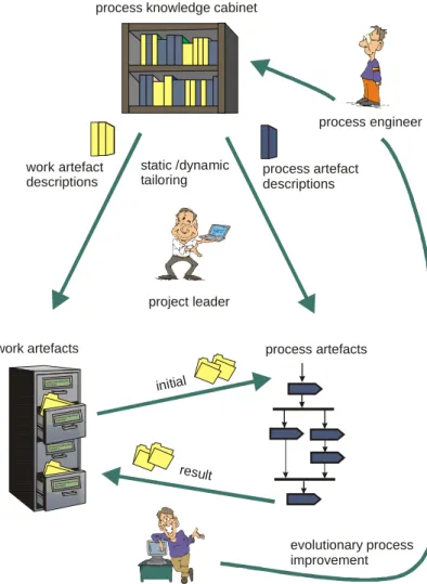
Developing and maintaining software is a challenging task. Thus, a well-defined software engi-neering process promises guidance for the whole project team. A living software development process comprises a set of predefined building blocks for software processes, which serve as an organization-wide standardized process model outline adaptable to various project situations. Additionally, it offers the ability to incorporate new process knowledge. Therefore, a living software development process has to support three different kinds of adaptation, namely static tailoring, dynamic tailoring and evolutionary process improvement. In this section we intro-duce these kinds of process adaptation. We discuss the according roles performing these adap-tations as shown in Figure 1, namely the project leader, the software engineer,and the process engineer.
The project leader is responsible for selection and tailoring of a suitable development process that fits to the specific needs of his project. The process knowledge cabinet provides the set of organization’s approved and standardized work artefact descriptions, i.e. descrip-tions of all kinds of documents that are produced or needed throughout the development proc-ess. Further it provides a set of process artefact descriptions, i.e. descriptions of development activities and guidelines to perform these activities. Thus the process knowledge cabinet con-tains the building blocks that form the organization’s standardized process model.
When setting up a project the project leader can use these building blocks. Thereby, the project leader defines what the expected results (the work arte-facts) of the project will be and
how the project team will cre-ate these work artefacts follow-ing the guidelines provided by process artefact descriptions. As depicted in Figure 1 every process artefact description contains the definition of the set of work artefacts, which are a prerequisite for the applica-tion (initial work artefacts) as well as the set of work artefacts created or modified during the execution of the process arte-fact (the result work artefacts). For example, a process artefact description that explains how to find test cases might require a “Use Case Document” as initial work artefact and create a “Test Case Document” as a result work artefact.
The activity of composing an individual process for a new
project at the beginning of the project is called static tailoring. Whenever the project’s envi-ronment or requirements change, the project leader has to reconsider the assembled develop-ment process. This may result in a reconfiguration of the process, although the project is already running and some results may have been created. Enabling such a dynamic tailoring is one the most important features of a living process. It enables the project leader to take un-planned and incalculable changes of the project environment into account. For instance, the project leader has the ability to choose among several alternative strategies for performing a certain development activity. Thus, the project team may be guided by some coarse-grained process artefact descriptions while details of the development process complying with the ac-tual project situation can still be adopted.
Imagine a project that starts up with some kind of waterfall process and later on it is dis-covered that external forces or changing customer requirements caused such big changes that the chosen process is not practicable any more. In our living process the execution of a certain process artefact does not depend on the successful execution of any preceding process arte-facts but only on the existence of the necessary work artearte-facts in the appropriate state. Thus, a project team is not obliged to follow the waterfall process gradually up to the end. Instead it can reconfigure the entire process by selecting an appropriate course grained process artefact like the spiral model (Boehm, 1986) for example and enter the new process at the stage
deter-Architectural Alterna ti ves De scrip tion Architectural Alternatives Descrip tio n work artefact descriptions work artefacts evolutionary process improvement process engineer initial result process artefacts static /dynamic tailoring
process knowledge cabinet
process artefact descriptions software engineer project leader Architectural Alternatives Descri pti on Arc hi tec tura l Alternati ves Description
mined by the state of the work artefacts produced so far.
Once the project leader has defined the development process, the software engineers apply this process. They follow the scheduled flow of development activities represented by the se-lected process artefact descriptions. For each application of a process artefact description the software engineer requires a set of initial work artefacts and produces several result work arte-facts as shown in Figure 1. Consequently an organization’s best practices are documented as process artefact descriptions.
The experiences gained by the software engineers as well as the project leaders’ are valu-able feedback for the process engineer. He is concerned with the definition and maintenance of the entire process model represented in the process knowledge cabinet. The living software development process model facilitates a continuous improvement of an organization’s standard development process. We call this practice evolutionary process improvement.
The task of maintaining a process knowledge cabinet is one of the most critical ones for the long-term success of an organization. A process engineer has to ensure that adding, chang-ing or removchang-ing process elements does verifiably improve the process. Therefore two major criteria have to be considered: First it has to be ensured that a new or modified process frag-ment does bring benefit in a certain situation. Secondly the process engineer has to classify the new artefact in a way that a project leader does apply it only in situations where it is appropri-ate.
The first issue is usually ensured by the fact that changes of the process model generally result from feedback that software engineers provide. Since the software engineers are the people that actually apply the process fragments, their experience is the most valuable. Further a project leader might likewise provide feedback on process artefacts by measuring their effi-ciency using well-defined metrics and evaluation techniques. Such software process quality metrics are not in the focus of this work, but there exist a huge number of publications and approaches to measure the efficiency of a development process. Examples for process quality measurement approaches can be found in (Rout 1998) and (Schramke 2002).
The second issue of classifying process fragments is at least as important as the first one. So introducing a brilliant new approach for testing information systems could be extremely disadvantageous when it is applied in an inappropriate project context, like the development of an embedded system. Therefore a process engineer has to provide a profile for every process artefact that allows project leaders to compare their projects’ characteristics with the given profile and thereby deduce weather the artefact is applicable in their situation or not. The au-thors applied an approach where a project evaluation sheet is filled in by project leaders. Fur-ther, every process fragment comes with a project evaluation profile that can be automatically compared with the project evaluation to rate the process fragments applicability in the given situation. The applied project evaluation, which is not a major topic of this paper, is based on the work presented in (Schramke 2002) and (Wildemann 2001). Again the software engineers’ experience is a valuable source of information for a process engineer to determine sensible profiles for process fragments.
3 Process Models and Meta-Models
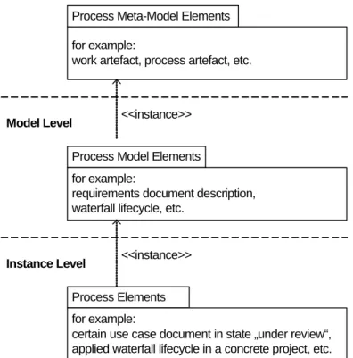
According to (Finkenstein1994) and (Conradi 1992) a software development process can be divided into a produc-tion process performed by software engineers, compris-ing the development and maintenance of work arte-facts, and a meta process performed by process engi-neers, that deals with the maintenance and evolution of the software development process itself. Since we de-veloped a language to express the concepts of this meta process, our proposed model consists of three levels as illustrated in Figure 2. This layered model integrates the different views on the soft-ware development process according to the different roles identified in the previous section.
We use this meta-model
structure according to the guidelines provided by the Meta Object Facility (MOF) specification (OMG, 1999). These levels are not levels of abstraction but meta-layers. Every layer is de-scribed in terms of the language defined in the level above. The top level layer is dede-scribed using a common accepted language, like UML class diagrams (OMG, 2001).
The lowest level, the instance level, captures the elements belonging to a concrete project, such as an analysis document in a certain state or a currently applied waterfall process. Soft-ware engineers operate on this level since they are concerned with concrete work artefacts and perform the required processes and activities.
The model level provides model elements to assemble a tailored and customized develop-ment process. Therefore project leaders use their organization’s process knowledge cabinet (see Figure 1), which is located on the model level. For example, the model level may contain a description of the purpose and structure of an analysis document, a description of the waterfall lifecycle model and a description of a method for testing. Thus, project leaders use the model level to define how software engineers should perform their tasks and what kind of work prod-uct instances have to be produced.
The meta-model level provides the basic notions and concepts of the living software de-velopment process. It offers clear definitions for terms like „Work Artefact Description” or “Process Artefact Description”. Process engineers use these notations and concepts to describe
for example:
work artefact, process artefact, etc.
Meta-Model Level
Model Level
Instance Level
Process Meta-Model Elements
Process Model Elements
Process Elements for example:
requirements document description, waterfall lifecycle, etc.
for example:
certain use case document in state „under review“, applied waterfall lifecycle in a concrete project, etc.
<<instance>>
<<instance>>
Figure 2: Overall model of the living software development process
the elements of their organization’s process knowledge cabinet, which are located on the model level. Thus process engineers use the meta-model level to specify a standardized devel-opment process as required on level three of the Capability Maturity Model (CMM) (Paulk, 1993).
4 A Meta-Model for Software Development Processes
In this section we introduce the essential concepts and elements of the proposed meta-model, imposing the structure and abilities of the underlying model and instance levels. According to Figure 1 we distinguish between two types of process model artefacts: work artefacts and process artefacts.
Work artefacts are all kinds of documents that are produced or needed throughout the de-velopment process. An example of a work artefact is a system specification document. It might itself be composed out of several other work artefacts, e.g. a set of use case documents and test cases. A system specification can be considered as a first order work artefact. Another kind of work artefacts are relationships between themselves. For example a test case specifica-tion may be related to a use case document proving the use cases’ correct implementaspecifica-tion. To document a development process we have to describe all these different types of development documents as well as their relationships using work artefact descriptions.
Process artefacts on the other hand are development tasks of any granularity which are performed during software development to produce new or to modify existing work artefacts. Usually existing work artefacts are needed to perform certain tasks. Testing is an example of a process artefact that requires a component implementation and a test specification document as input and generates a test report as output. Analogous to work artefacts, we describe process artefacts in terms of process artefact descriptions.
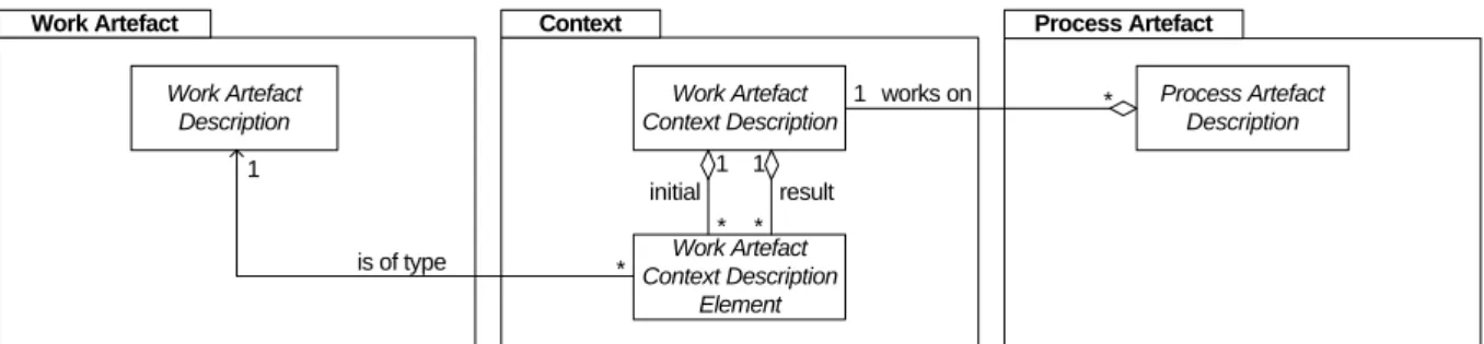
Work Artefact Description Work Artefact Work Artefact Context Description Work Artefact Context Description Element 1 1 * * initial result Context Process Artefact Description Process Artefact works on 1 * is of type * 1
Figure 3: Conceptual overview over the process meta-model
Accordingly, process artefact descriptions and work artefact descriptions are the key ele-ments of the proposed meta-model. Figure 3 shows an UML class diagram which captures an overview of the proposed meta-model. The Work Artefact package contains the class Work Artefact Description. An instance of this class represents a description or a template of a cer-tain work artefact type.
Work artefacts can be seen as the static part of a development, whereas process artefacts cover the dynamic aspects. The Process Artefact package in Figure 3 contains the class Proc-ess Artefact Description. Process artefact descriptions define all types of process artefacts, e.g. whole development processes, sub-processes or even atomic development activities. A process artefact description explains how a process is applied.
Static and dynamic tailoring means (re-)composition of work and process artefacts. Modu-larity and clear, well-defined interfaces between work and process artefacts are required in order to support the two tailoring concepts. Therefore a process artefact’s interface must state in which project situation this artefact is a suitable “next step” and to which situation this step leads us.
The Context package contains the concepts to define the required interfaces by relating process artefacts with work artefacts. With the concept of context we can describe how a set of work artefacts is affected by the application of a process artefact. Each process artefact description refers to exactly one Work Artefact Context Description which relates an initial
context with a result context. A work artefact context description – context description for short – determines which work artefacts are required, changed or produced when a given process artefact is executed. For example, a process artefact description “Validate Use Cases” might require work artefacts of the types “Use Case Document” and “Test Specification Document” as input. The result of the application might be a new work artefact description “Test Report”.
Context descriptions enable the project leader to reconfigure the development process by choosing different process artefacts based on already elaborated work artefacts during project execution. It is possible to capture complex context descriptions by modelling dependencies between required, produced, and modified work artefacts. For instance, one can express changes of the status of work artefacts or how newly created work artefacts of the result con-text are related with work artefacts of the initial concon-text.
5 The Meta-Model in Detail
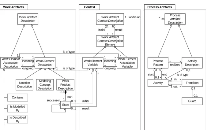
Work Artefact Description Work Element Description Work Element Association Description Work Product Description Modeling Concept Description Notation Description Contains Is Modelled By Is Described By State successor * * incoming outgoing 1 * * 1 Work Artefacts 0..1 1 start 0..1 0..1 Work Artefact Context Description Work Artefact Context Description Element Work Element Variable Work Element Association Variable incoming outgoing 1 * * 1 1 1 * * initial result is of type is of type Context Process Artefact Description Activity Description Process Pattern Activity Transition Guard Process Artefacts works on 1 * 1 1 0,1 * start end in out 1 * * 1 1 0,1 * is of type 0,1 * * realizes * * 1 1 * * initial result
The process metamodel introduced in the previous section comprises three basic concepts -process artefacts, work artefacts, and contexts. In the following sections we will have a closer look into each package and refine our meta-model to a degree that enables us to apply the proposed concepts.
As shown in Figure 4 we have specialized the rather general umbrella terms of Figure 3 into a set of concrete meta-model elements and as you may have noticed the “is of type” asso-ciation has now been refined into concrete assoasso-ciations between classes that inherit from the abstract classes with the original association.
5.1 The Work Artefact Package
Work Artefact Description is the most general concept of the Work Artefact package shown in Figure 4. Based on this concept, process engineers should be able to describe the whole prod-uct model of their organization’s software development process. Consequently, a process en-gineer must be able to describe the work artefacts themselves and the relationships between them. For those reasons we distinguish between two kinds of work artefact descriptions: The
Work Element Description represents the definition of product model elements and the Work Element Association Description represents different kinds of associations that may exist be-tween work elements. This could be a hierarchical structure of the product model itself but also other relationships like for instance logical dependencies between single work artefacts.
Furthermore, we classify the work element descriptions into
Work Product Description, Model-ing Concept Description and
No-tation Description. The work
element association descriptions between the different types of work artefact descriptions are categorized in Contains, Is Mod-elled By, Is Described By, Derived From, or Successor. Note more classifications may exist. They can be easily added by sub-classing as illustrated in Figure 4.
Work Product Descriptions
record the purpose and appearance of work products, which are the documents produced by a devel-opment project. Such a description may also contain some examples
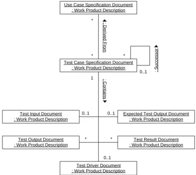
and templates for the kind of document it specifies. An instance “Test Case Specification Document” of a Work Product Description may for example determine the structure and intent of test case specifications and provide an empty template for test case specifications.
As shown in the instance diagram in Figure 5, a set of “Use Case Specification Docu-ments”, which is again an instance of the class Work Product Description, may be the source
Use Case Specification Document : Work Product Description
Test Case Specification Document : Work Product Description
Test Input Document : Work Product Description
Test Output Document : Work Product Description
Expected Test Output Document : Work Product Description
Test Result Document : Work Product Description
: C o n ta in s * * * 0..1 1 0..1 0..1 * *
Test Driver Document : Work Product Description
0..1 : D e riv e d F ro m : S u c c e s s o r
Figure 5: Sample product model definition for test specification
for a set of “Test Case Specification Documents”. This n-to-m relationship between “Use Case Specification Documents” and “Test Case Specification Documents” is an instance of the class
Derived From. For instances of association classes we use the short notation in form of asso-ciation lines and an associated text referencing the class name of this instance (cf. Figure 5).
Furthermore, an association of the type Successor indicates that a set of “Test Case Speci-fication Documents” may be ordered in a certain manner. A “Test Case SpeciSpeci-fication Docu-ment” has to contain a “Test Input DocuDocu-ment” and an “Expected Test Output DocuDocu-ment”, as shown with the association type Contains. The test case execution procedure itself is deter-mined in the “Test Driver Document”. For each test case execution a “Test Output Document” and a “Test Result Document” are assigned to the “Test Case Specification Document”. The “Test Result Document” contains a comparison between the “Expected Test Output Docu-ment” and the produced “Test Output DocuDocu-ment”.
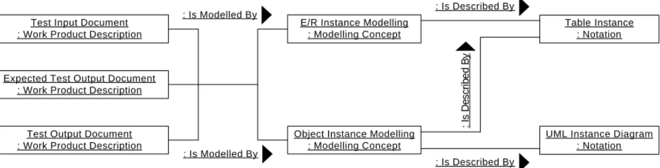
For each work product description the process engineer can explicitly determine what kind of modeling concepts may be used to describe an instance of this work product. As an exam-ple, the work product “Test Input Document” shown in Figure 5 must contain a complete start state description of the system under test. The work product “Expected Test Output Docu-ment” contains a complete expected end state description of the system under test. Finally, the work product “Test Output Document” contains a complete end state description as a result of a system test execution. Hence, all three work products contain different information, but the description of this information can be modeled using identical modeling concepts.
As shown in Figure 6, these three work products can be modeled by either using the mod-eling concept “Object Instance Modmod-eling” or using the modmod-eling concept “Entity/Relation In-stance Modeling”. For each modeling concept we can further determine the notations one may use. The modeling concept “Object Instance Modeling”, for example, may be described using the notation “UML Instance Diagram”. The modeling concept “Entity/Relation Instance Mod-eling” may be described using the notation “Table Instance” or again the notation “UML In-stance Diagram”. Hence, different work product descriptions can make use of the same modeling concepts and in some situations different modeling concepts can even make use of the same notations (cf. Figure 6).
Test Input Document : Work Product Description
E/R Instance Modelling : Modelling Concept
Object Instance Modelling : Modelling Concept
Table Instance : Notation
UML Instance Diagram : Notation Test Output Document
: Work Product Description Expected Test Output Document
: Work Product Description
: Is Modelled By : Is Modelled By : Is D e s c ri b e d B y : Is Described By : Is Described By
Figure 6: Example with different modeling concepts and notations for test input descriptions
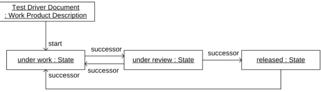
As shown in Figure 4 every work product description comprises a State. This is the initial state the work product has when it is created. The state of a work product instance may change by the application of process artefacts. The association successor indicates that for every state a set of reachable successor states may exist. Thus we use a non-deterministic finite automate that determines the lifecycle of the work product instances in terms of their possible
states, like shown in Figure 7.
Test Driver Document : Work Product Description
under work : State under review : State released : State start
successor
successor
successor
successor
Figure 7: Example of a state model associated to test case specifications
In this example the work product description “Test Driver Document” determines that every test case specification initially has the state “under work”. There is one possible succes-sor state “under review” that can be reached when the specification is reviewed. If the specifi-cation passes the review its state alters to “released”, otherwise it is set to “under work” again. Whenever a released specification is changed, its state is set to “under work” again until it has passed another review process.
To sum up, the meta-model in Figure 4 provides all the necessary building blocks to en-tirely describe a product model for a development process. Having a clearly defined product model is an essential prerequisite for the integration of different process artefacts during static and dynamic tailoring as we will see in the following sections.
5.2 The Process Artefact Package
A software development process and the corresponding activities are described in terms of the
Process Artefact package (cf. Figure 4). We distinguish between two types of process artefact descriptions, namely Process Patterns and Activity Descriptions.
Instances of Process Patterns describe fragments of a software development process and, to be particular, they describe the causal ordering of single Activities. To assure software qual-ity, for example, a regression capable test suite for the software system under development might be a good idea. Therefore a software engineer has to create test case specifications fol-lowing the appropriate product model definition in Figure 5. For each test case he has to spec-ify the test input and the expected test output. All these specifications must contain the complete status of the system under test. In the case of a business information system, the status is given through the data in the corresponding database.
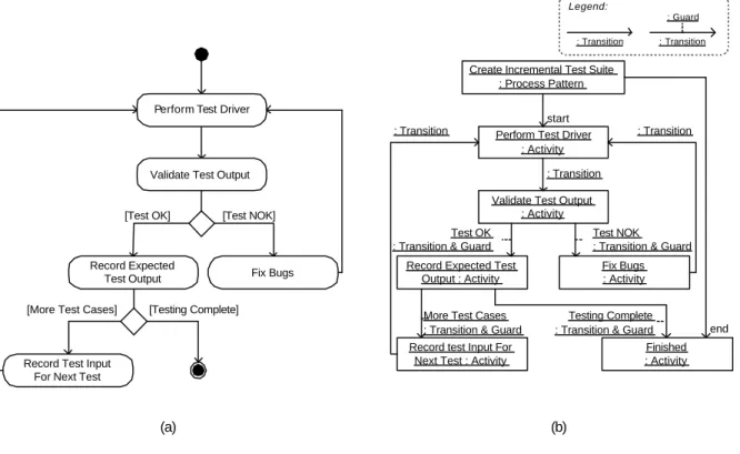
In Figure 8 (a) we see an example of a process fragment for the incremental automatic creation of test input and expected output data in form of an UML activity diagram. The basic idea is to use the produced test output data as input for a subsequent test (cf. Bonfig, 2000).
In the example it is assumed that one has already specified a sequence of “Test Case Specification Documents”, where each test case can consume its predecessors output as test input data. The process starts with performing the activity “Perform Test Driver” that obvi-ously produces a work artefact “Test Output Document” (cf. Figure 5). This test output de-scription has to be validated manually and either a discovered bug has to be fixed (“Fix Bugs”) or the test output data is recorded in an “Expected Test Output Document”. If a successor for the test case exists, the “Expected Test Output Document” serves as “Test Input Document”
for this test, otherwise the application of the process fragment is completed and a complete regression ready test suite is available.
[Test OK] [Test NOK]
[More Test Cases] [Testing Complete]
Perform Test Driver : Activity Create Incremental Test Suite
: Process Pattern
Validate Test Output : Activity
Fix Bugs : Activity Record Expected Test
Output : Activity
Record test Input For Next Test : Activity
Finished : Activity start
end Test OK
: Transition & Guard
Test NOK : Transition & Guard
More Test Cases : Transition & Guard
Testing Complete : Transition & Guard
(a) (b)
: Transition
Legend:
Perform Test Driver
Validate Test Output
Record Expected Test Output
Record Test Input For Next Test
Fix Bugs
: Transition : Transition
: Transition
: Guard
: Transition
Figure 8: A sample process fragment
In Figure 8 (b) this process is described in terms of our meta-model with the process pat-tern “Create Incremental Test Suite”. As defined in Figure 4 a process patpat-tern comprises a number of Activities that are to be executed during its application. The sequential ordering of these activities is expressed by connecting them with Transitions. Alternative paths can be specified by annotating Transitions with Guards expressing certain conditions. Like the guard in Figure 8 (b), which specifies that the Activity “Record Expected Test Output” will only be executed if the result of the Activity “Validate Test Output” is “Test OK”?
Please note that Figure 8 (b) only depicts instances of the Activity class from our meta-model. Instances of Transition and Guard are shown as association instances to keep the dia-gram readable. Since the meta-model in Figure 4 allows us to specify multiple transitions that lead in and out of an activity, forks and joins can also be expressed. However, UML activity diagrams are a good and sufficiently powerful notation to graphically depict the flow of activi-ties within a process pattern.
Such an activity diagram is usually part of a process pattern’s description. It depicts all ac-tivities that have to be performed and their causal dependencies. In addition a process pattern contains a textual description for every activity that explains the process step in detail. When-ever a process engineer does not want to determine how a certain Activity, like testing, is per-formed but wants to ensure that it is performed, he might refer to an Activity Description
“Testing” instead of providing a textual description of the activity. In this case a project leader is free to choose an appropriate process pattern that realizes the activity description to be exe-cuted within the project (cf. Figure 4).
Thus, Activity Description serves as a placeholder or common term for an activity that is well-known by all users of the knowledge base. It determines only what kind of activity has to
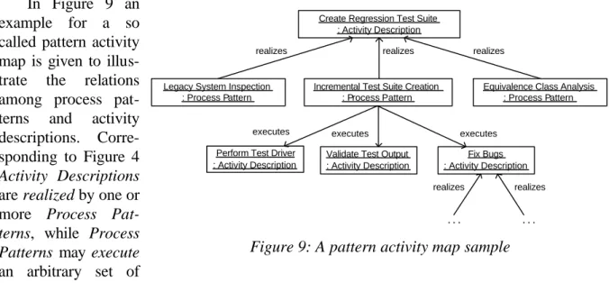
be performed. The description of how an activity is performed is defined as a process pattern. In Figure 9 an
example for a so called pattern activity map is given to illus-trate the relations among process pat-terns and activity descriptions. Corre-sponding to Figure 4
Activity Descriptions
are realized by one or more Process Pat-terns, while Process Patterns may execute
an arbitrary set of
Activity Descriptions. This executes relation is determined by the is of type relation of the Ac-tivities, which are contained in the Process Pattern (cf. Figure 4). Those Activities can be ap-plied by performing any Process Patternrealizing the Activity Description.
In this example the realizes association between the process pattern “Incremental Test Suite Creation” and the activity description “Create Regression Test Suite” determines that this pattern can be used to fulfill the corresponding activity. Of course there may exist alternative patterns to create regression test suites, e.g. “Legacy System Inspection” that uses existing legacy software to generate valid test data.
This kind of indirection may seem confusing at the first glance. However, it provides a very powerful and flexible mechanism. Wherever there is more than one alternative method to achieve a certain development goal one can now set an activity description as a place holder to tell a developer that he may choose among a set of alternative practices. This allows a project leader to use coarse grained patterns at the beginning of a project to sketch a rough process outline. Later on a project team may choose among more detailed patterns to perform smaller tasks adequately to the actual situation.
So far we have not stated when a process pattern may realize an activity description with-out violating consistency constraints. For example, we would expect from every pattern that realizes the activity description “Incremental Test Suite Creation” that it does produce a set of “Test Input Documents”.
Furthermore we would like to provide guidelines when a certain process artefact is appli-cable in a running project and when not. Applying a certain pattern always has benefits and drawbacks. A detailed discussion of the problem domain, the context and the pros and cons in the consequences part of a process pattern are essential elements of a pattern. For that reasons a process pattern comprises a set of attributes that are not shown in Figure 4.
These attributes define a common template for process patterns that intentionally has simi-larities to the templates used to describe patterns in (Gamma, 1994) or (Buschmann, 1996). The basic elements of such a pattern template are shown in the appendix in Section 10. A process pattern description based on this template provides the needed information for less experienced project leaders to elaborate the best possible development process for their project
Create Regression Test Suite : Activity Description
Incremental Test Suite Creation : Process Pattern Legacy System Inspection
: Process Pattern
Equivalence Class Analysis : Process Pattern
Validate Test Output : Activity Description Fix Bugs : Activity Description executes executes realizes realizes realizes realizes realizes . . . .
Perform Test Driver : Activity Description executes
by static and dynamic process tailoring of the process knowledge cabinet (cf. Section 2).
5.3 The Context Package
While process artefact descriptions define how development tasks are performed, work arte-fact descriptions determine the structure of the work product model that is modified by per-forming these development tasks. The Context package in Figure 4 provides a clear and expressive interface between these two concepts organizing their complex dependencies.
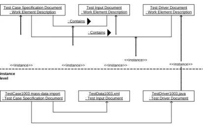
Consider the product model definition for test specifications in Figure 5 and the corre-sponding process pattern “Incremental Test Suite Creation” in Figure 8. We assume that three of these work products have already been created in a fictitious development project. As shown in Figure 10 the test case specification document with the name “TestCase1003 mass-data import” has been elaborated containing the two documents “TestData1003.xml” and “TestDriver1003.java”. These work products are instances of the corresponding classes of the work product model defined on the model level (see also Figure 5).
As discussed in the previous section, the execution of a process pattern’s activity may re-quire necessary work products as input. To perform the first activity description “Perform Test Driver” of the sample process pattern (cf. Figure 8), for example, we have to ensure that in-stances of the work element descriptions “Test Case Specification Document”, “Test Input Document”, and “Test Driver Document” exist. Furthermore, we have to make sure that these instances are associated forming a consistent test case specification document. Hence, the documents for the test case specification shown in Figure 10 on the instance level as well as in Figure 11 (a) provide the required work products to perform the activity description “Perform Test Driver”.
Executing this activity de-scription will cause an update of the overall development products and produce some new work products. Figure 11 (b) indicates the new or modified work prod-ucts as shaded gray boxes. Fur-ther, newly created work product associations are depicted by dashed lines: The work product “TestOutput1003_20020814.log” has been created while perform-ing the test driver. This work product has been associated to the document “TestCase1003 mass-data import” that servers as folder for all work products re-lated to the corresponding test
case. Hence the folder document itself has also been marked as modified.
To sum up, necessary input work products have to be available to perform an activity de-scription contained in a process pattern or to execute a process pattern itself. After performing an activity description or a process pattern, work products have been created and modified. To
Test Case Specification Document : Work Element Description
TestCase1003 mass-data import : Test Case Specification Document
Test Input Document : Work Element Description
Test Driver Document : Work Element Description
TestData1003.xml : Test Input Document
TestDriver1003.java : Test Driver Document model
level
instance level
<<instance>> <<instance>> <<instance>> <<instance>>
<<instance>> : Contains
: Contains
Figure 10: Sample test case specification in a fictitious development project
provide a clear and precise interface between work artefacts and process artefacts the pro-posed process meta-model must be capable of describing required input and produced output work products. The union of required input and produced output is the Work Artefact Context Description (cf. Figure 4). It describes the prerequisites and the effect of activity description and process pattern application. The prerequisites are contained in the initial subset of the class
Work Artefact Context Description Element. The effects are contained in the result subset. The inherited classes Work Element Variable and Work Element Association Variable are the essential elements to describe initial and result work artefact sets. These variables allow defining a product model pattern that consists of typed place holders. This pattern may match a concrete product model of a development project or not and thereby indicate if the corre-sponding process artefacts can be applied on the product model of this development project.
Figure 12 shows the initial work artefact context description of the discussed activity “Perform Test Driver” based on work element variables. Three work element variables with the corresponding work element association variables are shown with bold lines on the right side. Each variable is typed, i.e. it is related to the corresponding work element description or work element association description pictured with bold lines on the left side of Figure 12.
Based on this work artifact context description it can be decided if the activity “Perform Test Driver” can be performed on the products of a concrete development project. As an ex-ample, the product model shown on the instance level of Figure 10 matches the work artefact context description in Figure 12: first, each variable in the context specification can be bound to a corresponding work product with the same type and, secondly, the structure of these work products matches to the structure of the context description. Hence, the activity is applicable on this product model instance. Additionally, every work variable may further constrain the application of activities and process patterns by specifying the initial and result state of the required work elements (cf. Figure 4).
In summary, the concept of work artefact context descriptions is one of the major advan-tages of the proposed meta-model in comparison to existing process meta-models. It allows us to explicitly determine if a process artefact is applicable and what its effects on the work prod-uct model are. Moreover, it specifies whether a process pattern is capable to realize an activity description or not. A process pattern can only realize an activity description if the pattern’s
TestCase1003_mass-data import : Test Case Specification Document
TestDriver1003.java : Test Driver Document
TestCase1003_mass-data import : Test Case Specification Document
TestData1003.xml : Test Input Document
TestDriver1003.java : Test Driver Document
TestOutput1003_20020814.log : Test Output Document
(a) (b)
: Contains
: Contains
TestData1003.xml : Test Input Document
: Contains : Contains : Contains
initial work artefact context description is a subset of the activity description’s initial work artefact context description and the pattern’s result work artefact context forms a superset of the activity description’s work artefact context.
Figure 12: Sample product model specification for the activity "Perform Test Driver"
6 Related Work
Our approach is based on the concept of process patterns (Bergner 1998a, Bergner 1998b), as its basic idea of integrating different process fragments obviously seems to correlate with the requirements of a living software development process.
Important contributions in the area of patterns, as for example process and organizational patterns, have also been made by Ambler, Coplien and Cockburn (Ambler 1998, Ambler 1999, Coplien 1994, Cockburn 1997). These approaches are lacking a formally defined process meta-model enabling dynamic reconfiguration of the process and providing a common language for process engineers for process improvements.
Our approach differs from existing process models, such as the Objectory Process (Jackobson 1992), the Unified Software Development Process (Jacobson 1999), the Catalysis Approach (D’Souza 1998), the V-Model 97 (Dröschel 1999), or eXtreme Programming (Beck 1999), as process patterns are modular building blocks. This enables a process model based on process patterns to be scalable, adaptable, changeable and extensible as required by the living software development process.
Recent approaches like the Software Process Engineering Meta-Model (SPEM 2002) are trying to provide a vehicle to process engineers for establishing a living process by defining a UML-based meta-model. As compared to our work, SPEM is suffering from several deficien-cies. Alternative paths in the process model can’t be modelled explicitly on different granularities as for example life-cycle or phase. Thus SPEM is sufficient to model exactly one process, which seems to be conflicting with the idea of continuous process improvement. Fur-thermore regarding work product descriptions, SPEM is lacking the concept of states and con-texts which are defined over work products and associations between them.
7 Conclusion
makes the software development more predictable and economic. Additionally, to survive in today’s highly dynamic markets a development process must be highly flexible and adaptable with respect to the frequent changes of system’s requirements and the environment in which it is applied.
While existing process models do support static tailoring there is usually no support for dynamic tailoring, the procedure of adopting and reconfiguring a development process while it is actually running. In order to overcome the methodical lack and to support static and dy-namic tailoring, similar to software systems, modularity and clear, well-defined interfaces be-tween work and process artefacts are required. Therefore the presented meta-model provides the concept of work artefact context descriptions, a mechanism to define clear interfaces be-tween work and process artefacts.
Furthermore, the presented approach supports evolutionary process improvement of an organization’s process knowledge cabinet. The concept of alternative process patterns that realize development activities promotes this feature in a very comfortable way. Without chang-ing any existchang-ing process artefact of our knowledge cabinet we can seamlessly integrate new process patterns. When needed we can also refine existing process patterns by introducing new development activity descriptions for existing activities to allow additional alternative sub-processes.
However, further work is still necessary. We need to provide methodical guidelines for process engineers when a process should be changed and how much. Process engineers can integrate new process patterns into our current process cabinet. Dynamic tailoring enables project leaders to immediately use new process patterns. If the new process pattern hasn’t showed the desired success, you can roll-back your modifications and keep on going with the original development process. This enables us to test small improvement steps minimizing the risk of introducing new processes. Thereby we can define how much we will change in the process cabinet, and as important benefit, the old process parts still exist in the cabinet.
Moreover methodical guidance for the development and the application of the presented pattern based approach is still needed. Finding the correct granularity and the correct level of abstraction for processes and work artefact descriptions is one of the most important tasks for software process engineers that build up and maintain an organization-wide process knowledge repository according to the presented meta-model. Further developers need advice in choosing the right process fragments during development and in producing appropriate work artefacts. Since these issues are already addressed by our process meta-model, such a methodical guid-ance for the user is rather simple to realize. The authors are currently applying the concepts of the living software development process and are developing a methodology for pattern-based software process engineering based on these experiences.
Finally, a proper tool infrastructure is a prerequisite to gain maximal profit from the flexi-bility the concept of the living software development process offers. Such a tool must support process engineers defining and maintaining his organization’s standardized process knowledge cabinet. It serves as a knowledge repository for development processes and it allows browsing and managing product models and processes. A tool support is especially helpful to ensure consistency among the artefacts. The tool LiSa (LiSa 2002) is a prototypical realization of such a process knowledge repository. Beyond allowing the definition of process models ac-cording to the meta-model with a comfortable, web-based interface, the tool can also serve as an access point for projects to their organization’s process knowledge base. A user may
browse through the different artefact descriptions or search for descriptions that meet the crite-rions of his project.
The next step towards supporting the living software development process is a tool, which provides tool support for project leaders and their developers. For instance the prototype tool APE (APE 2002) does not manage process element descriptions but their instances, namely work artefacts in a project. The process definitions that were created with LiSa are used to instantiate work products of the correct type and to ensure a process execution according to the steps defined in the process knowledge repository by offering alternative methods for mas-tering upcoming tasks. In order to guide software engineers in their daily work, APE is cur-rently developed as an integrated part of the Eclipse integrated development environment (Eclipse 2002).
All these parts together, a well-defined process meta-model, a comprehensive tool support and the methodical guidance, finally enable the vision of a living software development process that is sufficiently flexible and well-documented to serve as an organization’s growing process knowledge base.
8 Acknowledgments
We are grateful to Klaus Bergner and Carsten Tauss for their valuable reviews of this article, to Manfred Broy and Alexander Ziegler for interesting discussions and comments, and to Inga.Küffer for finally polishing the article.
9 References
Ambler S. 1998. Process Patterns: Building Large-Scale Systems Using Object Technology. Cambridge University Press.
Ambler S. 1999. More Process Patterns: Delivering Large-Scale Systems Using Object Tech-nology. Cambridge University Press.
APE Software Technik Praktikum 2002. APE – Applied Patterns Environment. 2002. http://www4.informatik.tu-muenchen.de/~ape.
Beck K. 1999. Extreme Programming Explained: Embrace Change. Addison-Wesley.
Bergner K., Rausch A., Sihling M. and Vilbig A. 1998. A Componentware Development Methodology based on Process Patterns. Proceedings of the 5th Annual Conference on the Pattern Languages of Programs.
Bergner K., Rausch A., Sihling M. and Vilbig A. 1998. A Componentware Methodology based on Process Patterns. Technical Report TUM-I9823, Technische Universität München.
Boehm. B. 1986. A Spiral Model of Software Development and Enhancement. ACM Sigsoft Software Engineering Notes, Vol. 11, No. 4.
Bonfig T., Frömming R., Rausch A. 2000. GOAL - Eine Testinfrastuktur für unternehmens-weite Anwendungen. OBJEKTspektrum 4/2000.
Buschmann F., Meunier R., Rohnert H., Sommerlad P., Stal M. 1996. Pattern-Oriented Soft-ware Architecture, Volume 1: A System of Patterns. John Wiley & Sons.
Cockburn A. 1997. Survivng Object-Oriented Projects. Addison-Wesley, 1997.
Conradi R., Fernström C., Fuggetta A. and Snowdon R. 1992. Towards a Reference Frame-work for Process Concepts. In Lecture Notes in Computer Science 635, Software Process Technology. Proceedings of the second European Workshop EWSPT’92, Trondheim, Norway, September 1992, pp. 3-20, J.C. Derniame (Ed.), Springer Verlag.
Coplien J. 1994. A development process generative pattern language. In PLoP ’94 Conference on Pattern Language of Programming, 1994.
Cugola, G. and C. Ghezzi. 1998. Software Processes: a Retrospective and a Path to the Fu-ture. In Software Process - Improvement and Practice, 4, 101-123.
Derniame J.-C., Ali Kaba B. and Wastell D. (eds.). 1999. Software Process, Principles, Meth-odology, and Technology. Lecture Notes in Computer Science 1500, Springer.
Dröschel, W. and Wiemers M. 1999. Das V-Modell 97. Oldenburg.
D'Souza D., Wills A. 1998. Objects, Components, and Frameworks With Uml: The Catalysis Approach. Addison Wesley Publishing Company.
Eclipse – The Eclipse Project. 2002. http://www.eclipse.org
Finkelstein A., Kramer J. and Nuseibeh B. 1994. Software Process Modeling and Technology. Research Studies Press Ltd, JohnWiley & Sons Inc.
Gamma E., Helm R., Johnson R. and Vlissides J. 1994. Design Patterns – Elements of Re-usalbe Object Oriented Software. Addison Wesley.
Gnatz M., Marschall F., Popp G., Rausch A. and Schwerin W. 2001. Towards a Living Soft-ware Development Process Bases on Process Patterns. In Lecture Notes in Computer Science 2077, 8th European Workshop on Software Process Technology EWSPT, Witten, Germany. pp. 182-202. Ambriola V. (Ed.). Springer.
Henderson-Sellers, B. 1996. The need for process. In Object Currents – The monthly On-Line Magazine, December, http://www.sigs.com/publications/docs/oc/9612/oc9612.sellers.html. Jacobson I. 1992. Object-Oriented Software Engineering: A Use Case Driven Approach. Addi-son Wesley Publishing Company.
Jacobson I., Booch G., and Rumbaugh J. 1999. The Unified Software Development Process. Addison Wesley Publishing Company.
Kruchten P. 2000. The Rational Unified Process, An Introduction, Second Edition. Addison Wesley Longman Inc.
LiSa - A Living Software Development Process Support Tool. 2002. http://processpatterns.informatik.tu-muenchen.de
Object Management Group (OMG). 1999. Meta Object Facility (MOF) Specification. http://www.omg.org, document number: 99-06-05.pdf.
Object Management Group (OMG). 2001. Unified Modeling Language (UML). http://www.omg.org, document number: 01-09-67.pdf
Paulk M., Curtis B., Chrissis M.-B. and Weber C. 1993. Capability Maturity Model for Soft-ware, Version 1.1. Software Engineering Institute, CMU/SEI-93-TR-24, DTIC Number ADA263403.
Rout T. (Editor). 1998. ISO/IEC DTR 15504 (SPICE): Information Technology – Software Process Assessment
Royce W. 1970. Managing the Development of Large Software Systems: Concepts and Tech-niques. In WESCON Technical Papers, Western Electronic Show and Convention, Los Ange-les, Aug. 25-28, number 14. Reprinted in Proceedings of the Ninth International Conference on Software Engineering, Pittsburgh, PA, USA, ACM Press, 1989, pp. 328-338.
Schramke A. 2002. Situationsgerechte organisatorische Gestaltung von Softwareprojekten als Basis für eine erfolgreiche Projektdurchführung. Ph. D. Thesis at the Technische Universität München.
Software Process Engineering Metamodel (SPEM), Version 1.0 . Object Management Group (OMG). http://www.omg.org/technology/documents/formal/spem.htm. 2002.
Standish Group International, Inc. 2001. Collaborating on Project Success. Software Magazi-ne, February/March 2001. Wiesner Publishing. 2001.
Weinberg M. Gerald. 1997. Quality Software Management: Anticipating Change (Vol 4). Dor-set House.
Wildemann, H. 2001. Wandlungsfähige Netzwerkstrukturen als moderne Organisationsform: Anpassungsfähige Systemarchitekturen als Basis flexibler und wandlungsfähiger inner- und überbetrieblicher Auftragsabwicklungsprozesse. In: Industrie Management, May 2001.
10 Apendix
The following process pattern template serves as one possibility to document process patterns according to the proposed process meta-model.
Name: Name of the software development process pattern.
Also Known As: Other names for the pattern, if any are known.
Author: The names of the authors of the pattern.
Intent: A concise summary of the pattern’s intention and rationale.
Problem: The development issue or problem the pattern addresses, including a discussion of the associated forces. If possible, a scenario or a real world example is provided demonstrating the existence of the problem and the need for the pattern.
Context: The situation or state of a development project in which the process pattern may be applicable. The context comprises according to our meta-model the state of the required work artefact structure to apply the pattern – i.e. the initial and result state of the work artefact structure. Furthermore also external circumstances, influences and specific applicability pro-moters have to be considered here.
Solution: The suggested development process artefact including the development activities within the process pattern. The proposed solution may be described using textual as well as graphical description techniques.
Consequences: The benefits the pattern provides, and any potential liabilities.
Known Uses: Known uses of the pattern in development projects. These application examples illustrate the acceptance and usefulness of the pattern, and may provide practical guidelines, hints and techniques useful to apply the pattern, but also mention counter-examples and fail-ures.
See Also: References to patterns that solve similar problems and to patterns that help us refine the pattern we are describing. Not pattern-based sources may also be referenced.
11 Biography
Michael Gnatz studied Computer Science at the Technische Universität München where he received his diploma in 2000. Since 2000 he is working as a research assistant in the group of Prof. Dr. Manfred Broy at the Technische Universität München. Currently he is a member of a project, which aims at the integration of software development with other engineering disci-plines. His main interests are modeling of software development processes and process sensi-tive engineering environments.
Frank Marschall studied Computer Science at the Technische Universität München where he received his diploma in 1998. After a short period in software industry he works since 1999 as a research assistant in the group of Prof. Dr. Manfred Broy at the Technische Universität München. Currently he is a member of a project, which aims at the integration of software
development with other engineering disciplines, like machine development. His main interests are service-based software systems, system integration and software development processes.
Gerhard Popp studied Computer Science at the Technische Universität München where he received his diploma in 1999. Since 1999 he has been working as a research assistant in the group of Prof. Dr. Manfred Broy at the Technische Universität München. Currently he is a member of a project, which aims at the integration of software development with other engi-neering disciplines, like machine development. His main interests are security architectures and software development processes.
Andreas Rausch received his Ph.D. in 2001 from the Technische Universität München at the chair of Prof. Dr. Manfred Broy, with the dissertation titled "Componentware - Evolution-based Development of Software Architectures". He is part of the large interdisciplinary re-search project FORSOFT, leading the subproject ZEN that is concerned with the foundations of software engineering. He has been leading various industrial software projects, developing large distributed systems, and is one of the four founders of the software house 4Soft GmbH.
Wolfgang Schwerin studied Computer Science at the Technische Universität München where he received his M.Sc. in 1996. Since 1997 he has been working as a research assistant in the group of Prof. Dr. Manfred Broy at the Technische Universität München. Currently he is a member of a project, which aims at the integration of software development with other engi-neering disciplines. His main interests are software development processes for and the formal foundation of distributed systems.