A Guide to Good Practice in the
Specification and installation of
Contents
Section 1 - Introduction 1.1 Scope 7 1.2 Conservatory terminology 8 1.3 Responsibility 8 1.4 Customer contract 9 1.5 Reference guide to key stages 10Section 2 - Statutory requirements
2.1 Planning permission 11
2.2 Party wall act 17
2.3 Covenants 17
2.4 Right of light 17
2.5 Extra consents that may be required 17 2.6 Building regulations—England and Wales 18 2.7 Reference information 23
Section 3 - Site survey
3.1 Access and storage requirements 24 3.2 Evaluating the site 25 3.3 Ground assessment 27 3.4 Measurement survey 30 3.5 Other design specification requirements 32
3.6 Risk assessment 32
3.7 Reference information 32 Sample site survey sheets 33
Section 4 - Base design and construction
4.1 Loading 37
4.2 Ground movement 38
4.3 Site preparation and resistance to moisture 38 4.4 Special circumstances 38 4.5 Underground drainage and rainwater disposal 39 4.6 Substructure design 39
Contents
4.10 Soil stacks 53
4.11 Brickwork to DPC 53
4.12 Masonry wall construction 54 4.13 Damp-proof measures 56 4.14 Effect of a sloping site 56 4.15 Signing off base works 57 4.16 Reference information 57 Sample tender payment document 58
Section 5 - Superstructure design
5.1 Loading 59 5.2 Materials 61 5.3 Glazing 63 5.4 Environmental performance 64 5.5 Wall frames 69 5.6 Hardware 70
5.7 Above ground drainage 70
5.8 Weather tightness 72
5.9 Electrical safety 73
5.10 Fire safety 74
5.11 Protection from falling, collision and impact 74 5.12 Reference information 74
Section 6 - Superstructure Construction
6.1 Site control 75
6.2 Health and safety 75
6.3 Material storage 75 6.4 Superstructure installation 76 6.5 Follow-on trades 76 6.6 Finishing-off 77 Section 7 - Maintenance 7.1 Routine maintenance 78
Section 8 - The environment, waste management and re-cycling
Contents
Section 9 - Terminology 83
Section 10 - Bibliography and reference documents 86
Appendix A—Installation Inspection Report 95
Disclaimer 101
8.2 Waste management 81
Section 1 -Introduction
Section Contents 1.1 Scope 1.2 Conservatory terminal;ogy 1.3 Responsibilities 1.4 Customer contract1.5 Reference guide to key factors
This Good Practice Guide has been developed by the GGF’s Conservatory Asso-ciation (CA) Technical Group to help all those who purchase, specify, design, manufacture, supply and install Domestic Conservatories.
Most domestic conservatories are exempt from the majority of the Building Regulations in England and Wales, given certain provisos. It is these exempt conservatories that this Good Practice Guide aims to provide guidance for.
We have in mind future regulations and potential Inspection Bodies whose task it may be to enforce any regulations as they are deemed to apply.
The conservatory embodies considerable technology in the manufacture of the components and their correct assembly to produce a structure that can adequately resist the effects of imposed wind and snow loads. It must be appreciated that wind loads vary across the British Isles, from sheltered locations with low wind speeds, to those in highly exposed areas. Like-wise, snowfalls vary considerably across the country from south to north and west to east. The conservatory should be able to withstand the effects of driving rain while remaining wa-tertight throughout, including at the junction with the parent dwelling. Therefore the con-struction must reflect the likely exposure conditions and the imposed loads to be expected at any given location. A conservatory's thermal movements relative to the parent dwelling need to be allowed for, together with differences in ground movement with respect to seasonal changes in sub-soil water content.
Many conservatories are built in areas where underground drainage, gas supplies, electric ca-bles and water service pipes enter or run parallel with the dwelling. In these circumstances it is imperative that the underground services are not damaged, nor should such services in turn damage the conservatory. To meet this requirement the substructure of the conserva-tory will need to bridge over or otherwise suitably accommodate any service that runs be-neath. Alternatively it may be possible to divert the existing services around the new conser-vatory structure.
Conservatories by their nature perform differently than conventional extensions using con-ventional house construction. They will attract the beneficial solar heat gain and will provide a thermal buffer to the house during colder periods. In common with issues relating to the heating of dwellings, the type of occupancy pattern should be borne in mind in their design.
Section 1 - Introduction
1.1 Scope
This Good Practice Guide is designed to clarify and emphasise the good practices that are required for the successful installation of domestic conservatories.
This guide provides guidance on the statutory requirements and obligations of design and in-stallation and the good practices to be undertaken in the surveying and construction of base works.
To meet the conservatory exemption requirements detailed in the England and Wales Build-ing Regulations, this guide assumes that the conservatory will be separated from the parent dwelling by means of an externally rated physical barrier (containing doors, windows and/or walls)
It is anticipated that this document will assist in the training of all persons in the chain con-nected with the purchase and installation of the conservatory, from consumer to installer This Good Practice Guide provides recommendations for the construction of Conservatories, however these requirements are not mandatory. Details of mandatory requirements are de-tailed within Section 2, which covers Building Regulation and Planning requirements.
Section 1 -Introduction
1.3 Responsibility
All parties involved with the conservatory project should know their liabilities and responsi-bilities to ensure the conservatory is correctly designed, specified and satisfactorily installed.
The contracted retailer has overall responsibility for ensuring the suitability and compatibility of all components used on the installation, this includes the suitability of all glazing sealants with glazing materials and also the overall structural integrity and the integrity of the individual components used within the conservatory.
Section 1 - Introduction
The installation company should undertake a survey of the site prior to the manufacture of the conservatory. It may be necessary for the installation company to refer back to the fabricator of the components (this is often a different company), who in turn may need to refer back to the designer (again this can be a different company).
The construction of Conservatories is undertaken in key stages. However, it is essential that all of these stages are coordinated for the Conservatory to function correctly.
1.4 Customer contract
The product requirements and design specifications forms part of the customer’s contract/ schedule of works and should be signed by the customer and the retailer.
The responsibility for works carried out by persons other than the Contractor needs to be made clear, for example, if the contract for the construction of the base
is not included in the contract for the erection of the conservatory and is with another contractor.
As conservatories become more sophisticated and individually designed to meet the customer’s specific requirements, it is essential that the information gathered at contract and survey stage, is correctly recorded, interpreted and transferred to a specific customer drawing.
A copy of these drawings should be provided to the customer, the GGF also recommend that the customer have an opportunity to review and discuss these along with any other questions related to the construction of the conservatory.
It is important that the drawing variations should have been submitted to the client/ customer for their signature and approval. Any changes to be signed to avoid any misunderstandings in the future.
Tip:
Good communication is vital.
Always keep the customer informed,
even if just to say everything is on
Section 1 -Introduction
1.5 Reference guide to key stages
1. Be Aware of any statutory requirements · Planning permission
· Building regulations
· Safety, health and environmental requirements (SHE) Reference Section 2
2. Survey the site
3. Identify appropriate specification
4. Confirm detailed contract
5. Construct to agreed specification
· Ground assessment
· Site exposure
· Measurement survey Reference Section 3
· Design foundations, floors and walls
· Design wall frames and roof structure Reference Section 4 and 5
· Check relevant drawings and specification
· Obtain any statutory approvals
· Gain approval of design from customer Reference: Section 4 and 5
· Construct conservatory
· Verify construction is as agreed
· Issue any after care documentation Reference Section 6
Section 2 - Statutory Requirements
Section Contents
2.1 Planning permission 2.2 Party Wall Act 2.3 Covenants 2.4 Right of light 2.5 Extra consents 2.6 Building regulations 2.7 Reference information
The following requirements must be undertaken or taken into consideration when designing and constructing a conservatory:
General – Planning Permission and Building Regulations.
2.1 Planning permission
In England, this relates as to whether or not you can build a particular structure in a particular place and is concerned with the visual impact and size of the structure but not the technical integrity of the construction.
Under new regulations that came into effect 1 October 2008 adding a conservatory to a house may be considered to be ‘permitted development’, not needing an application for planning permission, subject to the limits and conditions below:
· No more than half the area of land around the 'original house'(2) would be covered by
· Additions or other buildings.
· No extension forward of the principal elevation or side elevation fronting a highway.
· No extension to be higher than the highest part of the roof.
· Single-storey rear extension must not extend beyond the rear wall of the 'original house'(2) by more than three metres if an attached house or by four metres if a detached house.
· Maximum height of a single-storey rear extension of four metres.
· Maximum depth of a rear extension of more than one storey of three metres from the rear wall of the 'original house'(Note 2) including ground floor.
· Maximum eaves height of an extension within two metres of the boundary of three metres.
· Maximum eaves and ridge height of extension no higher than existing house.
· Side extensions to be single storey with maximum height of four metres and width no more than half that of the original house.
Section 2 - Statutory Requirements
· On designated land(Note 1) no permitted development for rear extensions of more
than one storey and
· No cladding of the exterior walls and
· No side extensions.
Refer to diagrams to see how it works in England, Wales, Scotland and N. Ireland It should be noted that the replacement of an existing conservatory, even on a like for like basis may need planning permission. This must be checked with the local planning office before proceeding with the replacement conservatory.
Section 2 - Statutory Requirements
Note 1 – ‘Designated land’ includes National Parks and the Broads, Areas of outstanding Natural Beauty, conservations areas and World Heritage Sites
Note 2 – ‘Original Building’ means the house as it was first built or as it stood on 1 July 1948 (if it was built before that date). Although the current owner may not have built an extension to the house, a previous owner may have done so.
Contents
The planning requirements for permitted developments in Wales are similar to England but with some significant differences. The guidelines are detailed below:
(1) – The term ‘Highway’ includes all public roads, footpaths, bridleways and byways.
(2) – ‘Original Building’ means the house as it was first built or as it stood on 1 July 1948 (if it was built before that date). Although the current owner may not have built an extension to the house, a previous owner may have done so.
(3) – Highest part includes all finials and trims
(4) – Volume is measured externally
Please note that the above is given as a guide only and confirmation of rights under ‘permitted development’ must be checked with local planning office
Section 2 - Statutory Requirements
Please note that the above is given as a guide only and confirmation of rights under ‘permitted development’ must be checked with local planning office.
Section 2 - Statutory Requirements
Note 1 – The ‘original house’ is defined as the house plus any extensions as they stood 1 October 1973
Note 2 – If any existing extension to the original house or the proposed conservatory comes within 5 metres of another building belonging to the original house (e.g. garage, shed or greenhouse), the volume of that building will be treated as if it were part of the conservatory and counts against the allowance for additions and exten-sions.
Note 3 – If you live in a listed building or is in a conservation area, all additional buildings which are more than 10 cubic metres in volume, regardless of distance from the original house, are treated as extensions and reduce the allowance for extending without planning permission.
Note 4 – Any building added to the property which is more than 10 cubic metres in volume and within 5 metres of the house will be treated as an extension of the house, and so reduces the allowance for further additions to the house without planning permission.
Please note that the above is given as a guide only and confirmation of rights under ‘permitted development’ must be checked with local planning office.
For a terraced house (including an end of terrace), would the volume of the ‘original house’ be increased by more than 10% or 50 cubic metres (whichever is the greatest) by the proposed conservatory plus any other additions or buildings within 5 metres of the original house or additions?
For any other house would the volume of the ‘original house’ be increased by more than 15% or 70 cubic metres (whichever is the greatest) by the proposed conservatory plus any other additions or buildings within 5 metres of the original house and additions? For all buildings will the volume of the proposed conservatory plus any other additions or buildings within 5 metres of the original house or any
addition to that house be greater than 115 cubic metres? Will the conservatory be higher than the highest part of the original
house?
If the conservatory is within 3 metres of the boundary of the property, is it higher than 4 metres?
Is the property in a conservation area?
On any type of property, will the addition of the proposed conservatory plus any other extension built since 1 October 1973 plus any other garden building within the boundary of the property over 10 cubic metres,
increase the volume of the original house by more than 10% or 50 cubic metres, whichever is the greatest?
Have permitted development rights been removed by local authority by ‘Article 4 Direction’ or by other means such as covenants?
Is the property a flat or maisonette?
Is the proposed conservatory an addition to a listed building?
Permitted Development Planning Consent not required
Is the conservatory nearer to any road than the original house? Will more than half the land around the original house be covered by the
proposed conservatory plus existing additions and other buildings?
Check with local authority whether planning permission or listed building consent is required
Permitted Development Planning Consent not required
Section 2 - Statutory Requirements
2.2 The Party Wall etc. Act 1996
The Party Wall Act 1996 has effect from 1st July 1997 throughout England and Wales.
This Act comes under Civil Law and is not therefore administered or controlled by either the Planning or Building Control Departments.
If the conservatory construction affects or requires work directly on an existing shared wall, a neighbouring building on a boundary, the erection of a wall within 3 or 6 metres of a neighbouring building (dependant on depth of new foundations in relation to neighbouring foun-dations) or the erection of a wall on or adjacent to the property boundary, this Act may apply. An explanatory booklet is available from the local council offices, the Communities and Local Government direct, the CLG website or the planning portal website.
2.3 Covenants
Covenants or other restrictions in the title of the property, or conditions in the lease, may require someone else’s agreement before carrying out some kinds of work to your property. This may be the case even if no application for planning permission is required.
2.4 Right of light
Under the circumstances that Planning Permission is required there are guidelines that the local Authority may consider regarding “Right of Light” to an adjoining property’s existing windows. This consideration may limit the projection of the conservatory.
However, the “Right of Light” guide lines (45 degree Code) may be applied but these guide lines are not covered by Statute.
2.5 Extra consents that may be required
There may be extra consents that are required due to other factors, for example Water Au-thority Bye Laws. The following situations should be considered:
a) Local Authority consent b) Neighbours consent c) Original Builders consent d) Local Water Authority approval e) Restricted covenant
f) Conservation area consent g) Listed building consent
Section 2 - Statutory Requirements
2.6 Building regulations – England and Wales
A conservatory can be exempt from general Building Regulations (since 1985), provided it meets the following requirements –
· The conservatory is solely for domestic purposes
· The conservatory is single storey and built at ground floor level only
· The conservatory contains no sleeping accommodation
· The floor area is less than 30 square metres (internal floor)
· The construction of the conservatory does not require work to be completed on the existing drainage system e.g. moving sewage manholes etc.
· The conservatory must be separated from the existing property by a wall, an external rated door or glazed screen or combination of these elements, with the same or better thermal performance as the external walls of the rest of the original house
· The conservatory must not be connected to the house heating system, any heat-ing of the conservatory must be totally independent from the original house
It is important to note that although a conservatory may be exempt from building regulation control, the glazing in the conservatory must meet the requirements for safety glazing in criti-cal locations to either:
· Break in a way unlikely to cause injury
· Resist impact without breaking
· Be shielded or protected from impact
In practice this will mean using Safety Glazing Material in compliance with BS 6262 (shielding must protect both the inside and the outside of the glass) in critical locations in internal and external walls and roofs. Further details of how compliance can be achieved are contained in Approved Document N, Glazing – safety in relation to impact, opening and cleaning. Refer to diagram 5 to identify vulnerable glazing locations.
It may also be necessary to consider the need for containment glazing where the level difference between the finished floor of the conservatory and the external ground level is greater than 600mm. Details of how this can be achieved are contained in Approved Document K, Section 4: Guards and Barriers
If a new electrical circuit is being installed in a conservatory or an existing circuit servicing a kitchen or bathroom is extended, the works must be carried out by a member of a ‘competent persons scheme’ or notified to the building control department of the local authority. Additional sockets from an existing circuit may be fitted without reference to the above but it would be good practice to ensure they are protected by a suitable circuit breaker as they are likely to be used to extend power into the garden for mowers etc.
NB. It is a requirement for the GGF Conservatory Association Members that all glazing should conform to the requirements of BS 6262
Section 2 - Statutory Requirements
Diagram 5—Critical glazing location
If any part of a pane falls within the shaded zone the whole pane must be of Safety Glazing Material.
2.6.1 Modification to existing dwelling
Should the construction of the conservatory require material modification to the existing dwelling, i.e. change or addition of a structural opening, relocation of public drains (note that if there is a manhole within 3 metres of the proposed conservatory, check with the local wa-ter authority as they may require it to be moved), separate approval solely for the modifica-tions must be gained from Local Building Control. This type of work may be done under building notice approval rather than full plans approval.
Section 2 - Statutory Requirements
NB. Means of Escape
Where a conservatory is being installed, care must be taken to ensure that existing means of escape from the 1st floor level or from an inner room on
the ground floor, are not compromised by the addition of the conservatory. Alternatives means in accordance with Approved Document B must be con-sidered.
2.6.2 Permanent ventilation
Care must be taken when positioning the conservatory, it must be established whether any permanent ventilation for combustion appliances would be covered by the conservatory. These permanent ventilators provide air to ensure efficient combustion for open-flued appli-ances such as water heaters and in the case of flueless appliappli-ances, air to ensure efficient combustions and a means of the products of combustion to escape to the outside.
Where a permanent ventilator will be covered by a conservatory, a Gas Safe registered engineer or plumber should be consulted and alternative means of permanent ventila-tion provided.
2.6.3 Flue outlets
Boiler flues must never discharge into the conserva-tory. It is important not to position the conservatory too close to these appliances as it may affect their ef-ficiency and the safety of the householder. The sur-veyor can get advice and guidance from a Gas Safe
registered engineer or plumber and reference Ap-proved Document J and BS 5440-2:2009 on this
matter.
The heat generated from a flue outlet can affect some materials adjacent to it and therefore the fitting of some form of deflector plate would be advisable, provided it is fitted in accor-dance with Gas Safe recommendations or other statutory regulations.
2.6.4 Moving flue outlets
Existing flue outlets that discharge within or near the footprint of the proposed conservatory may need to be re-sited in accordance with diagram 5 and table 5 below.
Only a competent person (Gas Safe registered) who has the necessary training and experi-ence of heat producing appliances should undertake this work. On completion of the work the boiler must be checked for correct working.
Section 2 - Statutory Requirements
Section 2 - Statutory Requirements
2.6.5 Non-exempt conservatories in England and Wales
If a conservatoryis not exempt from the requirements of Building Regulations in England and Wales, it will need to comply with the requirements of all parts of the current Building Regulations.
In accordance with Building Regulations Part L1A:2010 the thermal elements will need to be as follows:
Wall 0.28 W/m2 K
Floor 0.22 W/m2 K
Window, roof window or rooflight 1.6 W/m2 K or WER band C or better
Transparent or translucent roof 1.6 W/m2 K All doors 1.8 W/m2 K
It would be considered good practice for elements of exempt conservatories to meet the above requirements as they are designed to reduce the cost and environmental impact of heating domestic dwellings.
2.6.6 Building Regulations Scotland
There are significant differences between the exemption criteria for the Building Regulations in Scotland and those for England and Wales. The major differences are:
· All Conservatories over 8 square metres floor area require a building warrant and will need to comply to the Scottish Building Regulations 2010
· Any conservatory over 50 square metres will need to comply with the Scottish Non-domestic Building Regulations 2010
· Any conservatory containing a fixed combustion appliance or flue outlet is not ex-empt
· A Conservatory within 1 metre of a boundary is not exempt
· Any alteration to dividing elements between the house and conservatory will need to comply with the thermal requirements of Parts 6.2.9 to 6.2.12 of Scot-tish building codes (even if the opening width is not being changed)
2.6.7 Building Regulations Northern Ireland
The exemption criteria to building regulations in Northern Ireland are mainly the same as those for England and Wales but the requirements for glazing in critical areas are referenced in Technical Booklet V:2000. Requirements relating to combustion appliances are given in Technical Booklet L:2006.
Section 2 - Statutory Requirements
2.7 Reference information Section 2
Statute Law
Town and Country Planning Act 1990
The Town and Country Planning (Tree Preservation Order) Amendment) Regulations 1988.
Party Wall Act 1996.
The Building regulations within England and Wales are controlled by the Department for the Communities and Local Government (DCLG), further information can be found at www.communities.gov.uk or www.planningportal.gov.uk
The Building regulations within Scotland are controlled by Scottish Building Standards agency (SBSA), further information can be found at www.sbsa.gov.uk
The Building regulations within Northern Ireland are controlled by the Department of Fi-nance and Personnel (DFPNI), further information can be found at www.dfpni.gov.uk
Section 3 - Site Survey
Section Contents
3.1 Access and storage requirements 3.2 Evaluating the site
3.3 Ground assessment 3.4 Measurement survey
3.5 Other design specification requirements 3.6 Risk Assessment
3.7 Reference information
The site survey is important in order to evaluate the site and to determine the work to be undertaken to ensure the conservatory can be constructed to the appropriate specification, inline with the customer’s expectations and with minimum delays due to unexpected condi-tions. It is vital that all sections shown above should be evaluated during the on-site survey prior to ordering of materials and commencement of any works.
3.1 Access and storage requirements
Once on site the following access requirements need to be determined:
· As the property is approached note the general width of access i.e. whether a very narrow lane or gateway may restrict access to delivery vehicles. Also note any parking restrictions if delivery vehi-cles will be unloading from the highway.
· Is there a drive at the property upon which build-ing materials could be delivered without restrictbuild-ing the client’s access or causing damage to the sur-face?
· Is the property detached, semi-detached or ter-raced?
· Is there access to the rear of the property? If there is access either down a side path or through the
rear of the garage and is it wide enough for a standard wheelbarrow? If the only access is through the property, what protection will be required to the floor, deco-rations and furnishings and consider the size of manufactured products?
· Is there sufficient space for a waste disposal skip and if it is to be positioned on the clients drive, is there any likelihood of damage to the drive surface? If the skip is to be positioned on the road, this should be clearly stated on the survey docu-ment as it maybe necessary to obtain a permit from the Local Authority and if it is to be left overnight then adequate lighting will have to be provided.
Section 3 - Site Survey
concrete delivered and if so, where can such material be dropped and where can other materials be safely and securely stored? Is there anywhere suitable for wash out and cleaning following the mixing or delivery of concrete?
· Temporary storage may be required for delivery of the superstructure.
3.2 Evaluating the site. 3.2.1 Existing buildings
· Will there be any demolition required before excavation of the site can take place including an existing conservatory?
· Who will undertake this work and is planning permission required?
· If the property is listed, does the listing include the buildings (including conserva-tory) being demolished and is planning permission or listed building consent re-quired?
· Is the property in a conservation area and is permission required to replace the existing conservatory?
· A health and safety risk assessment should be carried out, if it cannot be positively confirmed that materials do not contain asbestos, samples must be taken and sub-mitted for analysis and special measures must be taken.
· Where asbestos cannot be positively identified as not being present, the guide-lines contained in the GGF’s Code of Practice in relation to working with asbes-tos should be followed.
· Examples where asbestos may be present; soffits, rainwater goods, infill pan-els, corrugated roof, pipe lagging etc.
· If there is an existing structure to be removed does it contain electrical and plumbing services, which need to be terminated and who will undertake this work?
· Determine the existing access requirements and those required by the client, consideration should be made for specific client requirements e.g. wheelchair access.
· If an existing building is to be removed and be replaced by a conservatory, does the property have an external finish such as render and will the new conservatory cover the same wall area. If the house wall needs to be made good after the conservatory has been installed,
what arrangements will be made and who will complete these works.
The proposed access and storage facilities should be discussed and agreed with the client.
Tip
Check the condition of the driveway and take photographs. Any existing damage
should be noted and pointed out to the
Section 3 - Site Survey
settlement cracks within the house wall or existing patio area with photographs showing details of defects. Such defects may highlight the general ground condi-tions that need to be taken into account when designing the new structure. Any defect identified must be brought to the client’s
attention, otherwise the customer may hold the installer and contractor responsible after the in-stallation.
· The host wall should be structurally capable of supporting the conservatory structure and with-standing the dynamic loadings (such as wind and snow) from the new conservatory.
· Check the condition of existing gutters and un-ions, any damage should be noted, photographed and the customer made aware
3.2.2 Existing services
Determine the location of existing drains, sewers and rod-ding points, these should be shown on the drawings and sup-ported with photographs.
Identify the location and condition of any existing electrical, plumbing and other utility installations, which may affect the installation and are relevant to the contract for the works.
These should be assessed regarding suitability for the proposed work.
Should the re-positioning of foul drainage be involved, then this would normally be done under ‘Building notice’. The responsibility for foul sewers has passed to the local water companies in their role as sewage undertaker. Therefore in such circumstances, local Building Control would consult the sewage undertaker.
Tip
Existing power lines should not be enclosed. Seek advice from the
util-ity supplier in this case.
Tip
The position of any pro-posed steps or ramps may conflict with existing
manholes.
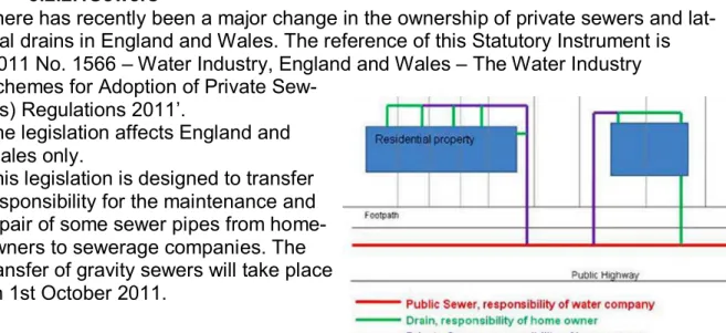
3.2.2.1Sewers
There has recently been a major change in the ownership of private sewers and lat-eral drains in England and Wales. The reference of this Statutory Instrument is ‘2011 No. 1566 – Water Industry, England and Wales – The Water Industry Schemes for Adoption of Private
Sew-ers) Regulations 2011’.
The legislation affects England and Wales only.
This legislation is designed to transfer responsibility for the maintenance and repair of some sewer pipes from home-owners to sewerage companies. The transfer of gravity sewers will take place on 1st October 2011.
Diagram showing the responsibilities prior to the transfer on 1st October 2011.
Section 3 - Site Survey
3.2.3 Ground conditions
The types of foundation are always dependent on local ground conditions and the Surveyor should always determine the details of the existing property founda-tions.
In some instances specialist foundations may be required for the conservatory, e.g. due to reclaimed land, poor ground conditions, or the presence of trees or rock in the area, Building control or a Civil/Structural engineer may need to be con-tacted.
Diagram showing new responsibilities after 1st October 2011 in relation to gravity sewers only
National guidelines relating to building over these newly transferred sewers are cur-rently being negotiated between the sewerage undertakers (mainly water compa-nies in the UK represented by Water UK) and DEFRA and DCLG. The GGF is also involved in these discussions specifically to represent the interests of conservatory installers.
Until these guidelines have been agreed, all installers should confirm with the local sewerage undertaker if there are any agreements/permissions required before com-mencing works. It should be noted that if agreements/permissions are required, there will be a cost associated with this and this will vary according to who the sew-erage undertaker is.
This section of the guide will be updated to reflect final arrangements relating to building over or near sewers once agreement has been reached.
3.3 Ground assessment
· Careful attention to the assessment of the ground conditions is essential, as this will influence the type and depth of foundations for the conservatory.
· The foundations of the adjacent dwelling should be established as soon as practical as this will be a guide as to the type suitable for the conservatory.
Section 3 - Site Survey
· It is recommended that, where practical, an inspection pit is dug to expose the existing house foundations to enable a full risk assessment for the new conserva-tory foundations to be carried out.
· Confirm with the clients and if possible with neighbours, whether any trees or large shrubs have been removed within the preceding 12 months, including those in neighbouring gardens?
· Due care must be taken when considering building near trees, guidance con-tained in NHBC Guide, section 4.2 - Foundations - ‘Building near trees’ should be consulted.
· Are any trees protected by a Tree Preservation Order (TPO), which may be af-fected by the position of the conservatory?
· The ground may be subject to soil shrinkage or heave, this is caused by the natu-ral seasonal changes in water content of the soil. This usually occurs in clay soils and will be affected by the presence or removal of trees. These conditions should be catered for in the foundation design.
· Is there an existing patio area to take up? Will this material be re-used or will this need to be removed from site?
· On sloping sites, does ground need to be excavated or in-filled?
· What are the implications of building the conservatory foundations in regard to Health and Safety legislation.
3.3.1 Difficult ground or unusual existing foundations
Where the following conditions are found or known to exist, specialist advice should be sought from a qualified structural, civil engineer or a specialist geotechnical engineer:
· Is the house or will the proposed conservatory be built on made-up ground?
· Where the existing property is known to have non-standard foundations, e.g. Raft or Pile foundation
· Has the house previously suffered from subsidence?
· Is the house in an area subject to mining subsidence?
· Is the house in an area prone to landslip?
3.3.2 Drainage
Identify and plot any existing underground drainage and ser-vices. Lifting of manhole covers is essential for the identifica-tion; direction and depth of existing drainage runs and a visual check on neighbouring gardens may also prove to be helpful.
Section 3 - Site Survey
3.3.3 Radon, Methane and Carbon Dioxide
In addition to assessing the structural ground conditions, the surveyor should establish whether there are any local requirements for Radon or Methane gas preventative measures. Check whether built on ‘brown field’ site, this will often be an indication of possible land-fill and therefore the risk of methane.
The construction of the conservatory must not compromise any existing ground gas protection system installed in the dwelling
Radon risk areas in England and Wales
Guidance on protection against Radon is contained in the BRE publications: Radon: guidance on protective measures for new dwellings and BR 414: Protective measures for housing on gas-contaminated land. This publication also includes maps that indicate areas where radon protection is required.
Section 3 - Site Survey
Radon risk areas in Scotland
Section 3 - Site Survey
3.4 Measurement survey
This will entail neat line drawings and include the following:
· Details of the particular elevations of the prop-erty against which the conservatory is to be situated in both plan and elevation.
· Careful positioning of all existing windows, ser-vice pipes, drains and other instructions must be highlighted, including heat producing appli-ances. Further information can be found within clause 3.4.1
· Any special brickwork or corbelling/render stop details must be clearly identified, as these will indicate whether special packers are re-quired prior to the framework being fitted. The dimensions between each feature should be clearly indicated and the outline of the pro-posed conservatory indicated. It is useful for the site measurement survey to be backed up with adequate photographs.
· After checking the overall height of the pro-posed conservatory and ensuring that the roof and the flashing required will fit underneath existing window or the eaves of the property.
· Check whether the house wall is vertically plumb.
· Check the position of all rainwater pipes, ca-bles, airbricks, extractors and soil vent pipes.
The surveyor should make consideration to the design and specification of the flashing detail at the abutment of the conservatory roof and the existing house wall.
· The general condition and type of the existing wall should also be observed to assess whether the installation of cavity trays or flashings will be advisable, tak-ing into account local construction methods. If cavity trays are generally installed in an area when extensions are added to existing buildings, it is likely that it is a high weather exposure area and moisture penetration is likely if they are not in-stalled. Under these circumstances it is also important to bare in mind other junc-tions with the original building to ensure suitable measures are taken to avoid moisture ingress.
Section 3 - Site Survey
· If the conservatory design have roofs thatin-corporate box gutters, due regard must be given to their structural support, rainwater ca-pacity and accessibility for maintenance. The surveyor should ensure there is adequate pro-vision for discharge outlets from all gutters and box gutters.
· If moving a projecting obstruction (e.g. Soil and Vent Pipe) is not feasible, then it will be neces-sary to cater for the obstruction when designing the conservatory. Soil vent pipe flashing kits are readily available and these are designed to fit around the stack and seal to the roofline.
3.4.1 Check for existing walls being plumb and square
If the house wall leans forward then all setting out dimen-sions for the projection of the base must be taken from the vertical plumb line as demonstrated in the diagram ‘A’. If the house wall leans backward, this indicates that some form of extension to the ridge will be needed as indicated in diagram ‘B’. Whether the wall leans inwards or out-wards, packers to the side frames and roof will be required as indicated in diagrams ‘A’ and ‘B’.
However, any leaning wall should be further investigated to ensure that it is structurally stable and able to support the con-servatory and withstand wind and snow loads imposed on it by the conservatory.
It may be advisable to specify an in-fill/packer component to be fixed to the rear of the side frames, which abut the house wall. This will give the facility, if required, to secure a rainwater pipe (RWP) at this position to prevent it interfer-ing with the window frame.
Adjacent walls and corner details should also be checked for squareness to the host wall, e.g. a garage wall opposite the house being abutted by a box gutter.
Tip
Check the position of any box gutter supports for conflict with existing
Section 3 - Site Survey
3.5 Other design specification requirements
The surveyor should check the aspect and orientation of the conservatory and the relative position of any surrounding buildings and other tall objects (trees etc.), that may cast shad-ows on the conservatory. It is vitally important at this stage to ensure adequate provision for high level ventilation is provided for cooling in the summer months. Dependant on the antici-pated levels of Solar heat gain, methods of reducing this through the use of Solar control glazing should be considered along with the installation of automatic roof windows with rain sensors and the installation of blinds.
The conservatory may have three aspects, i.e. three elevations, consider which elevation is dominant, this will assist with an assessment for any solar control measures necessary.
3.6 Site and build risk assessment
It would be prudent at this early stage, to complete a detailed risk assessment of both the site and the build process to determine potential areas of risk to enable corrective action to be taken in good time. This will help to avoid site delays or failure of the in-stalled conservatory in the future.
3.7 Reference information Section 3
Gas Safe technical services and BS 5440.
BRE publications: Radon: guidance on protective measures for new dwellings and BR 414: Pro-tective measures for housing on gas-contaminated land.
Building regulations Approved Documents A, B, C, J
BRE Digest 240 Low-rise buildings on shrinkable clay soils part 1
BRE Digest 241 Low-rise buildings on shrinkable clay soils part 2
BRE Digest 298 Low rise building foundations.
NHBC Standards Chapter 4.2 Building near trees.
The surveyor must provide relevant site data to allow the designer to analyse the con-servatory structure for wind and snow loadings, e.g. altitude, location, exposure, topog-raphy and other relevant features. If the surveyor is unsure then contact a suitably
Section 3 - Site Survey
Section 3 - Site Survey
Section 3 - Site Survey
Section 4 - Base Design and Construction
Section Contents
4.1 Loading
4.2 Ground movement
4.3 Site preparation and resistance to moisture 4.4 Special circumstances
4.5 Underground drainage and rainwater disposal 4.6 Substructure design
4.7 Site control 4.8 Setting out on site 4.9 Drainage
4.10 Soil stacks
4.11 Brickwork to DPC
4.12 Masonry wall construction 4.13 Damp proof measures 4.14 Effect of a sloping site 4.15 Signing off base works 4.16 Reference information
The foundations of the conservatory shall meet the following requirements.
Note: Although a conservatory may be exempt from Building Regulations, it is a requirement to ensure all works are carried out to a standard to secure a reasonable standard of health and safety for persons in or about the buildings.
Reference should also be made to BS8103 -1: 1995 and Approved Document A
4.1 Loading – Building Regulation A1
A1. (1) The building shall be constructed so that the combined dead, imposed
and wind loads are sustained and transmitted to the ground: a) Safely; and
b) Without causing such deflection or deformation any part of the building, or such movements of the ground, as will impair the stability of any part of another building.
(2) In assessing whether a building complies with sub paragraph (1) regard
shall be had to the imposed and wind loads to which it is likely to be subjected in the ordinary course of use for the purpose for which it is intended.
Section 4 - Base Design and Construction
4.2 Ground movement – Building Regulation A2
A2. The building shall be constructed so that the ground movement caused by: a) Swelling, shrinkage or freezing of the sub-soil; or
b) Land-slip or subsidence (other than subsidence arising from shrink-age, insofar as the risk can be reasonably foreseen), will not impair the stability of the building.
4.3 Site preparation and resistance to moisture
The ground to be covered by the building shall be:
· Free from vegetation.
· Dangerous and offensive substances:
· Precautions shall be taken to avoid danger to health and safety caused by substances and gases found on or in the ground to be covered by the build-ing.
Resistance to weather and ground moisture:
· The floor of the building shall resist the passage of moisture to the inside of the building. A suitable DPM, which joins the brickwork DPC, should be installed to ensure adequate resistance to ground moisture ingress through the floor slab.
4.4 Special circumstances
Where the following conditions are found or known to exist:
· Made up ground.
· Weaker type of soil with low bearing capacity to greater than normal depths.
· Wide variation in sub-soil within local area.
· Where the existing property is known to have non-standard foundations.
· Where excessive ground shrinkage or heave will occur.
· Where the house is built on non-standard foundations.
A more sophisticated foundation detail may be required. These will require the services of a Structural/Civil Engineer. Such alternative foundations are:
· Reinforced raft foundation
· Piled foundation
Note: If raft or piled foundations are to be used and the original house foundations are of a different type or if both the house and new foundations are raft, advice should be taken to en-sure differential movement does not occur or is accounted for in the design.
Section 4 - Base Design and Construction
4.5 Underground drainage and rainwater disposal
As most conservatories are sited either at the side or the rear of the property, then it is possible that the foundations will interfere with some form of existing underground drainage.
Every care must be taken during excavation to prevent damage to underground drainage, which may or may not have been high-lighted on the survey document.
If the drainage cannot be diverted around the outside perimeter of the conservatory, then adequate means of bridging the foundation over the drain line and encasement of the drain must be under-taken prior to the foundations being formed.
The exact requirements for protection to existing drains will be determined on site and will be dependent on their type and depth.
New rainwater drains should be laid to fall and connect into an existing drainage system where possible. Access for maintenance should always be considered and provided as nec-essary. Where connection to an existing drain is not possible, then suitable discharge to local watercourse or soak away should be considered.
The condition of the existing manholes should be checked and any remedial/strengthening building work carried out, if it is not being relocated.
4.6 Substructure design
The majority of domestic conservatory installations can be constructed using conventional concrete foundations (see diagram in 4.6.1). However, each company will have their own preferred method based, at least in part, on knowledge of local ground conditions and local working practices.
Tip
Check whether the existing
drain-age system is a combined foul and
rainwater system
Existing manholes within the conservatory floor area may be raised and fitted with a double sealed cover, with provision for floor finish. It must be confirmed with the local water authority that this is allowed, they may insist on the manhole
Section 4 - Base Design and Construction
4.6.1 General
From the survey information and site measurement documents, it will now be possible to de-sign the actual base for the conservatory. The critical points requiring detailed attention are as follows :
· Setting Out Point (SOP). This gives a datum point from the site measure-ment survey as to where the conservatory is to be positioned on the prop-erty. It will usually be de-noted as an existing fea-ture (opening reveal, cor-ner of building etc.) or a dimension from some critical point
· The relative floor level of the conservatory in rela-tion to the house floor level.
· The relative DPC level of
the conservatory in relation to the DPC level of the property.
· d) Ensure consideration is given to level of exposure of the existing building cor-ners where the conservatory abuts, to ensure moisture penetration through brick-work does not occur. Conservatory abutments should be set in from corners sub-ject to severe weather exposure.
· e) The general ground level in relation to the house DPC level. The DPC level of the conservatory should be at least 150mm above the external ground level. Where this cannot be achieved, it will be necessary to either lower the external ground level around the outside of the conservatory or alternatively build either, a gravel filled trench 150mm wide by 150mm deep or lay a concrete gully around the perimeter wall of the conservatory to avoid damp penetration above DPC level.
· f) The general lie of the external ground level and whether it falls away from or towards the conservatory.
· g) Sloping sites can produce several possible problems. For instance, if the ground level is much lower than the proposed conservatory level, then it may not be feasible to install a ground supported floor slab in the conservatory due to the amount of in-fill required. If a suspended floor is to be constructed, this will
Section 4 - Base Design and Construction
need to build a landing/platform (generally the width of the door(s)) and with a projection equivalent to the swing of the door plus a minimum of 400mm. This will allow for the customer to safely step out before walking down the steps. Steps will be required wherever the floor level of the conservatory is more than 150mm higher than the external ground level. Approximately one step is required for every 150mm increment in height. Should the steps be higher than 600mm it will be necessary to fit a hand rail/balustrade to each side of the set of steps, and this should always conform to building regulations (Approved Document K {ADK}). Depending on which way the site is sloping, it may result in additional height to the conservatory wall below floor level.
If the external land is falling towards the conservatory then serious excavation will be neces-sary plus possibly the building of a retaining wall to give support to the remaining bank of high-level ground.
4.6.2 Foundations of plain concrete
From section 2E Approved Document A, (ADA) Conditions relating to the ground: 2E1 There should not be:
a) non-engineered fill (as described in BRE Digest 427) or wide variation in ground conditions within the loaded area; nor
b) weaker or more compressible ground at such a depth below foundation as could impair the stability of the structure
4.6.3 Strip foundations
Unless there is evidence of poor subsoil conditions on the site, a traditional concrete strip footing or trench fill foundation placed under the walls of the conservatory will normally suf-fice. The new foundation should be constructed in such a way that it does not undermine the foundations of the main building.
Section 4 - Base Design and Construction
4.6.4 Minimum width, thickness and depth of strip foundations
The minimum width of foundation should be designed to suit the wall construction, the condi-tions of the ground they are bearing on and the loads imposed on the ground by the conser-vatory.
The imposed load can be simply determined by reference to Table 4 in BS 8103-1:1995. Extracts from Table 4 – Wall load categories for floors to 4.5 m and roof to 9 m
Section 4 - Base Design and Construction
Extracts from Table 7 – Identification of ground material and minimum foundation widths for wall load categories
The minimum depth of foundations should be determined as the greatest of the following:
· A depth to the bearing stratum
· In clays subject to seasonal moisture movement, a depth not less than 1.0 metre.
Rock or soil
Simple field test
Mimimum foundation width in mm, for load category (kN per metre run)
Type Condition A (20) B (30) C (40) D (50)
Rock Hard
Requires at least a pneumatic or other mechanically operated
pick for excavation
Equal to width of wall
Gravel
Compact
Requires pick for excavation. Wooden peg
50mm square hard to drive in more than
150mm. 250 300 400 500 Sand Clay Stiff Cannot be moulded in the fingers. Requires pick or pneumatically operated spade for
excavation
250 300 400 500 Sandy clay
Clay
Firm
Can be moulded with substantial pressure with
the fingers and excavated with a spade
300 350 450 600 Sandy clay
Sand
Loose
Dry lumps may have slight cohesion but easily breaks up in fingers. Readily excavated with spade. 50mm peg can be easily
driven in. 400 600 Refer to specialist for advice and design Silty sand Clayey sand Silt Soft
Easily moulded in the fingers and readily
excavated 450 650 Clay
Sandy clay Silty clay
Silt
Very Soft Exudes between fingers when squeezed in fist 600 850 Clay
Sandy clay Silty clay
Peat ----
Refer to specialist for advice and design Made Ground ----
NOTE: In no case should the foundation width be less than the width of the wall nor should the wall over-sail the foundation.
Section 4 - Base Design and Construction
· In sands, chalk and other frost-susceptible soils, a depth below the zone of frostaction, which may normally be taken as a minimum of 450mm. In upland areas and other areas known to be subject to long periods of frost and increase in depth may be advisable.
· Where the foundation trench is adjacent to a service trench (e.g. water, sewage etc), a 45 degree line taken downwards from the bottom corner of the trench near-est the service trench, must pass below the excavation depth of the corner of the service trench nearest the new foundation.
The depth of foundations must also take due consideration of the influence of nearby vegeta-tion and trees. Specialist advice on the type and depth of foundavegeta-tions to be located near trees and bushes is given in the NHBC Standards Chapter 4.2 –
Building near trees.
Where a strip footing is being used, the minimum depth of concrete must be the greater of either 150mm or ½(difference between total foundation width and the total wall thickness). Where trench fill concrete foundations are being used, the concrete should not finish less than 150mm below finished external ground level.
Where it is necessary to step the foundations, the following must be adhered to:
· Strip footings must be overlapped by either the thickness of the concrete, twice the step height or 300mm, whichever is the greatest.
· Trench fill foundations must be overlapped by
either twice the step or 1 metre, whichever is the greatest.
In general, the wall should be positioned such that the centre line of the wall is in line with the centre line of the foundation. However, in certain circumstances this may not be possi-ble, e.g. when building on a boundary and it is not possible to excavate over the boundary. In such cases the wall can be offset from the centre line but the centre line of the wall must be within the middle 1/3 of the width of the foundation.
Where the wall has projections such as piers, the foundation should be excavated such that the distance from the face of masonry to the edge of concrete foundation is main-tained.
In some situations, due to the type of soil on site, it may not be possible to use simple concrete foundations. In these cir-cumstances it will be necessary to consider the use of more specialist foundations such as reinforced raft or piled founda-tions.
4.6.5 Raft Foundations
Tip
Construction on brown-field sites normally re-quires the use of raft or
Section 4 - Base Design and Construction
area than strip foundations and has the advantage of reducing differential settlements over the site. However, there is potential for there to be differential movement between a new raft foundation and the original house foundation, in particular if the house foundation is also of raft construction.
Normally the raft foundation consists of a reinforced concrete slab.
Specialist advice should be sought regarding the design and suitability of this type of foundation.
4.6.6 Pile foundations
Pile foundations are used to carry and transfer the load of the structure in ground conditions such as shrinkable clays, brown-field sites, infill sites and or waste tips to a solid load bearing strata. They are a substitute where conventional foundations would need to be so deep that they would be un-economical. The main types of materials used for piles are Steel and Concrete, normally shaped as a tube. These tubes are driven, drilled or jacked into the ground, often filled with
con-Section 4 - Base Design and Construction
4.6.7 Wall design
There are two distinct different styles of conservatory:
· A full height panel conservatory, where the frames sit on a perimeter plinth of brickwork, at DPC level.
· A dwarf cavity wall conservatory, where the frames sit on a wall, which is usually between 450mm/600mm high above internal floor level. This is probably the most popular design.
A conservatory with dwarf wall construction and especially where a reasonable matching brick is available will always create an impression of the conservatory being part of the origi-nal house.
The height of the dwarf wall needs to be carefully considered. This should be expressed as a height above the internal floor level of the conservatory or the conservatory DPC.
The most popular height being 450mm or 600mm.
All external walling, whether dwarf or full height, should give protection against rain penetra-tion. Solid walls should be of a sufficient thickness to resist rain, cavity walls may be used or the wall protected by an impervious or weather-resisting cladding.
Consideration should be given to providing continuity between the DPC/DPM of the host house and the conservatory to form an impermeable barrier.
Check the coursing of the house brickwork to ensure the conservatory coursing will match the original house if pos-sible. On modern properties the coursing is usually in incre-ments of 75mm. On older properties (pre 1970’s), imperial size bricks may have been used, these may be difficult or impossible to obtain and the modern metric equivalent may not course in.
The Surveyor should note the ‘under built’ height to avoid oversight of these issues.
Section 4 - Base Design and Construction
4.6.8 Thermal performance of walls
Although many conservatories are exempt from the thermal require-ments of Approved Document Part L, it is seen as good practice, wher-ever practical, to meet the thermal requirements for walls as stated in AD L. For walls this is given in section 2.6.4.
Any conservatory that is not exempt from building regulations will need to fully comply to the requirements of AD L.
Other methods of construction may achieve compliance, advice and guid-ance can be obtained from material suppliers on the appropriate wall con-struction and specification to meet the target U values.
However it should be pointed out to the customer that a cavity dwarf wall will reduce the internal floor area of the conservatory (owing to the thick-ness of the wall).
This may be a consideration if the overall external size of the conservatory is restricted due to the space available on site.
4.6.9 Door positions
On a faceted conservatory, many customers will request the position of the doors to be in one of the front bay facets. This is not always practical and sensible owing to the following points:
· Size of front bay facets.
· Clear access through the conservatory.
· Optimum use of space within the conservatory will affect where the door should be positioned.
· Obstructions such as soil and vent pipes or gas vents may need to be avoided.
· Where the door jamb is close to an external brickwork corner of the conserva-tory, there may be issues sourcing or fabricating the correct shaped bricks.
· If the door, in particular sliding or bi-fold doors, are positioned in the middle wall of a three sided conservatory, consideration needs to be given to the effect this will have on the structural stability of the conservatory. Research has shown that when doors are positioned in this elevation or in one of the facets of a conserva-tory, the ability of the conservatory to resist deformation due to wind loading is greatly reduced. If doors are to be located in these areas, consideration to the in-clusion of wind-post or structural goal-posts must be considered.
4.6.10 Floor design
The conservatory floor will generally be at the same level as the dwelling, safe access should be considered if steps are required to the adjoining house. The floor design should pay atten-tion to any insulaatten-tion requirements, whether under floor heating is specified or if channels are required for central heating pipe work.
Section 4 - Base Design and Construction
4.6.11 Thermal performance of floors
As with walls, exempt conservatories do not need to meet a speci-fied floor U-value but the new floor should not be worse than the floor in the existing house and it is good practice to design the floor to the current requirements of AD L. The current requirements is given in section 2.6.4.
Advice on methods A ground bearing solid floor would gener-ally be specified when the distance between external ground level and internal floor level is not greater than 600mm. This is because of the amount of “in-fill” required to build up the
floor area within the conservatory. The procedure for the floor construction should be as follows:
a) All vegetation and topsoil should be removed from the ground area within the conserva-tory wall.
b) The over-site concrete slab should be laid level to accept the final finish, this can either be boarding on insulation or a sand and cement screed to accept a tiled finish. The concrete slab should be at least 100mm in thickness and laid over insulation that should rest on a Damp-Proof Membrane of 1200 gauge thickness. The DPM should be laid over 50mm of sand blind-ing on at least 150mm of well compacted hardcore.
c) The edges of the DPM should be dressed vertically around the perimeter of the pro-posed floor slab and taken up to meet any existing DPC in the existing house wall. The inner leaf of the rising perimeter wall to the conservatory should be fitted with a wide DPC over-lapping the inner face of the wall by 100mm. This overlap of the DPC should be turned down and lapped over the edge of the DPM before the concrete floor is cast. It is important that any existing airbricks within the house wall are ducted out under the new floor slab to the perimeter of the conservatory walls, or re-sited adjacent to the new conservatory to main-tain under floor ventilation to the property.
4.6.12 Suspended floors
Where site conditions of over 600mm exist between ground level and conservatory floor level or the ground does not have sufficient load bearing capacity to support a ground bear-ing concrete slab, it may be advantageous to install a suspended floor of timber or reinforced concrete construction. This will have under floor ventilation if the floor is of timber construc-tion and may have ventilaconstruc-tion included if the existing house is ventilated below floor level. If the existing house has under- floor ventilation (air-bricks below DPC), provision must be made to extend these to the outside of the conservatory.
Reinforced concrete suspended floors, pre-cast concrete beam and block suspended floors and suspended timber floors should be supported on the external masonry walls and where necessary, intermediate walls which incorporate adequate provision for the free flow of un-der floor ventilation.
Section 4 - Base Design and Construction
4.6.13 Disabled access
See typical requirements for disabled access below:
NB. Disabled Access Requirements.
Accessibility must not be made any worse than existing. The provision of Disabled access should be considered, taking note of the requirements of the owner within the site survey.