Appendix 9
P Elkington BE(Civil) MIE Aust RPEQ Associate
CP Johnson BEng(Civil) RPEQ
______________________________________________________________________
Celebrating over 40 years in Geotechnics
Brisbane, Level 2 19 Finchley Street, Milton QLD, PO Box 317, Paddington, QLD, 4064, Australia Ph +617 3369 6000, Fax +617 3369 6660, [email protected]
Gold Coast, Unit 8, 140 Millaroo Drive, Helensvale, QLD, PO Box 3429, Helensvale, QLD 4212, Australia Ph +617 5500 0465, Fax +617 5500 0462, [email protected]
Incorporating Soil & Water Laboratories Milton Office
Job No: 214-11895
Ref: 2-11895, 2014-10-14, LR VER 2 Author: Noel Perkins
10 December 2014
Capworks Management QLD Pty Ltd Email: [email protected] ATTENTION: MR TERRY O’SULLIVAN Dear Sir,
RE: GEOTECHNICAL INVESTIGATION
PROPOSED TRADE SKILLS CENTRES
NERANG STATE HIGH SCHOOL, NERANG-GILSTON ROAD, NERANG
1.0 INTRODUCTION
1.1 General
This report presents the results of the geotechnical investigation carried out by Soil Surveys Engineering Pty Limited at the above site.
1.2 Proposed Development
It is understood that the proposed development will comprise the construction of a new single storey trade skills centre of tilt-panel type construction at the above site. An extension of an existing driveway to allow vehicle access to the new building is also to be constructed. We understand that cuts up to 3.5m may be undertaken.
1.3 Scope of Works
The objective of this study would be to identify materials and material properties to enable geotechnical assessment of the following:-
Earthworks recommendations - traffickability
- subgrade preparation
- compaction standards
- suitability of cut for use as fill
- safe batter angles for cuts
Foundation recommendations - recommended foundation type
- bearing capacity - site classification
- predicted ground surface movement
Slope Stability Assessment
Retaining wall design parameters
Pavement recommendations
Construction recommendations (where applicable)
Site management recommendations
2.0 SITE
INVESTIGATION
2.1 Field Investigation
Subsurface conditions were investigated by drilling and sampling four boreholes, to refusal depths of 0.8m to 1.3m, using a 4WD mounted Jacro105 drilling rig.
The soil classification descriptions and field tests were carried out in general accordance with the following Australian Standards:-
AS 1726-1993 Geotechnical Site Investigations
AS 1289 Methods of Testing Soils for Engineering Purposes
Details of the investigation method, borehole records, dynamic cone penetrometer results and a site plan showing the location of the boreholes are attached.
The classification of soils in the field is subjective, based on the experience and judgement of the geotechnical driller and some variations in the soil description, from the actual material type may occur. In order to reduce any inconsistencies which may have occurred, the field descriptions have been corrected, where appropriate, to reflect the available laboratory test results.
2.2 Site Description
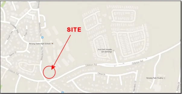
The site is located at Nerang State High School Campus on Nerang-Gilston Road, Nerang, South East Queensland (refer Figure 1).
Access to the site is off Nerang-Gilston Road.
The site has been described as moderately/well drained with no seepage noted. The area is poorly grassed with a thick covering of small to medium sized trees.
The site slopes to the east with a fall of 2.0m to 3.0m over the site. An existing rock cut is located to the east of the proposed building. This cut is approximately 2.0m high and cut at approximately 40˚- 50˚ above the horizontal.
FIGURE 1 – SITE LOCATION
PLATE 1 – EXISTING ROCK CUT ON EASTERN SIDE OF SITE
2.3 Subsurface Profile
The subsurface profile encountered consisted of:-
Residual Soil - this was encountered in all the boreholes. It was described as medium dense Silty Gravelly SAND (SM) and Gravelly SAND (SP) or hard Sandy CLAY (CH) of high plasticity, brown, red and grey.
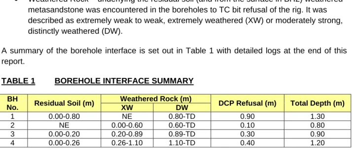
Weathered Rock – underlying the residual soil (and from the surface in BH2) weathered
metasandstone was encountered in the boreholes to TC bit refusal of the rig. It was described as extremely weak to weak, extremely weathered (XW) or moderately strong, distinctly weathered (DW).
A summary of the borehole interface is set out in Table 1 with detailed logs at the end of this report.
TABLE 1 BOREHOLE INTERFACE SUMMARY BH
No. Residual Soil (m)
Weathered Rock (m)
DCP Refusal (m) Total Depth (m)
XW DW
1 0.00-0.80 NE 0.80-TD 0.90 1.30
2 NE 0.00-0.60 0.60-TD 0.10 0.80
3 0.00-0.20 0.20-0.89 0.89-TD 0.30 0.90
4 0.00-0.26 0.26-1.10 1.10-TD 0.40 1.20
Groundwater was not intersected in any of the boreholes at the time of investigation.
2.4 Laboratory Testing
Laboratory testing was carried out on selected samples retrieved from the site investigation program and was directed towards assessing the reactivity and subgrade parameters of the subsurface material.
Laboratory testing included:-
California Bearing Ratio, to assess the subgrade parameters for pavement design (BH1 at 0.2m, CBR = 11%)
Shrink Swell Index test to assess the reactivity of the clay soils (BH1 at 0.4m, Iss = 2.0%)
The laboratory test certificates are attached.
3.0 ENGINEERING
ASSESSMENT
3.1 Traffickability and Site Preparation
At the time of the field investigation, traffickability was considered to be moderate to good however the site was heavily treed.
Problems may arise from disturbance of the upper level soil fabric with removal of vegetation, existing structures and services. Depressions could be formed resulting in water traps with potential softening of adjacent and underlying soils.
Nevertheless, the contractor should fully inform himself of the ground conditions on site prior to commencement of earthworks. This requirement should be explicit in any earthworks specifications or contract.
This particularly applies to the sandy residual soils encountered several of the boreholes. Silty sand material when saturated is likely to cause traffickability problems and is generally not suitable for structural fill.
Working Platforms For Tracked Plant and Heavy Construction Vehicles
The scope of Soil Surveys Engineering’s study DOES NOT include the design of a working platform for heavy construction vehicles or heavy tracked plant.
Detailed design of a working platform should be carried out considering the operation of actual machinery proposed to be used. This is particularly important when considering the use of heavy piling rigs and heavy cranes - the piling/crane contractor should be consulted regarding their requirements.
3.2 Civil Works
Earthworks - General
The amount of earthworks onsite has not been confirmed however it is understood that cuts of up to 3.5m may be undertaken.
Earthwork procedures should be carried out in a responsible manner in accordance with AS 3798-2007 'Guidelines on Earthworks for Commercial and Residential Developments'. It is recommended that the earthworks contractor make himself familiar with site conditions.
Earthwork procedures should include the following:-
Clearing, stripping and grubbing should be carried out in areas subject to earthworks. Also all soils containing organic matter should be stripped from the construction area. This material is not considered suitable for use as structural fill.
Depressions formed by the removal of vegetation, underground elements etc. should have all disturbed weakened soil cleaned out and be backfilled with compacted select material.
In areas where fill is to be placed, the existing ground surface should be proof rolled (if appropriate) using a vehicle with a tare of at least 3 tonnes. Areas demonstrating excessive movement should be treated (dried and recompacted) or removed and
replaced with compacted fill. In areas of cut, proof rolling may be deferred until after the cut operation.
The insitu soils, where free of organic and deleterious material, may be used for structural fill provided the moisture content of the soils on placement approximates the optimum moisture content required for compaction. This may require conditioning to bring the soils to optimum. However, it should be noted that silty/clayey sands and plastic clay soils could be expected to present difficulties in handling, placement and compaction if the appropriate moisture content could not be achieved, particularly if the soils were overly moist. Soils selected from site for reuse should be selected on the basis of their likely effect on the site’s reactivity.
Imported select fill material, if required, should be a good quality select fill material with a soaked CBR >10% and a maximum aggregate size of 75mm. If material with a CBR of <10% is to be considered due to local supply issues, it is recommended that remoulded Iss testing be undertaken with a maximum recommended value equal to the maximum Iss test result for natural site material. The level of supervision of the fill would also need to be considered.
Fill placed in the areas of building should be compacted in layers (approximately 250mm
loose thickness) to a density not less than 98% of maximum dry density in accordance with AS 1289 5.1.1 (Standard Compaction).
Field density testing should be carried out in each fill lift placed to check the standard of compaction achieved and the placement moisture content. The frequency and extent of testing should be as per guidelines in AS.3798-2007, Section 8.0.
Most soils encountered on site (to borehole depths) should be within the excavation limits of a small dozer (eg. Cat D4 or similar) in bulk earthworks and a medium sized backhoe (eg. Case 580 or similar) in trench excavations.
Weathered rock encountered in the boreholes will require the use of medium to large sized excavators in the more weathered horizons with the possible need, single tyne ripping and rock breakers in the less weathered layers particularly below the rigs TC bit limits
Batters
Maximum batter angles for different material types are outlined in Table 1 for unsurcharged cut and fill batters less than 3.5m high. Where surcharges (eg. footings, live loads, etc.) are located within H (height of batter) of the top of the batter, then some reduction in design angle will occur. Steeper batters are possible with suitable surface protection such as stone pitching, etc. or by use of retaining structures (temporary and permanent). Fill batter slopes are dependent on suitable compaction being achieved.
TABLE 2 MAXIMUM BATTER ANGLES (Slopes less than 3.5m high)
Material Short Term Long Term
Compacted Fill 45 degrees 26 degrees
Clay Soils 45 degrees 26 degrees(1)
Weathered Rock 60 degrees 45 degrees
Notes:
Where cut off drains are employed some increase in slope angle could be considered. 1)
Subject to inspection by experienced geotechnical engineer/engineering geologist. 2)
It is essential that permanent batters be suitably protected from erosion and scour by appropriate drainage and the establishment of ground cover and shrubs, etc. Imperative to the stability of the batters is good drainage to prevent potential fretting and/or slumping. It is therefore recommended that measures be taken to minimise the flow of water over batters. Drying out of the reactive clays in the batters would result in surface cracks which have the potential to become saturated and fret during rainfall periods. This could result in eventual slumping and failure of these sections of the batter faces.
Consideration should therefore be given to protecting the final batter faces by cutting the slopes to a maintainable profile and providing a good surface covering, eg. vegetation, grass.
3.3 Site Classification
A site classification, in accordance with AS 2870 'Residential Slabs and Footings' (it is recommended that the reader satisfy themselves that the use of AS 2870 is applicable for the proposed design) has been carried out with the following assumptions:-
Subsurface profile
Residual soils (predominantly sands but clay in BH1) over shallow (surface to depth of 0.8m) weathered rock.
Proposed earthworks
Possible cuts of up to 3.5m
Possible filling of up to 3.5m Soil Moisture Model
A zone of moisture variation of 1.5m
A crack zone of 0.75m
pF = 1.2
Based on the subsurface profile encountered in the boreholes, a ground surface movement (ys) of <20mm (maximum) has been calculated for the existing site surface (i.e. no cut or fill). Therefore the site may be designated Class ‘S’ slightly reactive site.
The above classification is based on the existing ground profile. If any filling or cuts in excess of 0.5m occur on the site, the ys value will change and therefore the site classification may also change.
It should also be noted that the methodology adopted for determination of the site classification assumes the structure has performance requirements similar to domestic type construction. Effect of Cuts on the Site Classification
Based on the borehole intersections where cuts of greater than 0.8m occur, the exposed subgrade will be weathered and therefore the site classification will be designed as 'A' (Rock site).
Effect of Filling on the Site Classification
Where filling of excess of 0.5m occurs, the site classification will depend upon the type of control and certification of the fill.
Where filling is not engineer certified as being suitable for the installation of footings (e.g. an allowable bearing capacity is provided), the site classification shall be designated as a 'P' (problem) site.
Where filling is engineer certified as being suitable for the installation of footings and slab (e.g. an allowable bearing capacity is provided), and the fill used is site fill and behaves in a similar manner as fill as it would insitu, then the site classification is likely to be P/'S' (problem site reclassified as a slightly reactive site).
Where filling is engineer certified as being suitable for the installation of footings and slab (e.g. an allowable bearing capacity is provided), and the fill used is imported then the site classification shall be 'P' (problem site) reclassified depending upon the characteristics of the imported fill which would need to be checked.
Effect of Trees
AS 2870-2011 includes a non-mandatory section of how to address the effect of trees on the structure. This is covered in Appendix H of the Standard. Using some site parameters with respect to trees a yt value is calculated, this value being the potential surface movement due to the tree induced suction change in addition to the normal designed suction change.
As trees have been noted on this site, an assessment of the yt value has been made. This has
been made on the basis of the following:-
Design Height of a single tree = 4
Design height of a group of trees = 4
Distance of tree/s to the building = 0
Location of the trees used in the design is over the site of the proposed development Based on the above values a yt value of 30mm has been calculated.
The recommendations provided by the code on how to apply this value are outline in Appendix H4(e)(ii) to H4(e)(v).
3.4 Foundations
General
The recommended foundation option will depend upon the proposed earthworks on the site eg.:-
Should cuts in excess of say 1.0m occur over the site it is likely that the exposed
subgrade will consist of weathered rock and in which case the use of high level footings foundation would be recommended.
Should the site of the building be filled (provided drawing suggests an elevation difference of some 3.5m across the building footprint then the use of deep foundations founding into the weathered rock and a fully suspended or structurally separate ground slab (depends on level of earthworks supervision) may be required.
High Level Footings
Where high level footings are adopted, our recommendation is that all footings, be founded at least 400mm below platform level or 200mm into weathered rock.
Footings when founded in the weathered rock may be dimensioned for a minimum allowable bearing pressure of 500kPa.
Where necessary, footings deeper than 400mm may be made up with mass concrete poured to the underside of the footings, or alternatively, footings may be constructed over mass concrete filled, backhoe excavated pedestals.
Deep Foundations
General
Bored piers could be considered.
It is recommended that the deep foundations used on this project be designed in accordance with AS 2159-2009 Piling - Design and installation. This code uses the limit state design method. In the limit state design method the following must be taken into account:-
Ultimate strength - the design of a single pile or a pile group must be such that both the design geotechnical strength ( , ) and the structural strength ( , ) are greater than or equal to the Design action effect ( ), i.e.:-
,
,
Serviceability - Single piles and pile groups shall be designed for serviceability by controlling or limiting pile movements
Durability - This is outlined in Section 6 of AS 2159-2009 and will not be discussed any further here
Any other factors that need to be considered i.e. stability, scour, fatigue, cyclic loading or seismic actions - As we are not aware that any of these factors will affect the pile design they will not be considered any further.
Ultimate Strength Design
The design of a deep foundation system should consider the following:-
Compressional capacity i.e. base bearing and skin friction design values
Lateral capacity of the piles
Construction considerations
Compressional Capacity
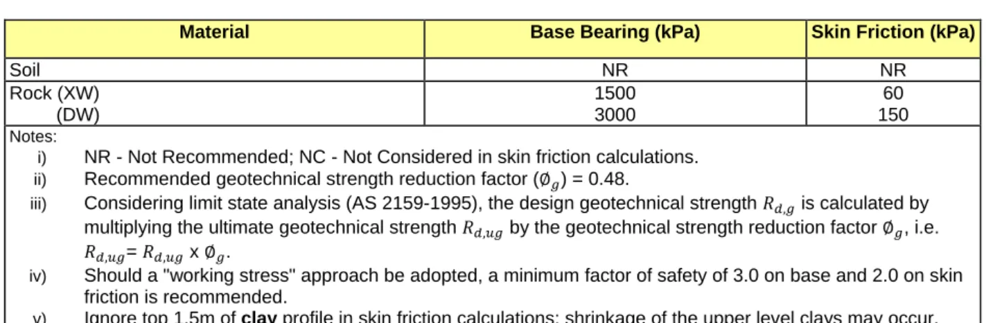
The design geotechnical strength ( , ) can be calculated as the design ultimate geotechnical strength ( , ) multiplied by the geotechnical strength reduction factor ∅ ). The ultimate geotechnical strength parameters for the materials encountered on the site are outlined in Table 4.
TABLE 4 ULTIMATE GEOTECHNICAL STRENGTH PARAMETERS
Material Base Bearing (kPa) Skin Friction (kPa)
Soil NR NR Rock (XW) (DW) 1500 3000 60 150 Notes:
i) NR - Not Recommended; NC - Not Considered in skin friction calculations. ii) Recommended geotechnical strength reduction factor (∅ ) = 0.48.
iii) Considering limit state analysis (AS 2159-1995), the design geotechnical strength , is calculated by multiplying the ultimate geotechnical strength , by the geotechnical strength reduction factor ∅ , i.e.
, = , x ∅ .
iv) Should a "working stress" approach be adopted, a minimum factor of safety of 3.0 on base and 2.0 on skin friction is recommended.
v) Ignore top 1.5m of clay profile in skin friction calculations; shrinkage of the upper level clays may occur.
Slabs
Field and laboratory test results indicate that the existing natural soils, along with any controlled fill, are suitable for slab on ground construction provided that earthworks are carried out in accordance with Section 3.2.
The slab on ground floor should be designed to accommodate the anticipated potential ground surface movement.
Design Considerations Inspections
It is recommended that inspections be undertaken by an experienced and qualified geotechnical engineer from Soil Surveys Engineering following footing excavations to confirm the adequacy of the founding soils. Inspections should be carried out prior to placement of reinforcing steel and ordering of concrete.
Articulation
It is suggested that masonry walls supported on high level footings, be articulated. This articulation may be achieved by the use of full height (footing to eaves) openings or vertical construction joints at regular intervals. Guidelines on articulation are contained in the Cement and Concrete Associations Technical Note 61, "Articulated Walling".
Underground Services & Adjacent Retaining Wall
Where footings are located adjacent to underground services or on top of retaining walls, the footings should extend to base a minimum of 200mm below the trench base/retaining wall footing level for a distance of 1.0m out from the trench. Beyond 1.0m the footings should be taken a minimum of 200mm below an imaginary line drawn up at 450 from the trench base/retaining wall footing level (Figure 2).
3.5 Pavements
Design Values
It is understood that both rigid and flexible pavements may be adopted on the site.
Borehole 1 was drilled to assess subgrade conditions. Laboratory testing of the natural clay material produced a Soaked CBR value of 11%.
This value represents the subgrade strength available in the on-site material compacted to 98% standard density ratio and then subjected to saturation. This situation could occur in the long term if proper site drainage and maintenance procedures are not adopted.
Based on the above and providing that the recommendations outlined in the following section are complied with, the following pavement design values may be adopted for the development. TABLE 5 DESIGN VALUES
Material CBR Value (%) Modulus of Subgrade Reaction (kPa/mm)
Controlled Fill (1) 10
15
53 60
Clay Soil 8 48
Note: (1) Use CBR value of material, see Section 3.2
Construction Considerations
Along with recommendations contained in Sections 3.1 and 3.2, the following general earthworks recommendations are made:-
i) Incorporate a perimeter drain at the pavement edges to prevent possible deterioration under wet weather.
ii) Pavements should be well drained both during and upon completion of construction. Water should not be allowed to pond on or near pavement surfaces.
iii) Pavement gravel should comply with the Local Council quality specifications for sub base and base course material.
iv) Subgrades should be compacted to achieve the minimum density ratios as outlined in Section 3.2 ‘Civil Works’.
1 1
1m
200mm
Found footings below these lines
FIGURE 2
Service Trench or Retaining Wall
v) It is recommended that inspection and testing be carried out following general earthworks to confirm subgrade conditions.
vi) Concrete pavements should preferably be keyed and dowelled at transverse joints and keyed and tied at longitudinal joints.
3.6 Slope Stability
General
As assessment of the stability of the existing cut batter located to the north east of the proposed building was requested as well as comments on the possible effects of the proposed development on this batter.
Mapping
An experienced engineering geologist inspected the batter and the following was noted:-
The rock which outcrops in the batter was described as a distinctly to slightly weathered meta sandstone of the Neranleigh-Fernvale Beds.
Structured defect mapping was undertaken on the available defects and the results were plotted on Figure 3.
A review of this plot indicates that two major (one being bipolar) defect sets (A, A’ and B) and several minor defect sets (C and D) were identified in the data.
Possible Failures
Using these defect sets an analysis of the data was undertaken to identify possible failure modes within the rock mass.
The following comment can be made:-
o Plane failure – there is a potential for plane failure in the existing cut batter along set B. An assessment of the likelihood for this type of failure would be considered unlikely given the average dip angle of the defect set is at or slightly steeper than the existing cut face – Likelihood - UNLIKELY.
o Wedge failure - An assessment of the planes suggests that the intersection of any two planes does not daylight in the face therefore the formation of a wedge type failure is unlikely – Likelihood – RARE TO BARELY CREDIBLE.
o Circular failure – given the rock mass is not highly fractured and the rock mass strength is moderate to high and the likely that circular failures will occur in the soil or extremely weathered section of the cut i.e. the top 1.0m or less.
o Toppling failure –the rock defects mapped do not suggest that toppling failure is likely – Likelihood - UNLIKELY
o Ravelling – ravelling failure of rock cuts is common and unusually related to the rock and degree of weathering of the soil. Based on site observations it is expected this is likely of ravelling failure could be described as possible – Likelihood – POSSIBLE.
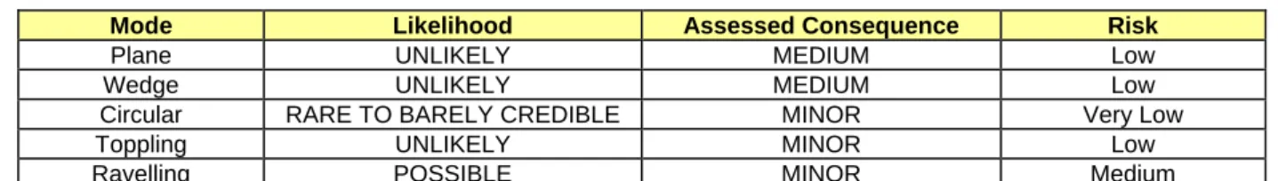
Assessment of Risk
Based on the above failure modes an assessment of the potential consequences to property if they were to occur was made. Using the likelihood and consequence a risk assessment has also been done as per AGS (2007c) Practice Note Guidelines for Landslide Risk Management 2007 Appendix C, and is outlined in Table 6.
TABLE 6 DESIGN VALUES
Mode Likelihood Assessed Consequence Risk
Plane UNLIKELY MEDIUM Low
Wedge UNLIKELY MEDIUM Low
Circular RARE TO BARELY CREDIBLE MINOR Very Low
Toppling UNLIKELY MINOR Low
Ravelling POSSIBLE MINOR Medium
Of the above only Ravelling failure was assessed as being a moderate risk, it is expected that as this occurs regular maintenance work would remove any failed material.
Comments Regarding Proposed Developments
It should be noted that the effect of the proposed development would greatly depend upon the design and construction method of the development.
A preliminary site layout has been provided which suggests that the proposed building will be located approximately 4m to 5m from the top of the existing cut. At present no information with respect to the proposed platform level has been provided and therefore no indication as to the amount and location of the cut and fill to be undertaken on site can been made.
For example:-
Should all earthworks and constructions works not come any closer than say 3m of the top of the existing cut. Then such works are unlikely to effect the existing stability of the cut or the cut effect the development.
Should the entire area over be stripped and machinery access directly above the cut, damage to the cut may occur potentially increasing the risk of slope instability.
Should the proposed development include a fill batter that intrudes into a zone (say 3m
behind the top of the cut) this additional surcharge may effect the stability of the current batter.
Should the proposed development cause a change in surface water flow such that active flows to/over the crest of the cut, this will most probably effect the stability of the cut.
3.7 Retention Design
General
It is understood that retaining walls may be required for the sections of the proposed development, if constructed. The expected maximum retained height may be up to 3.5m.
Pressure Distribution
The lateral earth pressure distribution that affects the retaining walls on the site will depend upon the following parameters:-
Insitu and backfill material properties
Design water regime at the rear of the wall
Wall and cut geometry
Surcharges effecting the wall
Wall type
The structural bracing of the wall and the timing of backfilling behind the wall The following situations should be considered:-
For cantilever walls, which allow some movement at the top, (ie. at least 0.005H in clays) the active case (Ka) applies with a triangular distribution in both the short and long term situations.
For cantilever walls which cannot tolerate this movement, the at rest case (Ko) applies with a triangular distribution in both the short and long term situations.
For structurally braced walls the wall design should be checked for both a trapezoidal (clay soils - short term conditions) and triangular distribution with Ko values (long term conditions).
The pressure distributions as referred to above are shown in Figures 4 and 5. The parameters selected for use in the figures are dependent on the preconstruction geometry of the face being retained. Where the material has been cut using the recommendations (or flatter) as outlined in Section 3.1, the backfill parameters will control. Where a steeper angle is used the earth parameters will control.
The lateral pressure distributions shown in Figures 4 and 5 include hydrostatic pressure and show typical pressure distributions due to surcharge loadings. It is recommended that where the retaining walls are expected to be surcharged (eg. by footings, traffic loads, sloping ground surface, etc.) Soil Surveys Engineering should be contacted to provide a recommended lateral earth pressure distribution.
As a general guide (using an elastic model) line loads located 2.5H away from the wall (where H is the wall height) results in lateral forces of less than 10% of the line load. Parameters for assessment of lateral earth pressures are outlined in Table 7.
K(H-hw) K H + hw w(1-K) H hw TRIANGULAR DISTRIBUTION
+
Lateral Earth Pressure Lateral Pressure Due to Surcharge
+
UDL Point Load or
Strip Footing K = appropriate earth pressure coefficent
H = Vertical height of the wall hw = Height of design water table = Soil bulk density (kN/m3) w = Water bulk density (kN/m3)
FIGURE 4 TRAPEZOIDAL DISTRIBUTION
OR
Clay/Weathered Rock 0.4 H Sand or Gravel 0.65 Ka H H + +UDL Point Load or
Strip Footing Lateral Pressure Due to Surcharge + Hydrostatic Pressure hw FIGURE 5
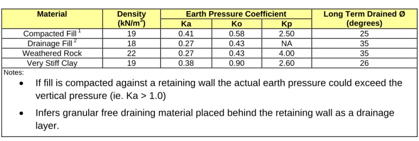
TABLE 7 RETAINING WALL DESIGN PARAMETERS (UNFACTORED)
Material Density
(kN/m3)
Earth Pressure Coefficient Long Term Drained Ø (degrees)
Ka Ko Kp
Compacted Fill 1 19 0.41 0.58 2.50 25
Drainage Fill 2 18 0.27 0.43 NA 35
Weathered Rock 22 0.27 0.43 4.00 35
Very Stiff Clay 19 0.38 0.90 2.60 26
Notes:
If fill is compacted against a retaining wall the actual earth pressure could exceed the vertical pressure (ie. Ka > 1.0)
Infers granular free draining material placed behind the retaining wall as a drainage layer.
Water Regime
Due to possible long term problems with blocking of gravel filters and drains and short term storm conditions that could flood the fill behind retaining walls, it is recommended that all retaining walls be designed for some water pressure distribution. A suggested water pressure distribution for retaining walls on this site would be half height water pressure.
Resistance To Lateral Forces
Resisting forces to sliding and rotation are provided by the shear resistance at the concrete footing/soil or rock interface and the passive soil resistance in front of the footing or shear key, for which the following design parameters are presented:-
Base friction for walls without a key may be taken as tan (2/3 Ø). If the wall has a i)
shallow base key the shearing resistance may be based on tan Ø. Refer to Table 7 for shear angle.
Soil density as in Table 7. ii)
The passive pressure coefficient Kp as in Table 7. iii)
Base bearing capacity as in Section 3.3. iv)
Retaining walls can be designed to resist lateral pressure distribution in several ways ie.
Passive resistance at the toe of the wall
Passive resistance at the key of the wall
Frictional resistance due to the weight of the wall
Because the resistance can be effected by various parameters, Soil Surveys Engineering should be contacted once a general wall geometry has been identified to provide further comment.
Design Requirements
It is recommended that any retaining structure is designed in accordance with AS4678-2002 ‘Earth Retaining Structures’.
Construction Details
With all retaining walls, it is essential that adequate drainage be provided behind the wall. Any backfill placed behind the wall should be loose granular material. The backfill should not be heavily compacted since research has shown that compaction can raise the earth pressure to above the 'at rest' pressure. A permeable geofabric should be placed between the natural soils and the loose granular backfill to prevent fine material piping out of the natural soils and blocking the backfill.
During installation of any retaining walls, the insitu soils should be battered back to minimise fall-in and subsequent disruption of works. Temporary batter angles are given in Section 3.1. Suitable precautions to satisfy Health & Safety requirements must also be adhered to; a maximum unsupported height of 1.5m is recommended.
3.8 Site Management
It is important that proper site management for the existing soil conditions are observed by both the builder at the time of the construction and the owner throughout the life of the proposed development.
Particular reference to this is set out in AS2870-2011. It should be noted that where proper site management, particularly with respect to change in moisture conditions, is not followed, the foundation recommendations contained in this report could be considered void.
The following are some specific comments with respect to site management and the reader is also directed to CSIRO pamphlet, 10-91, ‘to Home Owners on Foundation Maintenance and Footing Performance’ for further information:-
It is important that the site be well drained. The ground around the building should slope away at 1 in 20 for 2 metres and then fall to the stormwater system to prevent ponding of water adjacent to the building.
Roof downpipes and garden taps should not be allowed to saturate founding soils.
Do not let the slab subgrade "dry out" prior to casting.
Future shrubs and trees should be planted at a distance at least equivalent to three quarters of their mature height away from the building to avoid shrinkage movement in the potentially expansive founding soils. Existing trees that may encroach this restriction should be removed. It is recommended that trees to be removed be removed as early as possible prior to building construction to enable soil moisture to reach equilibrium.
4.0 LIMITATIONS
We have prepared this report for the use of Capworks Management QLD Pty Ltd, for design purposes in accordance with generally accepted geotechnical engineering practices. No other warranty, expressed or implied, is made as to the professional advice included in this report. This report has not been prepared for use by parties other than Capworks Management QLD Pty Ltd. It may not contain sufficient information for purposes of other parties or for other uses. Your attention is drawn to ‘Appendix A’, ‘Notes Relating to this Report’. Interpretation of factual data given in this report is based on judgement, not a greater knowledge of facts other than those reported.
0.10 0.20
0.80
1.30
NATURAL Silty Gravelly SAND (SM) Medium dense, grey, fine to medium grained, fine sized gravel, organics throughout, moist (topsoil).
Silty Gravelly SAND (SM) Medium dense, grey, fine to medium grained, fine sized gravel, moist (topsoil). Sandy CLAY (CI) Hard, medium plasticity, mottled yellow brown-grey, fine to medium coarse sand, moist.
METASANDSTONE (DW) Medium strong, mottled light grey yellow brown, moist.
BOREHOLE BH 01 TERMINATED AT 1.30 m U50 PP>600 CBR Drilling Method RR WB TC Description Cas ing NMLC Depth 0.5 1.0 1.5 2.0 2.5 3.0 Graph ic
Water First Noted Water Steady Level
Approved:
Date: 30/10/2014 NTP Comments:
1) Groundwater not encountered. 2) DCP Refusal at 0.9m. Samples and Remarks U50 SPT Disturbed Sample Samples Weathering Grades Rock Strength RS - Residual Soil XW - Extremely weathered DW - Distinctly weathered SW - Slightly weathered FR - Fresh VW - Very weak W - Weak MS - Medium strong S - Strong VS - Very strong ES - Extremely strong S OI L_SURVE Y S _00 LI B RARY 2012-05.GLB Log S OI L_SURVE Y _AUGE R_LOG 2-1 1895.GP J <<Dr awingFile>> 30/10/ 2014 14:38 8.30. 003 Dev eloped by Datgel Page: 1 OF 1 Project Name: Proposed Trade Skills Centre
Location: Nerang State High School Client: Capworks Management QLD Date: 13/10/2014 Easting: 532316 Logger: TE Northing: 6902497 Jacro 105 RL: Machine: Operator: TE DCP Test (blows/100mm) 6 12 18 24 0 30
0.60
0.80
NATURAL METASANDSTONE (XW) Extremely weak, mottled yellow brown very light grey, moist.
METASANDSTONE (DW) Medium strong, mottled yellow brown very light grey, moist.
BOREHOLE BH 02 TERMINATED AT 0.80 m D Drilling Method RR WB TC Description Cas ing NMLC Depth 0.5 1.0 1.5 2.0 2.5 3.0 Graph ic
Water First Noted Water Steady Level
Approved:
Date: 30/10/2014 NTP Comments:
1) Groundwater not encountered. 2) DCP refusal at 0.1m and 0.9m. Samples and Remarks U50 SPT Disturbed Sample Samples Weathering Grades Rock Strength RS - Residual Soil XW - Extremely weathered DW - Distinctly weathered SW - Slightly weathered FR - Fresh VW - Very weak W - Weak MS - Medium strong S - Strong VS - Very strong ES - Extremely strong S OI L_SURVE Y S _00 LI B RARY 2012-05.GLB Log S OI L_SURVE Y _AUGE R_LOG 2-1 1895.GP J <<Dr awingFile>> 30/10/ 2014 14:38 8.30. 003 Dev eloped by Datgel Page: 1 OF 1 Project Name: Proposed Trade Skills Centre
Location: Nerang State High School Client: Capworks Management QLD Date: 13/10/2014 Easting: 532290 Logger: TE Northing: 6902495 Jacro 105 RL: Machine: Operator: TE DCP Test (blows/100mm) 6 12 18 24 0 30
0.20
0.89 0.90
NATURAL Gravelly SAND (SP) Medium dense, grey, fine to medium grained, fine size gravel, organic throughout, moist.
METASANDSTONE (XW) Extremely weak, mottled yellow brown very light grey, moist.
METASANDSTONE (DW) Moderately strong, mottled yellow brown very light grey, moist.
BOREHOLE BH 03 TERMINATED AT 0.90 m CBR Drilling Method RR WB TC Description Cas ing NMLC Depth 0.5 1.0 1.5 2.0 2.5 3.0 Graph ic
Water First Noted Water Steady Level
Approved:
Date: 30/10/2014 NTP Comments:
1) Groundwater not encountered. 2) DCP refusal at 0.3m. Samples and Remarks U50 SPT Disturbed Sample Samples Weathering Grades Rock Strength RS - Residual Soil XW - Extremely weathered DW - Distinctly weathered SW - Slightly weathered FR - Fresh VW - Very weak W - Weak MS - Medium strong S - Strong VS - Very strong ES - Extremely strong S OI L_SURVE Y S _00 LI B RARY 2012-05.GLB Log S OI L_SURVE Y _AUGE R_LOG 2-1 1895.GP J <<Dr awingFile>> 30/10/ 2014 14:38 8.30. 003 Dev eloped by Datgel Page: 1 OF 1 Project Name: Proposed Trade Skills Centre
Location: Nerang State High School Client: Capworks Management QLD Date: 13/10/2014 Easting: 532260 Logger: TE Northing: 6902522 Jacro 105 RL: Machine: Operator: TE DCP Test (blows/100mm) 6 12 18 24 0 30
0.10
0.26
1.10 1.20
NATURAL Gravelly SAND (SP) Medium dense, grey, fine to medium grained, fine size gravel, organics throughout, moist.
Gravelly SAND (SP) Medium dense, grey, fine to medium grained, fine size gravel, moist.
METASANDSTONE (XW) Weak, mottled yellow brown very light grey, moist.
METASANDSTONE (DW) Moderately strong, mottled yellow brown very light grey, moist. BOREHOLE BH 04 TERMINATED AT 1.20 m D Drilling Method RR WB TC Description Cas ing NMLC Depth 0.5 1.0 1.5 2.0 2.5 3.0 Graph ic
Water First Noted Water Steady Level
Approved:
Date: 30/10/2014 NTP Comments:
1) Groundwater not encountered. 2) DCP refusal at 0.4m. Samples and Remarks U50 SPT Disturbed Sample Samples Weathering Grades Rock Strength RS - Residual Soil XW - Extremely weathered DW - Distinctly weathered SW - Slightly weathered FR - Fresh VW - Very weak W - Weak MS - Medium strong S - Strong VS - Very strong ES - Extremely strong S OI L_SURVE Y S _00 LI B RARY 2012-05.GLB Log S OI L_SURVE Y _AUGE R_LOG 2-1 1895.GP J <<Dr awingFile>> 30/10/ 2014 14:38 8.30. 003 Dev eloped by Datgel Page: 1 OF 1 Project Name: Proposed Trade Skills Centre
Location: Nerang State High School Client: Capworks Management QLD Date: 13/10/2014 Easting: 532281 Logger: TE Northing: 6902538 Jacro 105 RL: Machine: Operator: TE
Sample Details
Sample ID: WHL14-1401-S1 Sampling Method: As Supplied
Field ID: N/A Material: N/A
Date Sampled: 13/10/2014 Source: Borehole
Date Submitted: N/A Specification: N/A
Project Location: Nerang SHS
Sample Location: BH1, 0.4m
Borehole Number: N/A
Borehole Depth (m):N/A
Shrink Test AS 1289.7.1.1
Shrink on drying (%): 0.4
Shrinkage Moisture Content (%):14.5
Est. inert material (%): N/A
Crumbling during shrinkage: N/A
Cracking during shrinkage: SLIGHT
Swell Test AS 1289.7.1.1
Swell on Saturation (%): 6.2
Moisture Content before (%): 14.9
Moisture Content after (%): 20.4
Est. Unc. Comp. Strength before (kPa):N/A
Est. Unc. Comp. Strength after (kPa): N/A
Shrink Swell
-10.0 -8.0 -6.0 -4.0 -2.0 0.0 2.0 4.0 6.0 8.0 10.0 5.0 10.0 15.0 20.0 25.0 30.0 35.0 40.0 45.0 50.0 S h ri n k ( % ) E s h S w e ll (% ) E s w Moisture Content (%) Shrinkage SwellShrink Swell Index - Iss (%):
2.0
This document is issued in accordance with NATA's accreditation requirements.
25/10/2014
Shrink Swell Index Report
Report No: SSI:WHL14-1401-S1 Issue No: 1
Client:
Date of Issue: NATA Accredited
Laboratory Number:
Approved Signatory: C.Ferguson-Hannah (Senior Technician)
Australia
Ph:+61 7 5502 6795 Fax:+61 7 5502 6724
Capworks Management QLD Pty Ltd Helensvale QLD 4212
C/O 8/140 Millaroo Drive
THIS DOCUMENT SHALL NOT BE REPRODUCED EXCEPT IN FULL
15301
Project: Proposed School Building
Project Location: Project Number:
Nerang SHS 2-11895
Page 1 of 1
Form No: 18932, Report No: SSI:WHL14-1401-S1 © 2000-2012 QESTLab by SpectraQEST.com
DESCRIPTION: SANDY CLAY(CI-CH) BROWN UNIT WEIGHT: 2.08 t/m3
Borehole Source: Unknown Material:
Sample Details
WHL14-1393-S1 Sample ID: 13/10/2014 Date Sampled: Specification: As Supplied Sampling Method:Silty Sand (SM) Brown
Soil Description:
SSE
Sampled By: Field Sample ID:
BH1 Location Description: 0.2-0.7m
Test Results
11 17/10/2014 N/A N/A 15.0 1.74 17/10/2014 9.7 ResultMoisture Content [AS 1289.2.1.1]
Method
Description Limits
Moisture Content (%) Date Tested
Maximum Dry Density - Standard [AS 1289.5.1.1] Standard Maximum Dry Density (t/m³)
Standard Optimum Moisture Content (%) Oversize Sieve (mm)
Oversize Material (%) Date Tested
California Bearing Ratio [AS 1289.6.1.1]
CBR At 5.0mm (%)
1.74 Maximum Dry Density (t/m³)
15.0 Optimum Moisture Content (%)
1.75 Dry Density before Soaking (t/m³)
101 Density Ratio before Soaking (%)
14.3 Moisture Content before Soaking (%)
96 Moisture Ratio before Soaking (%)
1.75 Dry Density after Soaking (t/m³)
101 Density Ratio after Soaking (%)
0.0 Swell (%)
17.9 Moisture Content of Top 30mm (%)
17.9 Moisture Content of Remaining Depth (%)
Standard Compactive Effort
4.50 Surcharge Mass (kg)
4 Period of Soaking (Days)
0.0 Oversize Material (%)
22/10/2014 Date Tested
This document is issued in accordance with NATA's accreditation requirements.
23/10/2014
Material Test Report
Report No: MAT:WHL14-1393-S1 Issue No: 1
Client:
Date of Issue: NATA Accredited
Laboratory Number:
Approved Signatory: Rod Lucas (Senior Tech)
Australia
Ph:+61 7 5502 6795 Fax:+61 7 5502 6724
Capworks Management QLD Pty Ltd Helensvale QLD 4212
C/O 8/140 Millaroo Drive
THIS DOCUMENT SHALL NOT BE REPRODUCED EXCEPT IN FULL
15301
Project: Proposed School Building
Project Location: Project Number: Nerang SHS 2-11895 Page 1 of 1 © 2000-2012 QESTLab by SpectraQEST.com
Form No: 18909, Report No: MAT:WHL14-1393-S1
N/A
2-11895-01 E xis ting ro ck c ut
P
R
O
P
O
S
E
D
B
U
IL
D
IN
G
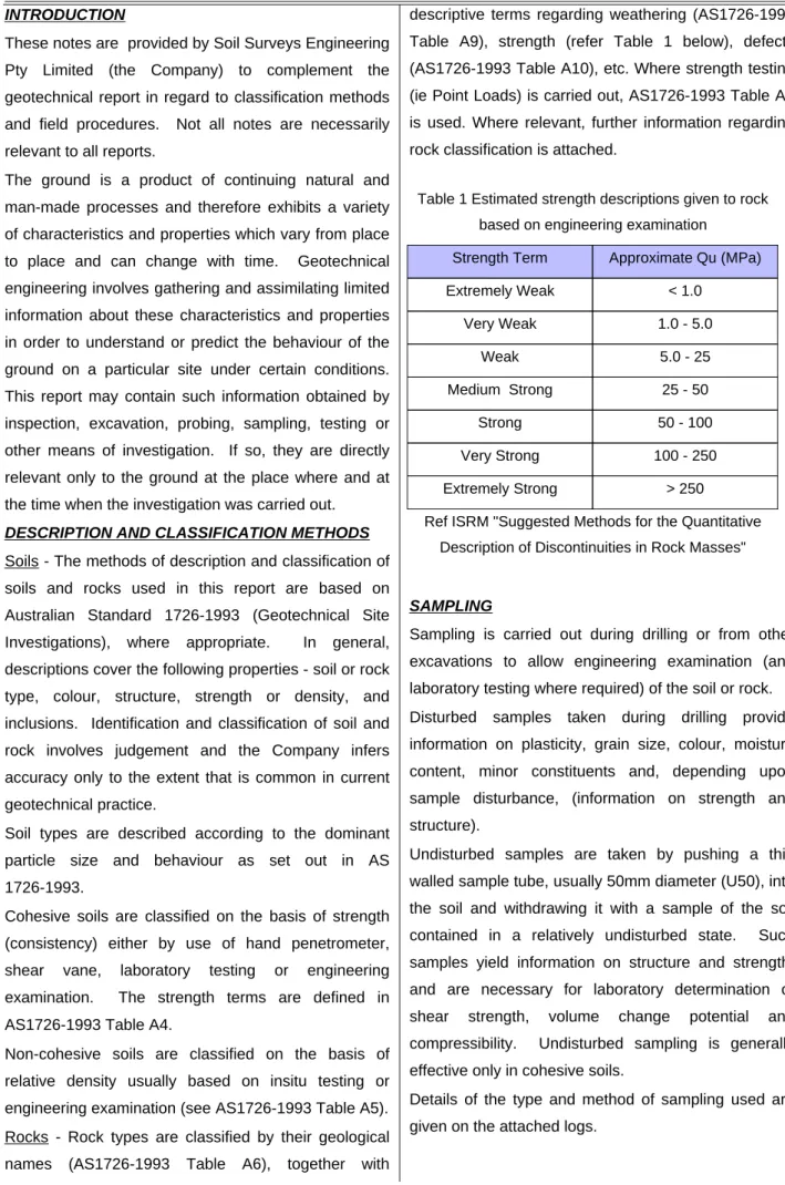
BH 01 BH 02 BH 03 BH 04 532230 532250 532270 532290 532310 532330 6902480 6902490 6902500 6902510 6902520 6902530 6902540 6902550These notes are provided by Soil Surveys Engineering Pty Limited (the Company) to complement the geotechnical report in regard to classification methods and field procedures. Not all notes are necessarily relevant to all reports.
The ground is a product of continuing natural and man-made processes and therefore exhibits a variety of characteristics and properties which vary from place to place and can change with time. Geotechnical engineering involves gathering and assimilating limited information about these characteristics and properties in order to understand or predict the behaviour of the ground on a particular site under certain conditions. This report may contain such information obtained by inspection, excavation, probing, sampling, testing or other means of investigation. If so, they are directly relevant only to the ground at the place where and at the time when the investigation was carried out.
DESCRIPTION AND CLASSIFICATION METHODS
Soils - The methods of description and classification of soils and rocks used in this report are based on Australian Standard 1726-1993 (Geotechnical Site Investigations), where appropriate. In general, descriptions cover the following properties - soil or rock type, colour, structure, strength or density, and inclusions. Identification and classification of soil and rock involves judgement and the Company infers accuracy only to the extent that is common in current geotechnical practice.
Soil types are described according to the dominant particle size and behaviour as set out in AS 1726-1993.
Cohesive soils are classified on the basis of strength (consistency) either by use of hand penetrometer, shear vane, laboratory testing or engineering examination. The strength terms are defined in AS1726-1993 Table A4.
Non-cohesive soils are classified on the basis of relative density usually based on insitu testing or engineering examination (see AS1726-1993 Table A5). Rocks - Rock types are classified by their geological names (AS1726-1993 Table A6), together with
Table A9), strength (refer Table 1 below), defects (AS1726-1993 Table A10), etc. Where strength testing (ie Point Loads) is carried out, AS1726-1993 Table A8 is used. Where relevant, further information regarding rock classification is attached.
SAMPLING
Sampling is carried out during drilling or from other excavations to allow engineering examination (and laboratory testing where required) of the soil or rock. Disturbed samples taken during drilling provide information on plasticity, grain size, colour, moisture content, minor constituents and, depending upon sample disturbance, (information on strength and structure).
Undisturbed samples are taken by pushing a thin walled sample tube, usually 50mm diameter (U50), into the soil and withdrawing it with a sample of the soil contained in a relatively undisturbed state. Such samples yield information on structure and strength, and are necessary for laboratory determination of shear strength, volume change potential and compressibility. Undisturbed sampling is generally effective only in cohesive soils.
Details of the type and method of sampling used are given on the attached logs.
NOTES RELATING TO THIS REPORT - SEPT 2013 SOIL SURVEYS ENGINEERING
Ref ISRM "Suggested Methods for the Quantitative Description of Discontinuities in Rock Masses"
> 250 Extremely Strong 100 - 250 Very Strong 50 - 100 Strong 25 - 50 Medium Strong 5.0 - 25 Weak 1.0 - 5.0 Very Weak < 1.0 Extremely Weak Approximate Qu (MPa) Strength Term
Table 1 Estimated strength descriptions given to rock based on engineering examination
Test locations (e.g. boreholes, CPT’s, test pits etc.) were based on available access at the time of testing (access may need to be provided “by others”). Test locations may have been shifted if access was not suitable.
Unless noted otherwise, accuracy of test locations are to the accuracy of hand held GPS equipment.
INVESTIGATION METHODS
The following is a brief summary of investigation methods currently adopted by the Company and some comments on their use and application.
Test Pits - These are normally excavated with a
backhoe or a tracked excavator, allowing close examination of the insitu soils if it is safe to descend into the pit. The depth of penetration is limited to about 3m for a backhoe and up to 6m for an excavator. Limitations of test pits are the problems associated with disturbance and difficulty of reinstatement and the consequent effects on close-by structures. Care must be taken if construction is to be carried out near test pit locations to either properly recompact the backfill during construction or to design and construct the structure so as not to be adversely affected by poorly compacted backfill at the test pit location.
Hand Auger Drilling - A borehole of 50 to 100mm
diameter is advanced by manually operated equipment. Refusal of the augers can occur on a variety of materials such as hard clay, gravel or rock fragments and does not necessarily indicate rock level.
Continuous Spiral Flight Augers - The borehole is
advanced using 75 to 300 mm diameter continuous spiral flight augers, which are withdrawn at intervals to allow sampling or insitu testing. This is a relatively economical means of drilling in clays and in sands above the water table. Samples are returned to the surface by the flights or may be collected after withdrawal of the augers. Information from the drilling (as distinct from specific sampling) is of relatively lower reliability due to remoulding, inclusion of cuttings from above or softening of samples by groundwater, or uncertainties as to the original depth of the samples. Augering below the groundwater table has a lower reliability than augering above the water table. Various drill bits are attached to the base of the augers during
types can provide information as to the strength of the material encountered. Generally two different bit types are used. The 'V' bit is a V shaped steel bit and the 'TC' bit is a tungsten carbide tipped screw type bit.
Wash Boring - The borehole is usually advanced by a
rotary bit with water or fluid pumped down the hollow drill rods and returned up in the space between the rods and the soil or casing, carrying the drill cuttings. Only major changes in stratification can be determined from the cuttings, together with some information from "feel" and rate of penetration. More accurate information on soil strata is gained by regular testing and sampling using the Standard Penetration Test (SPT) and undisturbed thin walled tube samples (U50).
Mud Stabilized Drilling - Either Wash Boring or
Continuous Core Drilling can use drilling mud as a circulating fluid to stabilize the borehole. The term "mud" encompasses a range of products ranging from bentonite to polymers such as Revert or Biogel. The mud tends to mask the cuttings and reliable identification is only possible from regular intact sampling (eg. from SPT and U50 samples) or from rock coring, etc.
Continuous Core Drilling - A continuous core sample
is obtained using a diamond or tungsten carbide tipped core barrel. Provided full core recovery is achieved (which is not always possible in very weak rocks and granular soils), this technique provides a very reliable method of investigation. In rocks, NMLC coring (nominal 52 mm diameter) is usually used with water flush. The length of core recovered is compared to the length drilled and any length not recovered is shown as CORE LOSS. The location of losses is determined on site by the supervisor. If the location of the loss is uncertain, it is placed at the top end of the run, when the core is placed in a storage tray and recorded on the log.
Standard Penetration Tests - Standard Penetration
Tests (SPT) are used mainly in non-cohesive soils, but can also be used in cohesive soils, as a means of indicating density or strength. The test procedure is described in Australian Standard 1289, "Methods of Testing Soils for Engineering Purposes" - Test 6.3.1.
diameter split sample tube with a tapered shoe, under the impact of a 63 kg hammer with a free fall of 760 mm. It is normal for the tube to be driven in three successive 150 mm increments and the 'N' value is taken as the number of blows for the last 300 mm, the upper 150 mm being neglected due to possible disturbance from the drilling method. In dense sands, very hard clays or weak rock, the full 450 mm penetration may not be practicable and the test is discontinued at a reduced penetration.
In the case where full penetration is obtained with successive blow counts for each 150 mm of, say 4, 6 and 7 blows, the record shows,
4, 6, 7 N = 13 In a case where the test is discontinued short of full penetration, say after 15 blows for the first 150 mm and 30 blows for the next 40 mm, the record shows:
15, 30/40mm
The results of the test can be related empirically to the engineering properties of the soil.
Occasionally, the drop hammer is used to drive 50mm diameter thin walled sample tubes (U50) in clays. In such circumstances, it is noted on the borehole logs. A modification to the SPT test is where the same driving system is used with a solid 600 tipped steel
cone of the same diameter as the SPT hollow sampler. The solid cone can be continuously driven for some distance in soft clays or loose sands, or may be used where damage would otherwise occur to the SPT. The results of this Solid SPT are shown as "Nc" on the
borehole logs, together with the number of blows per 150 mm penetration.
Cone Penetration Tests - Test Method - Cone
Penetration Tests (CPT) are carried out in accordance with AS 1289 Test 6.5.1-1977, using an electrical friction-cone penetrometer.
The test essentially comprises the measurement of resistance to penetration of a cone of 35.7 mm diameter pushed into the soil at a rate of 10-20 mm per second by hydraulic force. The resistance to penetration is recorded in terms of pressure on the end area of the cone (cone resistance, qc, in MPa) and
friction on the side of the 135 mm long sleeve immediately above the top of the cone (friction
electrical transducers (strain gauges) within the cone device. The ratio between friction resistance and cone resistance is also calculated as a percentage,
ie.-Friction RatioFR Friction Resiscone resistantancece,f,sqckPakPa100
The friction ratio, FR, is generally low in sands (less than 1% or 2%) and generally higher in clays (say 3% or more). The interpretation of sandy clays, clayey sands and material with a high silt content is more difficult, but intermediate values (between 1% and 3%) would be expected. Highly organic clays and peats generally have a friction ratio in excess of 5%.
Static cone data is recorded in the field on disc for later presentation using computer aided drafting.
The equipment can be operated from any conventional drill rig. A total applied load in the range of 4 to 10 tonnes is required for practical purposes, although lighter loads may be used. The cone penetrometers are available with various capacities of cone resistance ranging up to 100 MPa for general purpose investigations, while a range of 0 to 10 MPa can be used where more sensitive investigations of soft clay are required.
The cone resistance value provides a continuous measure of soil strength or density, and together with the friction ratio, provide very useful indications of the presence of narrow bands of geotechnically significant layers such as thin, soft clay layers or lenses of sand which might otherwise be missed using conventional drilling methods.
The lithology of the encountered soils is interpreted from static cone data and is generally presented on the static cone log sheets.
It is important to note that the lithology is interpreted information and is based on research by Schmertmann (1970), Sanglerat (1972), Robinson and Campinalli (1986), modified to suit local conditions as indicated by borehole information and laboratory testing.
As soils generally change gradually it is sometimes difficult to accurately describe depths of strata changes, although greater accuracy is obtained with the static cone compared with conventional drilling. In addition, friction ratios decrease in accuracy with low cone resistance values, and in desiccated soils. As a result, some overlap and minor discrepancies may
information.
Portable Dynamic Cone Penetrometers - Portable
Dynamic Cone Penetrometer (DCP) tests are carried out by driving a rod into the ground with a falling weight hammer and measuring the blows for successive 100mm increments of penetration.
The DCP comprises a Cone of 20 mm diameter with 30 degree taper attached to steel rods of smaller section.
The cone end is driven with a 9 kg hammer falling 510 mm (AS. 1289 Test 6.3.2). The test was developed initially for pavement subgrade investigations, and empirical correlations of the test results with California Bearing Ratio have been published by various Road Authorities. The Company has developed their own correlations with Standard Penetration tests and Density Index tests in sands.
LOGS
The borehole or test pit logs presented herein are an engineering and/or geological interpretation of the subsurface conditions, and their reliability will depend to some extent on the frequency of sampling and the method of drilling or excavation. Ideally, continuous undisturbed sampling or core drilling will enable the most reliable assessment but is not always practicable or possible to justify on economic grounds. In any case, the boreholes or test pits represent only a very small sample of the total subsurface conditions. The attached explanatory notes define the terms and symbols used in preparation of the logs.
Interpretation of the information shown on the logs, and its application to design and construction, should therefore take into account the spacing of boreholes or test pits, the method of drilling or excavation, the frequency of sampling and testing and the possibility of other than "straight line" variations between the boreholes or test pits. Subsurface conditions between boreholes or test pits may vary significantly from conditions encountered at the borehole or test pit locations.
Where groundwater levels are measured in boreholes, there are several potential problems.
wAlthough groundwater may be present in lower permeability soils, it may enter the hole slowly or perhaps not at all during the time the hole is open.
wA localized perched water table may lead to an erroneous indication of the true water table.
wWater table levels will vary from time to time with seasons or recent weather changes and may not be the same at the time of construction.
wThe use of water or mud as a drilling fluid will mask any groundwater inflow. Water has to be bailed out of the bore and mud must be washed out of the hole or "reverted" if water observations are to be made. More reliable measurements can be made by use of standpipes which are read after stabilizing at periods ranging from several days to perhaps weeks for low permeability soils. Piezometers, sealed in a particular stratum, may be advisable in low permeability soils or where there may be interference from perched water tables or surface water.
FILL
The presence of fill materials can often be determined only by the inclusion of foreign objects (eg. bricks, steel, etc.) or by distinctly unusual colour, texture or fabric. Identification of the extent of fill materials will also depend on investigation methods and frequency. Where natural soils similar to those at the site are used for fill, it may be difficult with limited testing and sampling to reliably determine the extent of the fill. The presence of fill materials is usually regarded with caution as the possible variation in density, strength and material type is much greater than with natural soil deposits. Consequently, there is an increased risk of adverse engineering characteristics or behaviour. If the volume and quality of fill is important to a project, then frequent test pit excavations are preferable to boreholes.
Laboratory testing is normally carried out in accordance with Australian Standard 1289 "Methods of Testing Soil for Engineering Purposes". Details of the test procedure used are given on the individual report forms and the attached explanatory notes summarize important aspects of the Laboratory Test Procedures adopted.
ENGINEERING REPORTS
Engineering reports are prepared by qualified personnel and are based on the information obtained and on current engineering standards of interpretation and analysis. The information provided in Soil Surveys Engineering reports is opinion and interpretation and not factual. The client/contractor increases their risk by not retaining the person who authored the geotechnical report, to carry out site inspection and review (overseeing role) during construction, to confirm opinion and interpretation expressed in the report is accurate. Where the report has been prepared for a specific design proposal the information and interpretation may not be relevant if the design proposal is changed. If this happens, the Company will be pleased to review the report and the sufficiency of the investigation work.
Every care is taken with the report as it relates to interpretation of subsurface conditions, discussion of geotechnical aspects and recommendations or suggestions for design and construction. Since the test sites in any exploration represent a very small proportion of the total site and since the exploration only identifies actual ground conditions at the test sites, even under the best circumstances actual conditions may vary from those inferred to exist. No responsibility is taken
for:-wUnexpected variations in ground and/or groundwater conditions.
wChanges in policy or interpretation of policy by statutory authorities.
wThe actions of other persons.
wAny work where the company is not given the opportunity to supervise the construction using the Companies designs/recommendations.
assist with investigation or advice to resolve any problems occurring.
SITE ANOMALIES
In the event that conditions encountered on site during construction appear to vary from those expected from the information contained in the report, the Company requests that it immediately be notified. Most problems are more readily resolved when conditions are exposed than at some later stage, well after the event.
Extreme events including but not limited to the results of climate change, eg. flood levels above previously identified levels, beach scour or erosion beyond normal expectations (as identified by local authorities) extreme rainfall events, war, espionage, sabotage may result in different conditions between time of investigation and time of construction.
REPRODUCTION OF INFORMATION FOR CONTRACTUAL PURPOSES
Attention is drawn to the document “Guidelines for the Provision of Geotechnical Information in Construction Contracts (1987)”, published by the Institution of Engineers, Australia. Where information obtained from this investigation is provided for tendering purposes, it is recommended that all information, including the written report and discussion, be made available. In circumstances, where the discussion or comments section is not relevant to the contractual situation, it may be appropriate to prepare a specially edited document. The Company would be pleased to assist in this regard and/or to make additional report copies available for contract purposes at a nominal charge.
REVIEW OF DESIGN
Where major civil or structural developments are proposed or where only a limited investigation has been completed or where the geotechnical conditions/ constraints are quite complex, it is prudent to have a joint design review which involves a senior geotechnical engineer. We would be happy to assist in this regard as an extension of our investigation commission. Construction drawings should be reviewed by Soil Surveys Engineering, with sufficient time to allow changes if required, prior to inspections.
to refuse to carry out inspections.
SITE INSPECTION
The Company will always be pleased to provide engineering inspection services for geotechnical aspects of work to which this report is related.
i) Site visits during construction to confirm reported ground conditions
ii) Site visits to assist the contractor or other site personnel in identifying various soil/rock types such as appropriate footing or pier founding depths, the stability of a filled or excavated slope; or
iii) Full-time engineering presence on site.
In the vast majority of cases it is advantageous to the principal for the geotechnical engineer who wrote the investigation report to be involved in the construction stage of the project.
The geotechnical engineer cannot take responsibility for variations in encountered conditions, where he is not given the opportunity to review plans for the proposed development with sufficient time to allow review and make changes to the proposed development if required, and where he is not given the opportunity to inspect the site and oversee construction methods with regard to site conditions with sufficient time to observe all relevant site conditions and operations.
RESPONSIBLE USE OF GEOTECHNICAL INFORMATION
Recommendations in our report are for design purposes only and provided on the basis that inspections are carried out to allow finalisation of opinions and recommendations contained in our report.
The geotechnical investigation consisting of field and laboratory testing has been carried out to indicate typical conditions by indicating conditions and parameters at the specific locations of boreholes/test pits. Subsurface conditions are indicated at these locations only and the inference of conditions between or away from these locations (interpolation and extrapolation) involves a certain degree of risk. Persons inferring such conditions or carrying out such inferences should do so with a degree of caution and
consequences of the risk of error.
Estimates of volumes based on our findings require interpolation and extrapolation between test locations and as such may be significantly different from actual volumes.