2017
Enhanced corrosion and wear resistance properties of carbon
Enhanced corrosion and wear resistance properties of carbon
fiber reinforced Ni-based composite coating by laser cladding
fiber reinforced Ni-based composite coating by laser cladding
Jianbo Lei Chuan Shi Shenfeng Zhou Zhenjie Gu Laichang Zhang
Edith Cowan University, l.zhang@ecu.edu.au
Follow this and additional works at: https://ro.ecu.edu.au/ecuworkspost2013 Part of the Materials Science and Engineering Commons
10.1016/j.surfcoat.2017.11.051
Lei, J., Shi, C., Zhou, S., Gu, Z., & Zhang, L. -. (2018). Enhanced corrosion and wear resistance properties of carbon fiber reinforced ni-based composite coating by laser cladding. Surface and Coatings Technology, 334, 274-285. Available here
This Journal Article is posted at Research Online. https://ro.ecu.edu.au/ecuworkspost2013/4002
reinforced Ni-based composite coating by laser cladding
Jianbo Lei, Chuan Shi, Shengfeng Zhou, Zhenjie Gu, Lai-Chang Zhang
PII: S0257-8972(17)31198-2
DOI: doi:10.1016/j.surfcoat.2017.11.051
Reference: SCT 22899
To appear in: Surface & Coatings Technology
Received date: 17 July 2017 Revised date: 10 November 2017 Accepted date: 17 November 2017
Please cite this article as: Jianbo Lei, Chuan Shi, Shengfeng Zhou, Zhenjie Gu, Lai-Chang Zhang , Enhanced corrosion and wear resistance properties of carbon fiber reinforced Ni-based composite coating by laser cladding. The address for the corresponding author was captured as affiliation for all authors. Please check if appropriate. Sct(2017), doi:10.1016/ j.surfcoat.2017.11.051
This is a PDF file of an unedited manuscript that has been accepted for publication. As a service to our customers we are providing this early version of the manuscript. The manuscript will undergo copyediting, typesetting, and review of the resulting proof before it is published in its final form. Please note that during the production process errors may be discovered which could affect the content, and all legal disclaimers that apply to the journal pertain.
ACCEPTED MANUSCRIPT
Enhanced corrosion and wear resistance properties of carbon fiber
reinforced Ni-based composite coating by laser cladding
Jianbo Leia,*, Chuan Shia, Shengfeng Zhoua,*, Zhenjie Gua, Lai-Chang Zhangb,*
aLaser Technology Institute, Tianjin Polytechnic University, Tianjin, 300387, China
bSchool of Engineering, Edith Cowan University, 270 Joondalup Drive, Joondalup,
Perth, WA 6027, Australia
Abstract: To enhance the wear resistance and corrosion resistance of Ni-based coatings,
carbon fibers reinforced nickel-based composite coatings (CFs/Ni) were fabricated on
the surface of 1Cr13 stainless steel by laser cladding (LC). The microstructure
characteristics, microhardness, wear and corrosion performances of the composite
coatings were investigated. The results show that CFs can effectively improve the
corrosion and wear resistances of Ni-based coatings. With increasing laser scanning
speed, the morphology of CFs in composite coatings is more integral and the corrosion
* Corresponding author. Tel.: +86-22-83956392
E-mail address: ljbtj@163.com (J. Lei); zhousf1228@163.com(S. Zhou); lczhangimr@gmail.com; l.zhang@ecu.edu.au (L.C. Zhang)
ACCEPTED MANUSCRIPT
and wear resistances of the composite coatings are improved. Especially, when laser
scanning speed is increased to 8 mm/s, the average microhardness of the composite
coating reaches up to 405 HV0.2, which is about 1.3 times higher than that of Ni-based
coating. Moreover, the corrosion current density and the wear rate of the composite
coating are only 7% and 55% of those of the Ni-based coating, respectively, which is
attributed to the good properties and homogeneous distribution of CFs and finer
microstructure of composite coating.
Keywords: Laser cladding (LC); Carbon fibers; Nickel based coating; Electrochemical
corrosion; Wear mechanisms
1. Introduction
Generally, Ni-based coatings exhibit excellent high-temperature oxidation and
high-temperature wear performances so that they are usually applied in the field of
bearings, engines, piston rods and at some high temperature environments [1]. The
main methods for preparing Ni-based coatings are usually electroplating, thermal
ACCEPTED MANUSCRIPT
electroplating, although the process is matured and the processing cost is relatively low,
the process has some disadvantages. For example, electroplating coatings are very thin
and the interface between coating and substrate is so poor that the electroplating
coatings are susceptible to being peeled off from substrate during service. For thermal
spraying, it has relatively higher efficiency, but the sprayed coatings are mechanically
bonded to substrate and contain many pores and micro-cracks, resulting in premature
failure therefore a decrease in service time [6, 7].
The continuing development of high-power lasers, computers and robots has made
the metal laser additive manufacturing (i.e. metal 3D printing) become one of the hot
spots, because it possesses many advantages as follows [8-12]. First, it can form
complex structures and high-performance metallic components. Second, it can be
applied to process metals with high melting point, such as Ti, Mo, W. Third, it is flexible
to manipulate the local composition/microstructure of metallic components to achieve
different performance requirements. Laser cladding (LC) is one kind of laser additive
manufacturing and also has these aforementioned advantages. Therefore, it is one of
ACCEPTED MANUSCRIPT
However, the poor wear and corrosion resistances of Ni-based coatings fabricated
by LC limits their wide applications in harsh environments. In order to avoid such
disadvantages, adding alloy elements (such as Cr, W, Mo), rare earth oxides (such as
Y2O3, CeO2, La2O3) or secondary reinforcing phases (such as SiC, WC, B4C, TiC) are
usually adopted to further improve the wear and corrosion resistances of Ni-based
coatings fabricated by LC [13-16]. Moreover, improving the process of LC, such as
laser induction hybrid cladding [17], is also another way to strength the properties of
Ni-based coatings, but the device is complicated.
Although the hardness and wear resistance of Ni-based coatings can be further
improved via adding carbide particles such as WC, TiC and SiC into nickel matrix
during LC, there also exist some defects in the resultant components. For example,
stress concentration is caused by particles sharpness; plastic and toughness of coatings
are decreased due to particle dissolution at high temperature molten pool. Regarding
the alloyed method, it can not only improve the wear and corrosion resistances of
Ni-based coatings, but also enhance the strength and toughness of Ni-Ni-based coatings
rare-ACCEPTED MANUSCRIPT
earth elements are highly toxic.
As such, extensive endeavors have been made to search for other reinforcing
phases possessing better properties than those carbide particles, such as graphite,
carbon nanotubes (CNTs) and carbon fibers (CFs). Lin et al. [18] added 2 wt.%
graphene powders into Fe-based powder then fabricated the composite coatings by laser
sintering. The results showed that the tensile strength and fatigue life of graphene
reinforced Fe-based composite coatings are greatly improved compared with those for
Fe-based coatings. Hwang et al. [19] found that CNTs is more stable than graphite in
laser cladding process. In other words, graphite is easier to dissolve in the molten pool
of laser cladding. Zhou et al. [20] fabricated the Cu-based composite coatings
containing 2.6 wt.% CNTs on the surface of copper substrate by laser-induction hybrid
cladding and found that the thermal conductivity and wear resistance of composite
coatings can be enhanced simultaneously. Chen et al. [9] prepared CNTs reinforced
Ni-based superalloy coatings by laser powder deposition. It was found that, although the
mechanical properties of composite coatings are enhanced, a lot of CNTs are dissolute
ACCEPTED MANUSCRIPT
to van der Waals forces, thereby significantly reducing the enhancement effect for the
coating.
In general, CFs possess high temperature oxidation resistance and good corrosion
resistance as well as self-lubricate property, which can significantly reduce the friction
coefficient of coatings. In particular, the short CFs are easy to be distributed
homogeneously in composites, resulting in isotropic mechanical properties of the short
CFs reinforced composites. Although there exist some studies on the mechanical
properties and wear resistance of CFs reinforced nickel matrix composites by powder
metallurgy and hot isostatic pressing (HIP) [22, 23], they were mainly focused on the
bulk composites. There is still no study on the corrosion mechanism and wear
mechanism of CFs/Ni-based coatings by LC. As such, the main objective of this work
is to study the processing of CFs/Ni-based coatings by LC at different laser scanning
speed and the CFs morphology, electrochemical corrosion and wear mechanisms of the
LC-produced composite coatings.
ACCEPTED MANUSCRIPT
2.1 Raw materials usedThe substrate material used in this work was 1Cr13 stainless steel with the
dimension of 100mm×60mm×10mm. The chemical composition of 1Cr13 stainless
steel was listed in Table 1. The bonding metal was Ni25, with its chemical composition
listed in Table 2. The CFs with 6 μm in diameter and 40 μm long were used as the
reinforcement phase. Before LC, CFs were heated in a resistance furnace at 573 K for
30 min to remove the glues on the surface. Then CFs and Ni25 alloy powder were
mixed in planetary ball mill (TJ-2L, China) with the powder to ball mass ratio of 1:4 at
the speed of 300 rpm for 4 h. Stainless steel balls (4 mm in diameter) and milling vessels
were used. In addition, ethanol was also used as the solvent. The volume fraction of
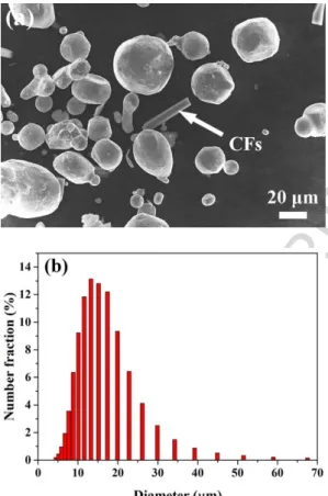
CFs added to the composite was 6 vol.%. The morphology of the composite powder
after milling and the distribution of raw powder were shown in Fig. 1. The equivalent
diameter of CFs was approximately 6 μm and its length was about 40 μm, which were
kept the same as for the raw CFs.
ACCEPTED MANUSCRIPT
The LASERTEL 8 kW high power semiconductor laser with a wavelength of 980
nm and the spot size of 12 mm×3 mm was used. Single tracks of the coating with a
thickness of 2 mm was deposited by the preplaced powder method. A shielding of
Argon gas was used to protect the molten pool. The schematic drawing of LC was
described in Fig. 2. The laser power was 3.2 kW and the laser scanning speeds used
were 2, 5, and 8 mm/s, respectively.
2.3 Microstructure characterization
After LC, the specimens were mechanically grounded, polished, and etched by a
solution of 90% alcohol (analytical reagent) and 10% HNO3 (analytical reagent). The
microstructure characteristics, fiber distribution and elements distribution of composite
coatings were analyzed by ZEISS Sigma 300 field emission scanning electron
microscopy (SEM) equipped with X-ray energy-dispersive spectrometer (EDS) at an
accelerating voltage of 20 kV. A D/MAX-2500 X-ray diffraction (XRD) machine was
used to analyze the phases of coatings (Cu target, 40 kV, 140 mA). Tecnai GF20 field
ACCEPTED MANUSCRIPT
morphology of CFs within coatings.
2.4 Properties evaluation
Microhardness distribution of composite coatings was measured by using a
HV-1000 Vickers digital microhardness tester with a load of 1.96 N and a dwell time of 15s.
To investigate the effect of laser scanning speed and CFs addition on the corrosion
resistance of composite coatings, the electrochemical resistance in 3.5 wt.% NaCl
solution was measured by the CHI604e electrochemical analyzer (Chenhua, Shanghai).
A three-electrode cell was used for the measurements, where a saturated calomel
electrode (SCE) was used as the reference electrode and a platinum foil (Pt) was used
as the counterpart. The specimens with an exposed area of about 1 cm2 as the working
electrode. All specimens were immersed in the test electrolyte at room temperature for
1 h to stabilize the open circuit potential (OCP). The potentiodynamic polarization
scanning was varied from ‒0.95 V to +0.2 V, and the sweep rate was 5 mV/s. The
corresponding corrosion current density (icorr) and corrosion potential (Ecorr) were
ACCEPTED MANUSCRIPT
spectroscopy (EIS) tests were performed at the OCP with an AC amplitude of 10 mV
in the frequency range from 105 Hz to 10-2 Hz.
Friction and wear experiments were conducted in air using a block-on-ring wear
test machine (M-2000) at room temperature. The size of the block was 12 mm×10
mm×10 mm, and the counterpart ring with 40 mm in outside diameter and 10 mm in
thickness was made of GCr15 bearing steel with the hardness of HRC 60±2. Meanwhile,
the tests were carried out under the dry sliding condition and the applied load was
maintained at 250 N. Moreover, three samples for each laser scanning speed were tested,
from which all the reported properties were averaged in this work. The ring was rotated
at 300 rpm for 8 h. After the wear tests, the debris and worn surfaces were analyzed by
SEM and EDS.
3. Results and discussion
3.1 Microstructure characteristics of composite coatings
Fig. 3 shows the XRD patterns for the Ni-based coating and CFs/Ni coatings. The
ACCEPTED MANUSCRIPT
M7C3, Fe4C0.63 and Ni3B, suggesting that laser scanning speed has no significant effect
on the phase constituent of the composite coatings.
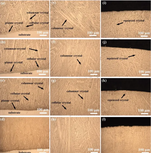
The microstructure of CFs/Ni and Ni-based coatings are shown in Fig. 4. It can be
seen that the microstructure characteristics of composite coatings from bonding zone
to the top coating are mainly planar crystal, cellular crystals, columnar dendrites and
equiaxed crystals. With increasing laser scanning speed, the thickness of planar crystal
is reduced from 17.2μm at 2 mm/s to 4.7μm at 5 mm/s (Figs. 4a~c), the columnar
dendrites present an elongated morphology and the secondary dendrites are refined
gradually. When laser scanning speed is further increased to 8 mm/s, the columnar
dendrites in bonding zone and central region are further reduced. However, the amount
of the refined cellular crystals is increased (Figs.4e~g), while the equiaxed crystals near
the top coating are refined (Figs.4i~k) from 17.7μm at 2 mm/s to 7.2μm at 8 mm/s.
However, when the processing parameters are constant, the CFs/Ni-based coatings
display much finer microstructure than Ni-based coatings (Figs. 4d, 4h and 4l), which
indicates that CFs are beneficial to refine grains.
ACCEPTED MANUSCRIPT
coatings is mainly dependent on the extent of constitutional undercooling, which is
closely related to the solidification velocity (R) and the temperature gradient (G). The
relationship can be expressed by the following equation: [24, 25]
2 0 2 (k T T) G P (1) cos s R V (2)
where T is the liquid temperature of the alloy, T0 is the initial temperature of the
substrate, is the absorption coefficient of the laser, P is the laser power, k is the
thermal conductivity of coating, Vs is the laser scanning speed, and is the angle
between Vs and R.
The primary dendrite arm spacing can be described as follows [26]:
a GR
(3)
where a is the coefficient. Manipulations of the Eqs. (1), (2) and (3) lead to the
following equation. 0 ( ) 2 scos a P T T kV (4)
In the melting zone of substrate, the temperature gradient G in front of the
ACCEPTED MANUSCRIPT
such, the molten metal near the bonding line is in the form of planar crystal and grows
up from the bottom of the molten pool. With increasing the distance from the bonding
line, the temperature gradient decreases. So, the solid/liquid interface of the planar
crystal becomes unstable when constitutional undercooling is greater than the front
solidification speed, resulting in that the planar crystal is transformed into the cellular
crystals and dendrites. At the bottom of molten pool, the growth of microstructure tends
to along the largest direction of thermal flux density. As a result, the growth of the
cellular crystals and dendrites near the bonding zone is perpendicular to the planar
crystal, because the heat is mainly transmitted from molten pool to the substrate during
LC. In the areas near the surface of molten pool, the growth of microstructure is
changed from columnar dendrites to equiaxed crystals, which is attributed to heat
transmission to the surrounding environment from multiple directions. With increasing
laser scanning speed, the solidification rate R increases therefore the ratio
𝐺/𝑅decreases. As a result, the morphology of microstructure is transformed from planar crystals to cellular crystals and dendrites rapidly. According to the Eq. (4), when
ACCEPTED MANUSCRIPT
are refined. Therefore, the thickness of the planar crystals decreases gradually. The
number of the dendrites is decreased and the refined cellular crystals are increased with
increasing laser scanning speed.
3.2 Characteristics of carbon fibers
Fig. 5 shows the distribution characteristics of CFs in the composite coatings
fabricated by LC. It can be seen that CFs are mainly distributed at grain boundaries.
Similar distribution characteristic of CFs was also reported in CFs/Mg composites by
powder metallurgy [27]. In addition, CFs are distributed more and more
homogeneously with increasing laser scanning speed, and the morphology of CFs
displays a more regular circle in the composite coatings when laser scanning speed is
increased to 8 mm/s. While laser scanning speed is only 2 mm/s, a large number of dark
particles are distributed along grain boundaries (Fig. 5a). According to the EDS analysis,
point A is composed of 35.8% C, 23.8% Fe, 34.5% Ni, 4.5% Cr and 1.4% Si (all in
wt.%), indicating these black particles are CFs that have been dissolved and interacted
ACCEPTED MANUSCRIPT
dark phases that distributed along grain boundaries are reduced, whereas the
cross-sectional morphology of CFs is deformed and displayed complex thin stripes, shown
as white arrows pointed (Fig. 5b). When laser scanning speed is further increased to 8
mm/s, little dark particles can be found along grain boundaries. The cross-sectional
morphology of CFs in the composite coatings are relatively regular, and the distribution
of CFs along the grain boundaries is homogenous. Moreover, there is no obvious
segregation between CFs (Fig. 5c). Fig. 5d shows the typical morphology of CFs with
lamellar structure, suggesting that the structure of CFs is basically well preserved. In
addition, no gaps or cracks can be found in the interface of carbon fiber and Ni-based
matrix. Fig. 6 shows the element distribution of the lineal energy spectrum. C element
is mainly distributed in the carbon fibers and little diffuses outward. But at the interface
of CF and matrix, elements such as Cr, Fe, Ni and Si are diffused into the carbon fiber
slightly, suggesting that CFs are kept the integrity of structure and a good interface
bonding when laser scanning speed is relatively higher.
It is well known that the center region of the laser beam with a Gaussian
ACCEPTED MANUSCRIPT
the radial direction on the surface of molten pool. Such a temperature gradient would
raise the surface tension gradient, thereby causing the materials near the surface of
molten pool flow from center to edges. As such, materials at the edge flow along the
solid line under the action of shearing force, then the melt flow encounters at the bottom
of the pool and rises to the surface, forming Marangoni convection [28]. Generally,
material transfer is mainly dependent on the convection in laser molten pool [29]. Under
the role of Marangoni convection, short CFs continue moving to the surface of molten
pool, so as to suffer from the high-energy laser beam ablation and destruction. When a
low laser scanning speed is adopted during LC, the solidification rate is low. Thus, the
time of CFs subjected to thermal damage of laser beam is longer, and most CFs are
burned during the floating process (Fig. 7a), thereby weakening the reinforcement
effect of CFs. When laser scanning speed is increased to 8 mm/s, the laser specific
energy is reduced and the solidification rate R increases. Thus, the time of CFs
subjected to laser beam is reduced during LC and the morphology of CFs remains
integrity (Fig. 7b). From thermodynamic point of view, the criterion for judging
ACCEPTED MANUSCRIPT
follows [30]: 1 Ni C K K (5) 1 2 1 Ni Ni Ni CCC C C K K (6)where KC and KNi are the thermal conductivity of carbon fiber and Ni, respectively; CC
and CNi are the specific heat capacity of carbon fiber and Ni, respectively; ρC and ρNi
represent the density of carbon fiber and Ni, respectively. When KC/KNi<1, single
carbon fiber plays a role in heat insulation at the solid-liquid interface. The solidified
interface behind carbon fiber forms a raised surface so that carbon fiber is expelled by
solid-liquid (S/L) interface due to the effect of interface curvature. On the contrary, if
KC/KNi>1, the trough that forms at the S/L interface will engulf the CFs. According to
the Eqs. (5), (6) and Table 3 [31], KC/KNi=0.16<1, (KCCCρC/KNiCNiρNi)1/2=0.22 <1, thus
CFs are expelled by solid-liquid interface during rapid solidification. Furthermore,
there exist many dislocations and vacancies around the grain boundaries of Ni-based
metallic matrix due to the structural stress caused by the volume shrinkage and phase
transformation after rapid solidification. The CFs tend to be distributed at these defects
ACCEPTED MANUSCRIPT
distributed homogeneously around grain boundaries. Due to Zener Pinning effect [32],
CFs increase the frictional resistance for the movement of grain boundaries, inhibit the
grain growth and finally result in grain refinement. Furthermore, with increasing laser
scanning speed, CFs that are distributed evenly along the grain boundaries with less
burned and deformed further play an effective role in suppressing grain growth.
3.3 Microhardness characteristics of composite coatings
Fig. 8 shows the microhardness distribution of composite coatings. It can be seen
from Fig. 8a that microhardness of CFs/Ni-based coating is approximately 1.3 times
higher than that of Ni-based coatings, indicating that CFs can evidently enhance the
microhardness of composite coatings. The average microhardness of CFs/Ni coatings
increases with an increase in laser scanning speed (Fig. 8b).
It can be seen from Fig. 8c that d-1/2 has a linear relationship with microhardness,
which suggests that the relationship between the microhardness and grain size (d)
satisfies the classical Hall-Petch equation [33-35]. With increasing laser scanning speed,
ACCEPTED MANUSCRIPT
the increased laser scanning speed improves the degree of grain refinement (Fig. 4),
which makes the grain boundaries much more than the original grain boundaries. As a
result, the external force that requires to produce the dislocation pile-up increases. So,
the microhardness of the coatings is enhanced.
3.4 Electrochemical performance of composite coatings
Fig. 9 shows the results of electrochemical experiments. It can be seen from the
anodic polarization curves (Fig. 9a) that all coatings have passivation regions,
indicating that the corrosion process has a passivation behavior. The lowest corrosion
current density of CFs/Ni coatings (1.66310-6 A/cm2) is 7% that of Ni-based coating
(2.35010-5 A/cm2). However, the lowest passivation current density of CFs/Ni
coatings (3.84410-6 A/cm2) is only 6 % that of Ni-based coating (6.49110-5 A/cm2)
and the highest polarization resistance of CFs/Ni coatings (25.350 kΩ/cm2) is about 4.4
times higher than that of Ni-based alloy coating (5.746kΩ/cm2) (Table 4), indicating
that CFs can improve the corrosion resistance of Ni-based coating. For CFs/Ni coatings,
the corrosion current densities icorr and the passivation current densities ipass show a
ACCEPTED MANUSCRIPT
resistances Rp increases, suggesting that the increase in laser scanning speed can
improve the electrochemical corrosion resistance of CFs/Ni coatings.
It can be seen from Nyquist plots (Fig. 9b) that the radii of the capacitive
impedance loops of CFs/Ni coatings are greater than that of Ni-based coating. Moreover,
the radii of the capacitive impedance loops of CFs/Ni coatings become greater with
increasing laser scanning speed. As well known, the larger the radius of the capacitive
impedance loop is, the better is the corrosion resistance [36]. Thus, CFs can largely
improve the corrosion resistance of composite coatings. Generally, the ability of
inhibiting the penetration of electrolyte in the composite coatings is related to the
middle frequency loop [37]. The larger the middle frequency loop is, the better is the
corrosion resistance. When laser scanning speed are 5 mm/s and 8 mm/s, the middle
frequency loops are obviously larger than the others in Bode curves (Fig. 9c), indicating
that the corrosion resistance of the two kinds of composite coatings are better than that
of the others. Moreover, the values of |Z|0.01Hz increase gradually (Fig. 9d) with an
increase in laser scanning speed, showing that the composite coatings can serve as more
ACCEPTED MANUSCRIPT
In conclusion, the EIS results further confirm that CFs can enhance the corrosion
resistance of Ni-based coatings, and the corrosion resistance of CFs/Ni coatings
increases with increasing laser scanning speed.
The electrochemical corrosion reactions of M (Ni, Cr) in 3.5 wt.% NaCl solution
at room temperature are as follows:
MMe(anodic reaction) (7)
2 2
2H OO 4e 4OH(cathodic reaction) (8)
The final products can be written as the following reactions:
MOH M(OH) (9)
2
M(OH)OH MOH O (10)
Then the passivation film is broken by Cl- within the electrolyte:
2 2
MO2ClH OMCl 2OH (11)
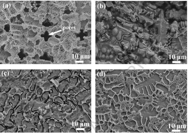
Fig. 10 shows the morphology of Ni-based coating and CFs/Ni coatings after
corrosion tests. The prominent corrosion occurs around the grain boundaries of γ-Ni
(Fig. 10a). It can be explained by the following reasons. Those C atoms adjacent to
ACCEPTED MANUSCRIPT
thereby decreasing the Cr content at boundaries and forming Cr-depleted regions at
grain boundaries [40]. As a result, the corrosion resistance of grain boundaries
decreases and the preferential corrosion takes place. Compared with C element, CFs
are chemical inertness and much more stable at high temperature [23]. Namely, C
element is easier to form carbides with alloying elements at high temperature. CFs are
distributed homogeneously along grain boundaries so that CFs can squeeze into the
positions of the defects at the grain boundaries, which can reduce segregation amount
of M7C3 and M23C6 carbides. Moreover, CFs have much better corrosion resistance than
the M7C3 and M23C6 carbides, which in turn can reduce the degree of corrosion. Hence,
the internal defects of the composite coatings are reduced and the density of the carbides
near grain boundaries is also decreased. Cr atoms in solid solution in grains are evenly
distributed around CFs, thereby improving the corrosion resistance near grain
boundaries. In addition, the refined grains have more grain boundaries, thereby
increasing the diffusion rate of Cr to form the passivation films rapidly so that the
corrosion process is inhibited [41]. For Ni-based coating without CFs, M7C3 and
ACCEPTED MANUSCRIPT
grain boundaries during electrochemical measurement. Therefore, grain boundaries and
grains tend to form smaller anode or greater cathode micro-batteries to accelerate the
intergranular corrosion [42]. For CFs/Ni coating, the potential difference between CFs
and grains near grain boundaries is decreased because the potential of CFs is much
higher than that of carbides [43]. As a result, the corrosion resistance of the composite
coatings is improved. However, when the laser scanning speed is only 2 mm/s, CFs
cannot maintain the original structure but they are seriously damaged and interact with
Ni-based matrix to form the carbides distributed at grain boundaries (Fig. 5a), resulting
in poor corrosion resistance. When the laser scanning speed is increased to 8 mm/s, the
structure of CFs is well kept and CFs are distributed homogeneously in Ni-based
coatings (Figs. 5c and 5d). In addition, the grain boundaries of Ni-based composite
coatings are much cleaner and few M7C3 and M23C6 carbides can be found in these
areas (Fig. 11). This indicates that CFs with few defects can decrease the amount of
M7C3 and M23C6 carbides at grain boundaries, so that the corrosion resistance of
ACCEPTED MANUSCRIPT
3.5 Wear properties of composite coatingsFig. 12 shows the results of friction and wear tests for Ni-based coating and CFs/Ni
coatings. Both the friction coefficient and wear rate decrease with increasing laser
scanning speed, as shown in Figs. 12a and 12b. Especially, when the laser scanning
speed is increased to 8 mm/s, the lowest wear rate of Ni-based composite coatings
(0.00208 mg/m) is just 55% of Ni-based coating (0.00375 mg/m). This indicates that
CFs can significantly reduce the friction coefficient and wear rate of Ni-based coating.
Thus, the wear resistance of composite coatings is improved.
Fig. 13 shows the morphology of the debris. According to the EDS analysis (Table
5), the contents of Fe and O are higher than other elements in the debris, suggesting
that the debris is mainly from the ring and is oxidized by air to form iron oxidation
during the friction process. In addition, there exist some Ni and Cr elements in the
debris. This is attributed to that Ni, Cr elements are easy to diffuse into the debris during
the friction process. Under the same processing parameters, the size of debris of CFs
reinforced base composite coatings is smaller (1.14μm) compared with that of
ACCEPTED MANUSCRIPT
coatings is refined gradually with an increase in laser scanning speed (Figs.13b~13d).
Fig. 14 shows the morphology of the worn surface after dry sliding wear. The wear
degree for the composite coatings is significantly lower than that of Ni-based coating
without CFs reinforcement (Figs. 14a and 14d). As shown in Figs.14a and 14b, the
debris is pushed into the spalling pits and evident phenomenon for material transfer is
observed on the surface of coating, indicating that adhesive wear behavior occurs
during the wear process. Some dark and sheet-like materials on the worn surfaces of
the coatings (such as point E, F) are observed in Figs. 14b and 14c, which are mainly
iron oxidation according to the EDS analysis (Table 5). With increasing the laser
scanning speed, the adhesive materials on the worn surface are reduced and the spalling
pits are also reduced, showing that the wear resistance of the composite coatings is
relatively better (Figs. 14b~14d).
In the initial stage of the dry sliding wear, the ring is firstly contacted with bonding
metal which is relatively soft. As a result, the adhesive wear takes place. With
proceeding of the wear process, some debris falls from the surfaces of ring and coating
ACCEPTED MANUSCRIPT
resulting in plastic deformation and features of plowing grooves. This indicates that the
abrasive wear has taken place. On one hand, during the dry sliding wear, the friction
force acting on the surface of coating causes the plastic deformation of subsurface,
which keeps on accumulating with repeated load. When the plastic deformation reaches
a certain degree, the cracks nucleation occurs in the subsurface and continues
propagating to the surface. On the other hand, the friction heat causes the temperature
rising, so that the contact surface between ring and coating becomes relatively soft. The
abrasive wear aggravates on the friction surface. Thus, the debris on the friction surface
increases, which forms more obviously micro-cutting. Due to the micro-cutting of
abrasive particles and crack propagation, the fragments are peeled off from the surface
of coating (Fig. 13b).
For CFs/Ni coatings, CFs have good self-lubricate property and are in the form
of graphite particles or segments which pressed and adhered to the surface of the
composite coatings to form a lubricating layer during dry sliding wear [44]. The
lubricating layer can reduce the direct contact between ring and composite coating, so
ACCEPTED MANUSCRIPT
Due to the thermal conductivity of GCr15 (36.92 W/(K·m)) is relatively poor compared
with the composite coatings, the hardness of the surface of GCr15 decreases sharply.
Therefore, the materials on the surface of the ring begin to transfer to the surface of the
composite coating. However, the materials that transferred from the ring took place
plastic deformation after a number of repeated rolling, so that ultimately many dark and
sheet-like materials are formed on the surface of the composite coating. When the laser
scanning speed is low, a lot of CFs suffer from dissolution and heat damage, M7C3 and
M23C6 carbides precipitated in the composite coating are increased (Fig. 5a). As a result,
the abrasive particles increase during dry sliding wear, so that the micro-cutting is
obvious. In addition, the cracks are easy to propagate because the precipitated carbides
in the coating can increase the brittleness of the coating, resulting in large debris peeled
off from the surface. With increasing laser scanning speed, the degree of dissolution
and heat damage of CFs decreases, so the content of the precipitated carbides decreases,
and the surface of the composite coating mainly suffers from the abrasive wear. Because
many CFs are not dissolved completely, so that they can prevent the wear from further
ACCEPTED MANUSCRIPT
coating are decreased. When the laser scanning speed is higher, CFs are distributed
more homogeneously and shapes are more regular than those in other coatings. Thus, a
uniform and good lubricating layer is formed constantly during dry sliding wear, and
the wear mechanism of surface is dominated by abrasive wear. Furthermore, the
microhardness of the composite coating is the highest so that the abrasive particles are
not easy to pierce into the surface to cause micro-cutting, therefore the wear resistance
of the composite coating is improved.
CFs with good combination of interfaces can effectively transmit the load from
friction surface to Ni-based matrix, which can enhance the resistance to plastic
deformation of the subsurface [46]. This is also the main reason why peeling does not
occur when laser scanning speed are 5 mm/s and 8 mm/s. In other words, CFs can
effectively inhibit the propagation of the cracks and improve the strength of the
composite coating as well as the resistance to plastic deformation of the subsurface. As
a result, the wear resistance of CFs/Ni coating is improved.
ACCEPTED MANUSCRIPT
Generally, the composite coatings fabricated by laser cladding are vulnerable to
crack due to the residual stress in the coatings. The residual stress is composed of the
contraction stress vol and the thermal stress T. The thermal stress can be explained
as follows [47]: c s s c s T s s c c E E t ( ) T = (1 V)(E t E t ) (12) where Ec and Es are elastic modulus of the coating and the substrate, respectively; tc
and ts are the height of the coating and substrate, respectively;c ands are the
coefficient of thermal expansion (CTE) of the coating and substrate, respectively; V
represents Poisson ratio; andTis the difference between the solidification temperature
of the molten cladding material and the room temperature. Zhou [48] et. al studied the
residual stress of Ni-based WC composite coatings fabricated by LC. It is found that
crack sensitivity increases with increasing laser scanning speed. However, in this work,
with increasing laser scanning speed, there is no apparent micro-cracks in CFs/Ni-based
coatings. The reasons are discussed in the following. When the temperature of
composite coating gradually recovers to room temperature, metal in the matrix shrinks
ACCEPTED MANUSCRIPT
(about -0.74×10⁻⁶ K-1 in axial direction), CFs would expand instead. When laser
scanning speed is high, CFs are distributed uniformly and with good morphology in the
coating as well as good interfacial bonding, which can impel the expansive CFs to
restrict the metal contracting. As a result, the convection stress is significantly reduced.
Also, a better interfacial bonding between CFs and the matrix can lead to a stronger
physical confinement thereby lowering the CTE of the composite [49]. According to
Eq. (12), the thermal stressTmay reduce because of the reduction in CTE of the
coating (c ). Besides, with increasing the laser scanning speed, many columnar
crystals transform into refined cellular crystals and equiaxed crystals, as discussed in
Section 3.1. The fine equiaxed crystals can be easily to realize the coordinated
deformation between the grains, so that these fine equiaxed crystals can well adjust the
convection stress [50].
To sum up the discussion above, with increasing laser scanning speed, because of
negative CTE of CFs and finer equiaxed crystals as well as good interfacial bonding,
the convection stress and thermal stress of CFs/Ni-based coating may be reduced.
ACCEPTED MANUSCRIPT
LC are free of cracks. The further experiments and discussions will be reported in the
near future.
4. Conclusions
In the present work, CFs/Ni-based coatings are successfully fabricated by LC
without prominent micro-cracks. It is found that CFs and laser scanning speed have an
important positive influence on the microstructure characteristics and performances of
the composite coatings. With an increase in laser scanning speed, CFs dispersion and
morphology are better than those at low laser scanning speed. So the refinement of
grains is more apparent, thereby enhancing the properties of the composite coating. The
main conclusions are drawn as follows.
1.When laser scanning speed is 8 mm/s, the CFs/Ni-based composite coating has a
refined microstructure and good dispersion of CFs in the microstructure. As such, the
CFs/Ni-based composite coating exhibit high performance in terms of microhardness,
corrosion resistance and wear resistance.
ACCEPTED MANUSCRIPT
relatively higher. With increasing the laser scanning speed, the corrosion resistance of
CFs/Ni-based coatings gradually increases due to high corrosion resistance of CFs and
decrease in the amount of precipitated M7C3 and M23C6 carbides adjacent to grain
boundaries.
3. CFs/Ni-based coatings show better wear resistance than Ni-based alloy coatings.
With an increase in laser scanning speed, the wear resistance of the composite coatings
gradually increases, which can be attributed to good self-lubrication property and good
dispersion of CFs in the coatings.
Acknowledgments
This work was financially supported by the National Natural Science Foundation
of China (Grant No. 61475117, 51471084), Applied Basic Research and Development
Project of Tianjin City (Grant No.12JCQNJC02800), the Key Technology R & D
Program of Tianjin City (Grant No. 13ZCZDGX01109), the Foundation of Civil
Aviation University of China (Grant No. 2014TJPUJG), the Science and Development
ACCEPTED MANUSCRIPT
the Outstanding Youth Foundation of Jiangxi Province (Grant No.20162BCB23039).
References
[1] J. Xu, L. Zhao, X. Deng, H. Yu, High temperature simulation of short carbon
fiber-reinforced nickel base composite, Materials & Design 27(10) (2006) 1152-1156.
[2] N. Elkhoshkhany, A. Hafnway, A. Khaled, Electrodeposition and corrosion
behavior of nano-structured Ni-WC and Ni-Co-WC composite coating, Journal of
Alloys and Compounds 695 (2017) 1505-1514.
[3] A. Chaudhuri, Y. Raghupathy, D. Srinivasan, S. Suwas, C. Srivastava,
Microstructural evolution of cold-sprayed Inconel 625 superalloy coatings on low alloy
steel substrate, Acta Materialia 129 (2017) 11-25.
[4] G. Bolelli, A. Candeli, L. Lusvarghi, T. Manfredini, A. Denoirjean, S. Valette, A.
Ravaux, E. Meillot, “Hybrid” plasma spraying of NiCrAlY+Al2O3+h-BN composite
coatings for sliding wear applications, Wear 378-379 (2017) 68-81.
[5] L. He, Y. Tan, X. Wang, T. Xu, X. Hong, Microstructure and wear properties of
Al2O3-CeO2/Ni-base alloy composite coatings on aluminum alloys by plasma spray,
ACCEPTED MANUSCRIPT
[6] J.J. Tian, S.W. Yao, X.T. Luo, C.X. Li, C.J. Li, An effective approach for creating
metallurgical self-bonding in plasma-spraying of NiCr-Mo coating by designing
shell-core-structured powders, Acta Materialia 110 (2016) 19-30.
[7] M. Jafari, M.H. Enayati, M. Salehi, S.M. Nahvi, C.G. Park, Microstructural and
mechanical characterizations of a novel HVOF-sprayed WC-Co coating deposited from
electroless Ni–P coated WC-12Co powders, Materials Science and Engineering: A 578
(2013) 46-53.
[8] Y.J. Liu, H.L. Wang, S.J. Li, S.G. Wang, W.J. Wang, W.T. Hou, Y.L. Hao, R. Yang,
L.C. Zhang, Compressive and fatigue behavior of beta-type titanium porous structures
fabricated by electron beam melting, Acta Materialia 126 (2017) 58-66.
[9] Y. Chen, F. Lu, K. Zhang, P. Nie, S.R. Elmi Hosseini, K. Feng, Z. Li, Laser powder
deposition of carbon nanotube reinforced nickel-based superalloy Inconel 718, Carbon
107 (2016) 361-370.
[10] D.D. Gu, W. Meiners, K. Wissenbach, R. Poprawe, Laser additive manufacturing
of metallic components: materials, processes and mechanisms, International Materials
ACCEPTED MANUSCRIPT
[11] L.C. Zhang, H. Attar, Selective Laser Melting of Titanium Alloys and Titanium
Matrix Composites for Biomedical Applications: A Review, Advanced Engineering
Materials 18 (2016) 463-475.
[12] C.Y. Yap, C.K. Chua, Z.L. Dong, Z.H. Liu, D.Q. Zhang, L.E. Loh, S.L. Sing,
Review of selective laser melting: Materials and applications, Applied Physics Reviews
2(4) (2015) 041101.
[13] M.M. Quazi, M.A. Fazal, A.S.M.A. Haseeb, F. Yusof, H.H. Masjuki, A. Arslan,
Effect of rare earth elements and their oxides on tribo-mechanical performance of laser
claddings: A review, Journal of Rare Earths 34(6) (2016) 549-564.
[14] Y. Cai, Z. Luo, M. Feng, Z. Liu, Z. Huang, Y. Zeng, The effect of TiC/Al2O3
composite ceramic reinforcement on tribological behavior of laser cladding Ni60 alloys
coatings, Surface and Coatings Technology 291 (2016) 222-229.
[15] X. Luo, J. Li, G.J. Li, Effect of NiCrBSi content on microstructural evolution,
cracking susceptibility and wear behaviors of laser cladding WC/Ni–NiCrBSi
composite coatings, Journal of Alloys and Compounds 626 (2015) 102-111.
ACCEPTED MANUSCRIPT
layer and machining vibration suppressing in side milling, Applied Surface Science 321
(2014) 387-395.
[17] Y. Huang, X. Zeng, Q. Hu, S. Zhou, Microstructure and interface interaction in
laser induction hybrid cladding of Ni-based coating, Applied Surface Science 255(7)
(2009) 3940-3945.
[18] D. Lin, C. Richard Liu, G.J. Cheng, Single-layer graphene oxide reinforced metal
matrix composites by laser sintering: Microstructure and mechanical property
enhancement, Acta Materialia 80 (2014) 183-193.
[19] J.Y. Hwang, A. Neira, T.W. Scharf, J. Tiley, R. Banerjee, Laser-deposited carbon
nanotube reinforced nickel matrix composites, Scripta Materialia 59(5) (2008) 487-490.
[20] S. Zhou, C. Wu, T. Zhang, Z. Zhang, Carbon nanotube- and Fep-reinforced
copper–matrix composites by laser induction hybrid rapid cladding, Scripta Materialia
76 (2014) 25-28.
[21] S. Suárez, E. Ramos-Moore, B. Lechthaler, F. Mücklich, Grain growth analysis of
multiwalled carbon nanotube-reinforced bulk Ni composites, Carbon 70 (2014)
ACCEPTED MANUSCRIPT
[22] K. Shirvanimoghaddam, S.U. Hamim, M. Karbalaei Akbari, S.M. Fakhrhoseini,
H. Khayyam, A.H. Pakseresht, E. Ghasali, M. Zabet, K.S. Munir, S. Jia, J.P. Davim, M.
Naebe, Carbon fiber reinforced metal matrix composites: Fabrication processes and
properties, Composites Part A: Applied Science and Manufacturing 92 (2017) 70-96.
[23] A. Khoddamzadeh, R. Liu, M. Liang, Q. Yang, Wear resistant carbon fiber
reinforced Stellite alloy composites, Materials & Design (1980-2015) 56 (2014)
487-494.
[24] S. Zhou, Y. Huang, X. Zeng, Q. Hu, Microstructure characteristics of Ni-based
WC composite coatings by laser induction hybrid rapid cladding, Materials Science and
Engineering: A 480(1-2) (2008) 564-572.
[25] M. Zhong, W. Liu, K. Yao, J.-C. Goussain, C. Mayer, A. Becker, Microstructural
evolution in high power laser cladding of Stellite 6+WC layers, Surface and Coatings
Technology 157(2-3) (2002) 128-137.
[26] Y. Huang, X. Zeng, Q. Hu, S. Zhou, Microstructure and interface interaction in
laser induction hybrid cladding of Ni-based coating, Applied Surface Science 255(7)
ACCEPTED MANUSCRIPT
[27] L.G. Hou, R.Z. Wu, X.D. Wang, J.H. Zhang, M.L. Zhang, A.P. Dong, B.D. Sun,
Microstructure, mechanical properties and thermal conductivity of the short carbon
fiber reinforced magnesium matrix composites, Journal of Alloys and Compounds 695
(2017) 2820-2826.
[28] B. Ma, J. Li, Z. Peng, G. Zhang, Structural morphologies of Cu–Sn–Bi immiscible
alloys with varied compositions, Journal of Alloys and Compounds 535 (2012) 95-101.
[29] T.R. Anthony, H.E. Cline, Surface rippling induced by surface‐tension gradients
during laser surface melting and alloying, Journal of Applied Physics 48(9) (1977)
3888-3894.
[30] D.Stefanescu, Solidification of Metal Matrix Composites. In: Science and
Engineering of Casting Solidification. Springer, Cham, 2015.
[31] Y. Liu, S. Kumar, Recent Progress in Fabrication, Structure, and Properties of
Carbon Fibers, Polymer Reviews 52(3) (2012) 234-258.
[32] P.A. Manohar, M. Ferry, T. Chandra, Five Decades of the Zener Equation, ISIJ
International 38(9) (1998) 913-924.
ACCEPTED MANUSCRIPT
composites: Influence of the microstructural refinement on the hardness, Materials
Science and Engineering: A 587 (2013) 381-386.
[34] L. Liu, W. Li, Y. Tang, B. Shen, W. Hu, Friction and wear properties of short carbon
fiber reinforced aluminum matrix composites, Wear 266(7-8) (2009) 733-738.
[35] C.R. Carpenter, P.H. Shipway, Y. Zhu, The influence of CNT co-deposition on
electrodeposit grain size and hardness, Surface and Coatings Technology 205(21-22)
(2011) 5059-5063.
[36] J.Z. Lu, B. Han, C.Y. Cui, C.J. Li, K.Y. Luo, Electrochemical and pitting corrosion
resistance of AISI 4145 steel subjected to massive laser shock peening treatment with
different coverage layers, Optics & Laser Technology 88 (2017) 250-262.
[37] N. Dai, L.-C. Zhang, J. Zhang, X. Zhang, Q. Ni, Y. Chen, M. Wu, C. Yang,
Distinction in corrosion resistance of selective laser melted Ti-6Al-4V alloy on
different planes, Corrosion Science 111 (2016) 703-710.
[38] Z.H. Wen, Y. Bai, J.F. Yang, J. Huang, Corrosion resistance of vacuum re-melted
Ni60-NiCrMoY alloy coatings, Journal of Alloys and Compounds 711 (2017) 659-669.
ACCEPTED MANUSCRIPT
laser melted Ti-6Al-4V alloy in NaCl solution, Corrosion Science 102 (2016) 484-489.
[40] Y. Yin, R.G. Faulkner, P. Moreton, I. Armson, P. Coyle, Grain boundary chromium
depletion in austenitic alloys, Journal of Materials Science 45(21) (2010) 5872-5882.
[41] L. Liu, Y. Li, F. Wang, Influence of grain size on the corrosion behavior of a
Ni-based superalloy nanocrystalline coating in NaCl acidic solution, Electrochimica Acta
53(5) (2008) 2453-2462.
[42] J. Qian, C. Chen, H. Yu, F. Liu, H. Yang, Z. Zhang, The influence and the
mechanism of the precipitate/austenite interfacial C-enrichment on the intergranular
corrosion sensitivity in 310 S stainless steel, Corrosion Science 111 (2016) 352-361.
[43] Y. Pan, G. Wu, Z. Huang, X. Wu, Y. Liu, H. Ye, Corrosion behaviour of carbon
fibre reinforced polymer/magnesium alloy hybrid laminates, Corrosion Science 115
(2017) 152-158.
[44] D. Jun, L. Yao-hui, Y. Si-rong, L. Wen-fang, Dry sliding friction and wear
properties of Al2O3 and carbon short fibres reinforced Al–12Si alloy hybrid
composites, Wear 257(9-10) (2004) 930-940.
ACCEPTED MANUSCRIPT
matrix composites reinforced with short carbon fibers, Materials & Design 29(1) (2008)
257-261.
[46] G. Garces, G. Bruno, A. Wanner, Load transfer in short fibre reinforced metal
matrix composites, Acta Materialia 55(16) (2007) 5389-5400.
[47] P.B. Kadolkar, T.R. Watkins, J.T.M. De Hosson, B.J. Kooi, N.B. Dahotre, State of
residual stress in laser-deposited ceramic composite coatings on aluminum alloys, Acta
Materialia 55(4) (2007) 1203-1214.
[48] S. Zhou, X. Zeng, Q. Hu, Y. Huang, Analysis of crack behavior for Ni-based WC
composite coatings by laser cladding and crack-free realization, Applied Surface
Science 255(5) (2008) 1646-1653.
[49] F. Li, C.-B. Qu, Y. Hua, H.-M. Xiao, S.-Y. Fu, Largely improved dimensional
stability of short carbon fiber reinforced polyethersulfone composites by graphene
oxide coating at a low content, Carbon 119 (2017) 339-349.
[50] Kou, Sindo. Welding Metallurgy, Second Edition (2003) 253-280.
ACCEPTED MANUSCRIPT
Figure captionsFig. 1. (a) morphology of the composite powder and (b) the diameter distribution of the
raw Ni-based powder.
Fig. 2. Schematic drawing of LC process
Fig. 3. XRD pattern in the 2θrange from 20°to 110°for Ni-based coating (A with laser
scanning speed of 8 mm/s) and CFs/Ni coatings (B, C, D with laser scanning speed of
2 mm/s, 5 mm/s and 8 mm/s, respectively).
Fig. 4. The optical microscopy image of coatings. (a), (b) and (c) bonding zones, (e),
(f) and (g) centre zones, and (i), (j) and (k) areas near top coating of the composite
coating with laser beam scanning speed of 2 mm/s, 5 mm/s, 8 mm/s, respectively. (d),
(h) and (l) microstructure of Ni-based alloy coating with laser scanning speed of 8 mm/s.
(across-sections are made longitudinal to the laser beam scanning direction).
Fig. 5. High-magnified morphology of carbon fiber with laser scanning speed of (a) 2
mm/s and (b) 5 mm/s and (c) 8 mm/s, and (d) magnified morphology of B indicated in
(c).
ACCEPTED MANUSCRIPT
scanning speed of 8 mm/s.
Fig. 7. TEM morphology of CFs distributed in coatings at laser scanning speed of (a) 2
mm/s and (b) 8 mm/s.
Fig. 8. (a) Microhardness of Ni-based coating and CFs/Ni-based coatings with laser
scanning speed of 8 mm/s, and (b) the average microhardness of the composite coatings
with different laser scanning speed, and (c) the relationship between the grain size d
and the microhardness.
Fig. 9. The curves of electrochemical tests. (a) anodic polarization curves and (b)
Nyquist plots and (c), (d) Bode plots.
Fig. 10. Morphology of the surface after electrochemical corrosion at 0.5 V for 20 min.
(a) Ni-based coating with laser beam scanning speed of 8 mm/s and the composite
coatings with laser beam scanning speed of (b) 2 mm/s, (c) 5 mm/s, and (d) 8 mm/s.
Fig. 11. High-magnified SEM image of the composite coating with laser scanning speed
of 8 mm/s after corrosion.
Fig. 12. (a) friction coefficient and (b) wear rate of Ni-based coating and the composite
ACCEPTED MANUSCRIPT
Fig. 13. Morphology of the debris of (a) Ni-based coating with laser scanning speed of
8 mm/s and of the composite coatings with laser scanning speed of (b) 2 mm/s, (c) 5
mm/s, and (d) 8 mm/s.
Fig. 14. Morphology of the worn surface after the friction experiments. (a) surface of
Ni-based coating with laser scanning speed of 8 mm/s and worn surfaces of the
composite coatings with laser scanning speed of (b) 2 mm/s, (c) 5 mm/s, and (d) 8 mm/s.
Table captions
Table 1 Chemical composition of 1Cr13 substrate in wt.%.
Table 2 Chemical composition of Ni25 powder in wt.%.
Table 3 The physical properties of carbon fiber and nickel.
Table 4 Electrochemical parameters obtained from polarization curves of Ni-based
alloy coating and the composite coatings.
ACCEPTED MANUSCRIPT
Fig. 1. (a) morphology of the composite powder and (b) the diameter distribution of the raw Ni-based
ACCEPTED MANUSCRIPT
ACCEPTED MANUSCRIPT
Fig. 3. XRD patterns in the 2θ range from 20° to 110° for Ni-based coating (A, with laser scanning
speed of 8 mm/s) and CFs/Ni coatings (B, C, D with laser scanning speed of 2, 5, and 8 mm/s,
ACCEPTED MANUSCRIPT
Fig. 4. The optical microscopy image of coatings: (a), (b) and (c) bonding zones, (e), (f) and (g) centre
zones, and (i), (j) and (k) areas near top coating of the composite coating with laser scanning speed of 2
mm/s, 5 mm/s, 8 mm/s, respectively. (d), (h) and (l) microstructure of Ni-based alloy coating with laser
ACCEPTED MANUSCRIPT
Fig. 5. High-magnified morphology of carbon fiber with laser scanning speed of (a) 2 mm/s, (b) 5 mm/s
ACCEPTED MANUSCRIPT
Fig. 6. EDS spectrum for the LMD-produced CFs/Ni-based composite coating at laser scanning speed
ACCEPTED MANUSCRIPT
Fig. 7. TEM morphology of CFs distributed in coatings at laser scanning speed of (a) 2 mm/s and (b) 8
ACCEPTED MANUSCRIPT
Fig. 8. (a) Microhardness of Ni-based coating and CFs/Ni-based coatings with laser scanning speed of
8mm/s, and (b) the average microhardness of the composite coatings with different laser scanning speed,
ACCEPTED MANUSCRIPT
Fig. 9. The curves of electrochemical tests. (a) anodic polarization curves and (b) Nyquist plots and (c),
ACCEPTED MANUSCRIPT
Fig. 10. Morphology of the surface after electrochemical corrosion at 0.5 V for 20 min. (a) Ni-based
coating with laser scanning speed of 8 mm/s and the composite coatings with laser scanning speed of (b)
ACCEPTED MANUSCRIPT
Fig. 11. High-magnified SEM image of the composite coating with laser scanning speed of 8 mm/s after
ACCEPTED MANUSCRIPT
Fig. 12. (a) Friction coefficient and (b) wear rate of Ni-based coating and the composite coatings with
ACCEPTED MANUSCRIPT
Fig. 13. Morphology of the debris of (a) Ni-based coating with laser scanning speed of 8 mm/s and of
ACCEPTED MANUSCRIPT
Fig. 14. Morphology of the worn surface after the friction experiments. (a) surface of Ni-based coating
with laser scanning speed of 8 mm/s and worn surfaces of the composite coatings with laser scanning
ACCEPTED MANUSCRIPT
Tables
Table 1 Chemical composition of 1Cr13 substrate in wt.%.
Element C Mn P S Si Cr Ni Fe
Mass
fraction
ACCEPTED MANUSCRIPT
Table 2 Chemical composition of Ni25 powder in wt.%.
Element C Cr B Si Fe Ni
Mass
fraction
ACCEPTED MANUSCRIPT
Table 3 The physical properties of carbon fiber and nickel.
Samples g/cm3 K W/(K·m) C kJ/(kg·K) C fiber 1.76 14 0.712 Ni 8.9 88.9 0.45
ACCEPTED MANUSCRIPT
Table 4 Electrochemical parameters obtained from polarization curves of Ni-based coating and the
composite coatings. Samples Ecorr (V) Icorr (A/cm2) Rp (ohm) Epass (V) Ipass (A/cm2)
0 vol.% CFs 8mm/s -0.806 2.350E-5 5745.7 -0.766 6.491E-5
6 vol.% CFs
2mm/s -0.790 1.406E-5 9688.8 -0.725 4.702E-5
5mm/s -0.675 3.789E-6 11141.7 -0.648 5.852E-6
ACCEPTED MANUSCRIPT
Table 5 EDS analysis of the elements at different points in Fig. 13 and Fig. 14 (wt. %).
Point No. C O Si Cr Fe Ni
C 8.79 39.4 0.39 4.85 41.88 4.7
D 7.32 33.12 0.71 5.20 43.82 9.84
E 5.1 29.6 0.44 7.11 52.10 5.65
ACCEPTED MANUSCRIPT
Highlights
1. Carbon fibers reinforced Ni-based composite coatings are fabricated by laser
cladding.
2. Increasing laser scanning speed can improve the morphology and distribution of
carbon fibers.
3. Carbon fibers can enhance the corrosion resistance and wear resistance of
CFs/Ni-based coatings compared with Ni-CFs/Ni-based coating.
4. Corrosion and wear resistance of CFs/Ni-based coatings are further improved with