Tropos Networks, Inc. 555 Del Rey Avenue Sunnyvale, CA 94085
Tropos Networks User Guide
Release 5.1
Tropos Networks User Guide ii Copyright 2005 by Tropos Networks
All rights reserved. Rights reserved under the copyright laws of the United States. RESTRICTED RIGHTS LEGEND
Use, duplication, or disclosure by the United States Government is subject to restrictions as set forth in subparagraph (c)(1)(II) of the Rights in Technical Data and Computer Software clause at DFARS 252.227-7013.
Notwithstanding any other license agreement that may pertain to, or accompany the delivery of, this computer software, the rights of the United States Government regarding its use, reproduction, and disclosure are as set forth in the Commercial Computer Software-Restricted Rights clause at FAR52.227-19.
IMPORTANT NOTE TO USERS
This software is provided by Tropos Networks, Inc. as is and any express or implied warranties, including, but not limited to, implied warranties of merchantability and fitness for a particular purpose are disclaimed. In no event shall Tropos Networks, or its affiliates, subsidiaries or suppliers be liable for any direct, indirect, incidental, special, exemplary, or consequential damages (including, but not limited to, procurement of substitute goods or services; loss of use, data or profits; or business interruption) however caused and on any theory of liability, whether in contract, strict liability, or tort (including negligence or otherwise) arising in any way out of the use of this software, even if advised of the possibility of such damage.
Tropos reserves the right to make changes without further notice to any products herein.
FCC Notice to Users and Operators
Tropos MetroMesh routers comply with Part 15 of the FCC rules. Operation of the Tropos MetroMesh router is subject to the following two conditions:
1. This device may not cause harmful interference, and
2. This device must accept any interference received, including interference that may cause undesired operation.
This equipment has been tested and found to comply with the limits of a Class A digital device, pursuant to Part 15 of the FCC Rules. These limits are designed to provide reasonable protection against harmful interference when the equipment is operated in an office environment. This equipment generates, uses and radiates radio frequency energy, and if not installed and used in accordance with the instructions, the device may cause harmful interference. However, there is no guarantee that interference will not occur. If this equipment does cause interference to radio or television reception, which can be determined by turning the equipment off and on, the user is encouraged to correct the interference by using one of the following measures:
Reorient or relocate the receiving antenna.
Increase separation between the equipment and receiver.
Connect the equipment to an outlet on a circuit different from that to which the receiver is connected.
This Part 15 radio device operates on a non-interference basis with other devices operating at this frequency. Any changes or modification to said product not expressly approved by Tropos Networks could void the user's authority to operate this device.
Tropos Networks User Guide iii
Contents
Preface . . . vi 1 Overview . . . 1 Product Overview . . . 1 Product Features . . . 1Tropos Networks Architecture . . . 2
Tropos Mobile MetroMesh Networks . . . 4
Tropos Network Management and Administration . . . 7
2 Getting Started . . . 8
Setting Up a New Wireless Network . . . 8
Setting the Gateway Configuration. . . 9
Using the Configuration Utility . . . 13
Top Information Bar. . . 14
Committing Changes. . . 14
Adding Fixed Nodes to the Network. . . 15
Adding Mobile Nodes to the Network . . . 17
Adding Clients to the Network . . . 20
Reassigning Gateways and Nodes . . . 24
Confirming Router Identity. . . 25
Checking the Current Configuration . . . 26
Accessing the Configuration Utility Through a Wireless Connection . . . . 27
Setting the Time . . . 28
3 Configuring Wireless Settings . . . 30
Service Sets . . . 30
Transmission Rates and Channels . . . 31
Automatic Channel Selection . . . 31
Security . . . 32
Router-to-Router Security . . . 34
Beacon Rates. . . 35
Roaming . . . 35
Multiple ESSIDs . . . 35
Power Levels and Transmit Antenna Diversity. . . 36
Setting the Wireless Configuration . . . 37
Configuring Multiple ESSIDs . . . 39
4 Configuring Network Settings . . . 41
Overview . . . 41
Configuring DHCP Settings . . . 43
Configuring a Single DHCP server . . . 45
Configuring Multiple Redundant DHCP servers . . . 50
Relaying DHCP Requests to an External Server . . . 52
Configuring Networks with Mobile Nodes. . . 52
Configuring Network Address Translation . . . 53
Configuring Dual Subnet Support. . . 55
Dual Subnets and DHCP Relay . . . 56
Configuring Wired Ports . . . 57
Ethernet Speed and Duplex . . . 57
Wired Interface (MTU). . . 58
Downstream Sub-Interface . . . 58
Supporting Layer 2 Emulation . . . 62
Configuring Uplink Check. . . 64
Configuring Power Sourcing for Power Over Ethernet. . . 65
Configuring a Service Gateway . . . 66
5 Managing Clients . . . 70
Supporting Multi-Subnet Roaming . . . 70
Configuring DHCP MAC Address Filters and Address Reservations. . . 74
Client Access . . . 78
Supporting Static IP Clients . . . 81
Static Client for Mobile Node. . . 83
Defining Packet Filter Forwarding Rules . . . 83
NTP Session Example . . . 88
Packet Hit Counts . . . 89
Configuring VLANs. . . 89
Management VLAN . . . 90
ESSID-Based VLANs . . . 90
IP-based VLANs . . . 91
Client DHCP Relay Policy . . . 93
Multi-Subnet Roaming with VLANs . . . 93
Tropos Networks User Guide v
VLAN Configuration Steps . . . 95
Configuring Quality of Service . . . 100
Bandwidth Reservations . . . 100
Priority Based Forwarding . . . 101
Classification Rules . . . 102
Configuring Rate Limits . . . 105
6 Maintaining the Network . . . 108
Viewing Equipment Status . . . 109
Tropos 5210, 4210, and 5110 Routers . . . 109
Operational Lights on Indoor Tropos Routers . . . 111
Viewing Current Configuration Settings . . . 112
Restarting the Tropos Router . . . 113
Managing Router Access . . . 114
Restoring the Default Password . . . 116
Updating Software . . . 116
Managing Configuration Profiles . . . 118
Configuring SNMP and Trap Settings . . . 120
Generating SSL Certificates. . . 124
Viewing Event Logs . . . 125
Glossary . . . 128
Preface
This guide contains the information and instructions required to install, configure and maintain Tropos MetroMesh routers using the Tropos Configuration Utility. It is intended for use by network engineers and administrators who are responsible for setting up and administering Tropos wireless networks. Some familiarly with local area networking and wireless networking concepts is assumed.
This guide contains the following chapters:
Chapter 1, “Overview,” introduces the features of the Tropos MetroMesh router and provides an overview of the Tropos Networks wireless network architecture.
Chapter 2, “Getting Started,” provides information and instructions for setting up Tropos MetroMesh routers to create a wireless network.
Chapter 3, “Configuring Wireless Settings,” describes the parameters available to control RF communications in the Tropos MetroMesh router network.
Chapter 4, “Configuring Network Settings,” describes the configuration options available to implement a variety of wireless network topologies.
Chapter 5, “Managing Clients,” describes the configuration options available to provide services to network clients.
Chapter 6, “Maintaining the Network,” contains information on how to keep the Tropos MetroMesh routers working effectively.
Tropos Networks User Guide vii
Tropos Technical Support
For technical assistance, contact the Tropos Technical Assistance Center.
Supporting Documentation
The following documents are available on the installation CD or shipped with Tropos Networks equipment.
Release Notes — Contains information specific to the current product release.
Quick Start Guide — Contains instructions on installing and configuring a Tropos wireless network quickly and easily.
Tropos Networks Configuration Reference Guide — Contains detailed information on the fields in the Configuration Utility and provides descriptions of the command line interface (CLI) commands.
Tropos Control Element Management System User Guide — Contains instructions on installing and configuring Tropos Control EMS.
Tropos Networks MetroMesh Router Installation Guide, Model 5210 — Explains how to install the Tropos 5210 MetroMesh router hardware.
Professional Hardware Installation Guide, Model 3210 — Explains how to install the Tropos 3210 MetroMesh router hardware.
Tropos Networks MetroMesh Router Installation Guide, Model 4210— Explains how to install the Tropos 4210 mobile MetroMesh router hardware.
Whom to contact How to contact
Technical Support Toll-free Number 1-877-987-6767
Website www.Tropos.com
Document Conventions
The following conventions are used in this document.
Nested menu items are separated by a angle bracket (>). For example, Start > Programs > Tropos > Tropos Control EMS means first choose the Start button, then choose Programs, then choose Tropos on the submenu, and finally choose Tropos Control EMS.
In parameter tables, default values are listed in bold italics. If there are only two choices, the choices are separated by a vertical line. Example: Enabled| Disabled.
Items shown in bold text most often represent a user selection. However, important names or menus are occasionally bolded for emphasis to the reader.
Keyboard buttons are enclosed in brackets. For example <Alt> indicates the Alt key on the keyboard.
Keys that are to be pressed simultaneously are separated by the addition sign (+). The following example indicates that the Ctrl key and the letter y should be pressed simultaneously <Ctrl> + y.
Icon Notice Type Description
Note Information in notes, while useful, is not as urgent as information following a Caution or Warning sign.
Caution The Caution icon indicates careful attention is required to prevent loss of data or damage to equipment.
Warning The Warning icon indicates that careful attention is required to avoid bodily injury. Any activities, such as those involving electrical connections require extreme caution, constant attention, and strict adherence to standard safety practices to prevent injury.
Tropos Networks User Guide 1
1
Overview
This chapter introduces the features of the Tropos MetroMesh router and provides an overview of the Tropos Networks wireless network architecture. It contains information on the following topics:
Product Overview Product Features
Tropos Networks Architecture Tropos Mobile MetroMesh Networks
Tropos Network Management and Administration
Product Overview
Tropos MetroMesh routers make possible wireless computer networking by providing the infrastructure for wireless hot spots and metropolitan scale wireless meshes. The Tropos MetroMesh router models support both indoor and outdoor installations:
Tropos 3110 MetroMesh router and Tropos 3210 MetroMesh router for indoor coverage Tropos 5110 MetroMesh router and Tropos 5210 MetroMesh router for outdoor coverage Tropos 4210 MetroMesh router for mobile vehicle installation
All Tropos MetroMesh routers are under the control of the Tropos Network Operating System. Configuration and management are supported through the Tropos Configuration Utility, which is described in this guide, and the Tropos Control Element Management System, which is
described in the Tropos Control Element Management System Installation and User Guide.
Product Features
All Tropos MetroMesh routers provide the following features: High-performance Wi-Fi communications
Integrated 1W radio, optimized for outdoor use Scalable 802.11b coverage, up to 11Mbps Session-persistent roaming
Chapter 1 Overview
WEP and Open security
AES security for router-router control and management messages IP address-based Virtual Local Area Network (VLAN) support
Quality of Service (QoS) support based on user groups and application SNMP-based element management system
Tropos Network Operating System Layer 3 intelligent path selection Auto-discovery and auto-configuration on power-up
Continuous, real-time adjustment of optimum data paths Redundant, self-healing network architecture
User-defined traffic filters, including filters that allow access only to authorized VPN servers
MAC address access control lists Full VPN compatibility
Global Positioning System (GPS) integration
UL/cUL listed for outdoor use and able to be mounted on external structures (Tropos 5210 and 5110 MetroMesh routers)
In addition, the Tropos 5210, 4210, and 3210 routers provide the following advanced features: WPA-1X and WPA-PSK security with EAP-TTLS
Scalable 802.11g coverage, up to 54Mbps
Multi-use network management using ESSID and IP based VLANs Multi-ESSID support/Multi-authentication support
Tropos Networks Architecture
You can configure each fixed Tropos router (5210/5110/3210/3110) to operate as a gateway or a
node. Configured as a gateway, the router establishes communications between the wired Ethernet network and other Tropos routers that operate as nodes. Tropos nodes, in turn, form radio communications links with the clients (users) on the network. Gateways can also service clients directly. Tropos 4210 MetroMesh routers always operate as nodes.
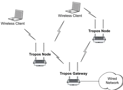
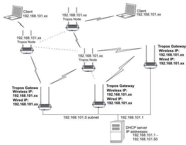
A Tropos wireless network consists of Tropos gateways connecting directly to the wired network and Tropos nodes delivering wireless communications support for clients and providing wireless backhaul to other upstream Tropos nodes and gateways. The Tropos routers form a
meshed cluster to dynamically route wireless signals from clients through the gateway and on to the wired network. Figure 1 illustrates a basic Tropos wireless network.
Chapter 1 Overview
Tropos Networks User Guide 3
Figure 1 Basic Tropos Wireless Network
Each Tropos node communicates with standard 802.11 clients and passes data back through a wireless link to a Tropos gateway attached to the wired network. All routers continually monitor the quality of the wireless links and jointly select the optimal path for routing traffic to the wired gateway. By overcoming the effects of interference and multi-path fading across the mesh, the Tropos network is able to deliver consistent throughput up to the maximum available with 802.11b/g.
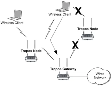
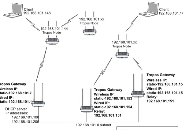
Routing decisions are made by way of the Tropos Predictive Wireless Routing Protocol (PWRP), which manages network routing based on self-organizing principles. The PWRP implements dynamic re-clustering to maximize available throughput and ensure reliability. Dynamic re-clustering refers to the ability of the network to respond to changes in radio signal availability and quality by modifying the paths that data packets take. As shown in Figure 2, when a node becomes unavailable or the signal quality degrades due to distance or other ambient
Wired Network Wireless Client Tropos Gateway Tropos Node Tropos Node Wireless Client
Chapter 1 Overview conditions, the network automatically reorganizes to create another path from the client through the mesh of Tropos nodes back the Tropos gateway and the wired network.
Figure 2 Typical Tropos Wireless Network
Due to dynamic re-clustering, it is not necessary to engineer individual paths on a link-by-link basis. The PWRP automatically sets up and maintains routes by dynamically identifying the path that achieves the highest throughput between the wireless client and the wired backhaul
connection. Changing interference conditions and new backhaul options are among the conditions that cause automatic regeneration of optimal paths. Overall network performance improves due to the maximization of throughput; and reliability increases because there is no system-wide single point of failure.
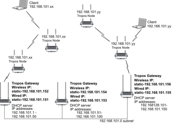
Tropos wireless networks permit easy addition of new Tropos routers to support growth in the number of client subscribers. You can add new nodes to extend coverage at any location with power. As the number of subscribers continue to grow, you can add new gateways to further increase coverage, performance, and reliability.
Tropos Mobile MetroMesh Networks
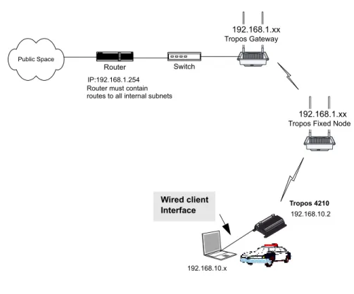
Tropos 4210 mobile MetroMesh routers extend the Tropos wireless network to mobile node operation. By installing Tropos 4210 routers in fire, police, or other public service vehicles, you can provide immediate high-bandwidth access to network services. As with other Tropos routers, the Tropos 4210 router dynamically associates to upstream nodes or gateways.
Wired Network Wireless Client
X
X
Tropos Gateway Tropos Node Tropos Node Wireless ClientChapter 1 Overview
Tropos Networks User Guide 5
Note
You can install Tropos 4210 routers in networks with mixed Tropos gateways and nodes (models 5210, 5110, 3210, and 3110). To support the Tropos 4210 routers, it is necessary for all routers to be running Tropos Release 5.0 or later software.
Clients connect to the Tropos 4210 router through a wireless or wired connection. In the typical vehicle installation, the client computer is connected directly to the Tropos 4210 router through a wired downstream sub-interface connection.
Since the Tropos 4210 routers may be in motion, special rules apply to the association of wireless clients to Tropos 4210 routers and from Tropos 4210 routers to other upstream nodes or gateways. The following guidelines and properties apply:
It is recommended that you configure a separate ESSID for the mobile nodes. Wireless clients accessing this ESSID will always try to associate to mobile nodes, and clients accessing other ESSIDs will always attempt to associate to fixed nodes. This arrangement prevents typical fixed clients from associating to mobile nodes that may move in and out of coverage, while also permitting special sets of wireless clients (such as passengers on a bus with a mobile node installed) to associate to the mobile nodes.
The Tropos 4210 router always attempts to establish backhaul connection to an upstream fixed Tropos node or gateway. If that is not possible, a router will attempt to connect to another 4210 router.
A fixed Tropos node will not attempt to establish uplink to a Tropos 4210 router.
If any Tropos router loses backhaul connectivity, it shifts to standalone mode so that it does not advertise wireless service to associated clients. When connectivity is recovered, service is automatically restored. This process takes approximately ten seconds after connectivity is re-established.
Because a mobile node is more likely to lose wireless connectivity than a fixed node, clients associated to a mobile node may encounter more frequent service disruptions than those associated to fixed nodes. To prevent unsuccessful data transmission attempts from the client when upstream connectivity is lost, the downstream wired interface for the Tropos 4210 is immediately switched off.
Chapter 1 Overview
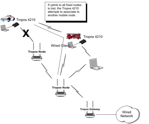
Figure 3 shows a typical Tropos network with mobile nodes added, and Figure 4 illustrates automatic rerouting actions if connectivity to the fixed Tropos network is interrupted.
Figure 3 Typical Tropos Mobile MetroMesh Network
Wired Network Tropos Gateway Tropos Node Tropos 4210 Tropos 4210 Wired Client Tropos Node
Chapter 1 Overview
Tropos Networks User Guide 7
Figure 4 Rerouting in a Tropos Mobile MetroMesh Network
Tropos Network Management and Administration
The Tropos Configuration Utility includes a secure HTTPS interface to control and manage each Tropos router. Connection is through the wired Management port on the Tropos router or association of a laptop client. This guide describes the configuration selections available through the Tropos Configuration Utility.Tropos Networks also offers the Tropos Control Element Management System (EMS) to administer multiple Tropos routers across the network. Tropos Control EMS includes network-wide fault monitoring to assess the overall state of the network and enables provisioning of multiple routers.
Together, the Tropos Configuration Utility and Tropos Control EMS provide a comprehensive administrative structure for managing the network.
X
Wired Network Tropos Gateway Tropos Node Tropos 4210 Tropos 4210 Wired Client Tropos NodeIf uplink to all fixed nodes is lost, the Tropos 4210 attempts to associate to another mobile node.
2
Getting Started
This chapter provides instructions on setting up Tropos MetroMesh routers to create a wireless network. Before you begin, make sure that you have followed the mounting and connection instructions detailed in the appropriate Tropos MetroMesh Router Installation Guide. See “Supporting Documentation” on page vii for a list of installation documentation.
This chapter contains information on the following topics: Setting Up a New Wireless Network
Setting the Gateway Configuration Using the Configuration Utility Adding Fixed Nodes to the Network Adding Clients to the Network Reassigning Gateways and Nodes Checking the Current Configuration Setting the Time
Setting Up a New Wireless Network
To form a Tropos wireless network, you first install and connect a Tropos router as a gateway and then expand network coverage by adding additional Tropos routers as nodes, ensuring that they are within radio range of each other.
The default settings in each Tropos router are intended for easy initial set-up. Each fixed router (Tropos 3110, 3210, 5110, or 5210) is shipped from the factory is pre-configured as a gateway. In this default configuration, the router configuration mode is “DHCP,” and the router receives an IP address from an external DHCP server. You can readily connect the new wireless network to an existing Ethernet network with working DHCP address services.
Each Tropos 4210 mobile MetroMesh router is shipped from the factory with the Mobile Node setting.
Chapter 2 Getting Started
Tropos Networks User Guide 9
Set up a new network
1. Follow the instructions in the appropriate Tropos MetroMesh Router Installation Guide (see list in “Supporting Documentation” on page vii) to unpack and connect power for the Tropos router you intend to use as your network gateway (Tropos gateway).
2. Connect an Ethernet cable from your working network to the LAN port on the Tropos gateway.
Note
The RJ45 connectors of the Tropos 5210 Outdoor router may source DC power on pins 4,5 and 7,8. The IEEE 802.3 standards allow for pins 4,5 and 7,8 to be used for Power Over Ethernet. Some products may be incompatible with the Tropos Power Over Ethernet capability. If such problems occur, make sure that the unit is configured with the Power Over Ethernet capability set to Off (default setting). If problems persist, use Ethernet cables that have no connections to the unused pins 4,5 and 7,8.
3. Power-up the Tropos gateway.
4. Wait for the status indicator light on the Tropos node to turn green (Tropos 5210, 4210, or 3210 router) or start blinking (Tropos 3210 or 3110 router). For more information on the operational lights, see “Viewing Equipment Status” on page 109.
A new wireless network is now established. Before adding nodes and clients to the network, it is strongly recommended that you access the Tropos Configuration Utility to confirm or modify configuration settings.
Note
If the status indicator light is red, check the cable connections. Make sure that DHCP services are working for other clients on the wired network. For further information on the power-up sequences for the Tropos routers, see “Viewing Equipment Status” on page 109.
Setting the Gateway Configuration
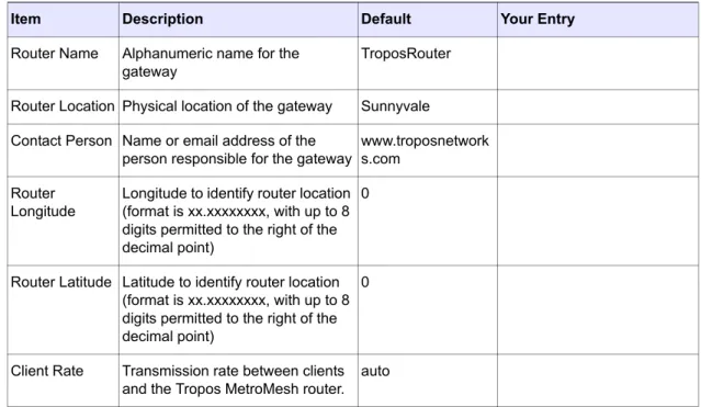
Use Table 1 to record basic configuration parameters for the Tropos gateway. Additional information regarding these parameters is contained in Chapter 3, “Configuring Wireless Settings.”
Note
The items identified in bold in Table 1must be the same for all gateways, nodes, and clients on the network.
Chapter 2 Getting Started
Table 1 Gateway Configuration Worksheet
Item Description Default Your Entry ESSID Unique, easy-to-remember
alphanumeric name for the network, with no spaces
TroposNetworks
ESSID Suppression
Indication of whether the Tropos router excludes the ESSID from the radio beacons it broadcasts. Can be assigned on a per-ESSID basis in multiple ESSID configurations
Disabled
Authentication Type
Client authentication method for the network
Open
WEP Type Encryption type, if WEP is selected as an authentication type
Hex64-bit
WEP Key Choice of encoding key, if WEP is enabled
aabbccddee
PSK Passphrase
Password used, if WPA-PSK is selected as an authentication type
whatever
RADIUS Server
IP address of a RADIUS
authentication server, if WPA-1x is selected as an authentication type
10.88.22.50
RADIUS Authentication Port
RADIUS server port used for authentication messages, if WPA-1x is selected as an authentication type
1812
RADIUS Secret
Password used for routers to connect to the RADIUS server, if WPA-1x is selected as an authentication type mysecret Wireless Routing Domain ID
Sixteen character string that uniquely identifies your network
1234123412341234
Router-Router Tx Rate
Desired rate for communications between Tropos routers in the network
11 Mbps
Channel Radio channel on which the gateway will communicate with downstream nodes and clients
Chapter 2 Getting Started
Tropos Networks User Guide 11
To configure the gateway settings, you must first configure your computer to start the Tropos Configuration Utility. Access to this utility is through the management port on the Tropos gateway.
Configure your computer to access the Tropos Configuration Utility
1. From the Start button, open the Network Connections control panel. Start→Settings→Network and Dial-Up Connections
or
Start→Control Panel→Network Connections
2. Right-click the Ethernet (for example, 10BaseT) or Local Area Connections icon for your PC, and select Properties.
3. Select Internet Protocol (TCP/IP), and click Properties. 4. Click Use the following IP address.
5. In the IP address box, enter the following IP address: 192.168.167.160. For wireless connection, use the address 192.168.166.160. These are the addresses that are pre-Router Name Alphanumeric name for the
gateway
Note
The router name is not displayed in the wireless client utility on the client’s PC. The router is identified only by MAC address.
TroposRouter
Router Location Physical location of the gateway Sunnyvale Contact Person Name or email address of the
person responsible for the gateway
www.troposnetworks. com
Router Longitude
Longitude to identify router location (format is xx.xxxxxxxx, with up to 8 digits permitted to the right of the decimal point)
0
Router Latitude Latitude to identify router location (format is xx.xxxxxxxx, with up to 8 digits permitted to the right of the decimal point)
0
Client Rate Transmission rate between clients and the Tropos router.
auto
Table 1 Gateway Configuration Worksheet (continued)
Chapter 2 Getting Started configured on each Tropos router. “Accessing the Configuration Utility Through a Wireless Connection” on page 27.
6. In the Subnet mask box, enter 255.255.255.0. 7. Click OK.
8. Click Close or OK to close the Local Area Connection Properties window. 9. If prompted, restart your computer.
You can now prepare to access the Tropos Configuration Utility. Access the Tropos Configuration Utility
1. Connect your computer to the port marked MGT on the Tropos router using an IEEE 802.3 RJ-45 DC blocking crossover cable.
2. Open the Web browser (Explorer or Netscape) on your PC.
3. In the URL window of the browser, enter the management IP address of the Tropos router: https://192.168.167.166. This is the address that is pre-configured on each Tropos router.
Note that you must use the secure https protocol, and not http.
4. If you receive security alerts about viewing pages over a secure connection, click Yes to proceed.
You may receive an additional security alert. The name of the security certificate issued by Tropos Networks may not match the name of the site.
Note
To avoid future security warnings, generate a security certificate according to the instructions in
“Generating SSL Certificates” on page 124. 5. Click Yes to proceed.
6. When the Enter Network Password dialog box opens, enter the username admin and password tropos.
7. Click OK.
The Tropos Configuration Utility opens.
To complete the initial gateway configuration, you must open the Wireless Configuration screen and verify the wireless settings for your network. Refer to Chapter 3, “Configuring Wireless Settings,” for instructions, using the values that you recorded in Table 1 on page 10.
Chapter 2 Getting Started
Tropos Networks User Guide 13
Using the Configuration Utility
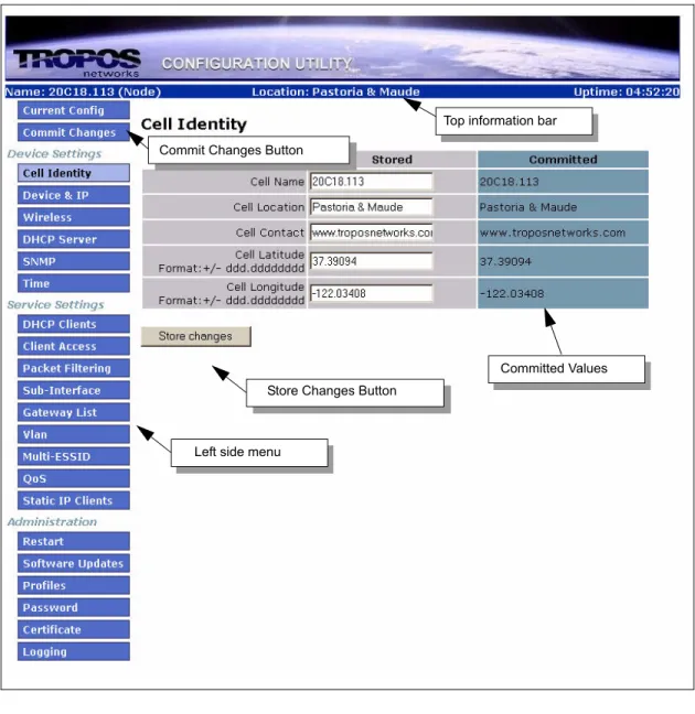
The left side menu of the Configuration Utility, shown in Figure 5, provides access to all the configuration screens. This guide explains how to use each screen; for a complete list of parameters on each screen, refer the Tropos Networks Configuration Reference Guide.
Figure 5 Configuration Utility Interface
Top information bar
Left side menu Commit Changes Button
Store Changes Button
Chapter 2 Getting Started
Top Information Bar
The top information bar displays the following information: Name assigned to the router
Global Positioning System (GPS) coordinates, if they are available from an external GPS receiver installed with the router. Only Tropos qualified GPS receivers are supported. For further information, see the Tropos 4210 Mobile MetroMesh Router Installation Guide. Length of time since the router was last powered up.
Committing Changes
For flexible control over configuration changes, the Configuration Utility provides the ability to build configuration changes and then choose when to make them operational. To make a configuration change, you first store the changes in a temporary location. You can then choose when to commit the changes and whether there should be a time delay. During the window of time between committing changes and having the changes take place, you can cancel the process.
After you commit changes, the committed values are displayed in a read-only column at on the right side of the screen, as shown in Figure 5.
Store configuration changes
Click Store Changes at the bottom of the configuration screen.
Commit configuration changes that you have previously stored
1. Click Commit Changes on the left menu bar to open the Commit Changes screen. 2. Enter a time delay in seconds, if desired.
3. Click the Commit Changes button.
To confirm the new settings, return to the screen or screens on which you made the changes and view the values in the Committed column.
Cancel changes that have been requested
1. Open the Commit Changes screen. 2. Click Cancel Changes.
Note
Chapter 2 Getting Started
Tropos Networks User Guide 15
Adding Fixed Nodes to the Network
With the Tropos gateway set up and configured, you can now add fixed Tropos nodes to the network. First use the configuration worksheet in Table 2 to enter wireless configuration settings for the nodes. The items in bold must be the same for all gateways, nodes, and clients on the network.
Add nodes to the network
1. Supply power to the Tropos router you plan to use as a node (Tropos node). Do not connect an Ethernet cable to the LAN port. Instead, connect your computer to the port labeled MGT on the Tropos router using an IEEE 802.3 RJ-45 DC blocking crossover cable.
2. Open the Configuration Utility according to the instructions in “Access the Tropos Configuration Utility” on page 12.
3. Select Device & IP.
4. On the Device & IP Configuration screen, change the router setting to Node.1 5. Click Store Changes.
6. Select Wireless on the side menu.
7. On the Wireless Configuration screen, enter or confirm the values in Table 2. 8. Click Store Settings.
9. To commit the changes made on the Device & IP Configuration screen and the Wireless Configuration screen, select Commit Changes from the side menu. Enter a time delay, if desired, and click Commit Changes.
Monitor the status indicator on the Tropos node. When the status indicator light turns green (Tropos 5210/4210/3210 routers) or starts blinking (Tropos 5110/3210 router), the node is fully connected and communicating with the Tropos gateway. You can now add additional nodes or client stations. For more information on the operational lights, see “Viewing Equipment Status” on page 109.
Note
If the status indicator light is red, check the cable connections. Make sure that DHCP services are working for other clients on the wired network. For further information on the power-up sequences for the Tropos routers, see “Viewing Equipment Status” on page 109.
Chapter 2 Getting Started
Table 2 Node Configuration Worksheet
Item Description Default Your Entry ESSID Unique, easy-to-remember
alphanumeric name for the network, with no spaces
TroposNetworks
ESSID Suppression
Indication of whether the Tropos router excludes the ESSID from the radio beacons it broadcasts. Can be assigned on a per-ESSID basis in multiple ESSID configurations
Disabled
Authentication Type
Client authentication method for the network
Open
WEP Type Encryption type, if WEP is selected as an authentication type
Hex64-bit
WEP Key Choice of encoding key, if WEP is enabled
aabbccddee
PSK Passphrase
Password used, if WPA-PSK is selected as an authentication type
whatever
RADIUS Server
IP address of a RADIUS
authentication server, if WPA-1x is selected as an authentication type
10.88.22.50
RADIUS Authentication Port
RADIUS server port used for authentication messages, if WPA-1x is selected as an authentication type
1812
RADIUS Secret
Password used for routers to connect to the RADIUS server, if WPA-1x is selected as an authentication type mysecret Wireless Routing Domain ID
Sixteen character string that uniquely identifies your network
1234123412341234
Router-Router Tx Rate
Desired rate for communications between Tropos routers in the network
11 Mbps
Channel Radio channel on which the gateway will communicate
6 Router Name Alphanumeric name for the
gateway
TroposRouter Router Location Physical location of the gateway Sunnyvale
Chapter 2 Getting Started
Tropos Networks User Guide 17
Adding Mobile Nodes to the Network
To add Tropos 4210 mobile MetroMesh routers to the network, first use the configuration worksheet in Table 3 to enter wireless configuration settings for the nodes. The items in bold must be the same for all gateways, nodes, and clients on the network.
Add nodes to the network
1. Install the Tropos 4210 node according to the instructions in the Tropos 4210 Mobile MetroMesh Router Installation Guide. Connect your computer to the port labeled MGT on the Tropos router using an IEEE 802.3 RJ-45 DC blocking crossover cable.
2. Open the Configuration Utility according to the instructions in “Access the Tropos Configuration Utility” on page 12.
3. Select Device & IP.
4. On the Device & IP Configuration screen, confirm that the settings is Mobile Node. 5. Click Store Changes.
6. Select Wireless on the side menu.
7. On the Wireless Configuration screen, enter or confirm the values in Table 3. 8. To use the automatic channel selection option for the node, follow these steps:
a. Choose auto from the Channel pull-down list, and click Store Changes. The screen reopens to display an entry area for the channels you would like make available for automatic selection.
Contact Person Name or email address of the person responsible for the gateway
www.troposnetwork s.com
Router Longitude
Longitude to identify router location (format is xx.xxxxxxxx, with up to 8 digits permitted to the right of the decimal point)
0
Router Latitude Latitude to identify router location (format is xx.xxxxxxxx, with up to 8 digits permitted to the right of the decimal point)
0
Client Rate Transmission rate between clients and the Tropos router.
auto
Table 2 Node Configuration Worksheet (continued)
Chapter 2 Getting Started b. Enter up to six channels. The default channels are 1, 6, and 11.
9. Click Store Changes.
10.To commit the changes made on the Device & IP Configuration screen and the Wireless Configuration screen, select Commit Changes from the side menu. Enter a time delay, if desired, and click Commit Changes.
Monitor the status indicator on the Tropos node to determine when it is fully connected and communicating with the Tropos gateway. For more information on the operational lights, see “Viewing Equipment Status” on page 109.
When the node is fully connected and communicating with the gateway or other nodes, you can add additional nodes or client stations. If the router does not start communicating with the gateway or other nodes, check to see whether the settings for ESSID, WEP, and Wireless Routing Domain ID exactly match those in the router.
Chapter 2 Getting Started
Tropos Networks User Guide 19
Table 3 Tropos 4210 Configuration Worksheet
Item Description Default Your Entry ESSID Unique, easy-to-remember
alphanumeric name for the network, with no spaces
TroposNetworks
ESSID Suppression
Indication of whether the Tropos MetroMesh router excludes the ESSID from the radio beacons it broadcasts. Can be assigned on a per-ESSID basis in multiple ESSID configurations
Disabled
Authentication Type
Client authentication method for the network
Open
WEP Type Encryption type, if WEP is selected as an authentication type
Hex64-bit
WEP Key Choice of encoding key, if WEP is enabled
aabbccddee
PSK Passphrase
Password used, if WPA-PSK is selected as an authentication type
whatever
RADIUS Server
IP address of a RADIUS
authentication server, if WPA-1x is selected as an authentication type
10.88.22.50
RADIUS Authentication Port
RADIUS server port used for authentication messages, if WPA-1x is selected as an authentication type
1812
RADIUS Secret
Password used for routers to connect to the RADIUS server, if WPA-1x is selected as an authentication type mysecret Wireless Routing Domain ID
Sixteen character string that uniquely identifies your network
1234123412341234
Router-Router Tx Rate
Desired rate for communications between Tropos routers in the network
11 Mbps
Channel Radio channel on which the gateway will communicate. To activate the auto-select channel option for mobile nodes, choose
auto.
Chapter 2 Getting Started
Adding Clients to the Network
The process of configuring client PC settings to use the Tropos wireless network varies somewhat according to the operating system of the PC. This section provides the standard Windows instructions for Windows XP and Windows NT or 2000.
Note
If you are configuring the network for WPA security, you can configure this option in Windows XP by using the Wireless Zero Config (WZC) feature, as explained in this section. To configure WPA security on Windows 2000, it is necessary to use a third party tool such as Funk Odyssey for configuration. You can also use Funk Odyssey with Windows XP.
Setting the Client Configuration
The instructions in this section apply if you are using the Windows configuration utility, not one that was supplied with the wireless network card.
Note
Make sure the client network adapter (wireless adapter) is set for DHCP so that an IP address is automatically assigned to the client device.
Router Name Alphanumeric name for the gateway
TroposRouter Router Location Physical location of the gateway Sunnyvale Contact Person Name or email address of the
person responsible for the gateway
www.troposnetwork s.com
Router Longitude
Longitude to identify router location (format is xx.xxxxxxxx, with up to 8 digits permitted to the right of the decimal point)
0
Router Latitude Latitude to identify router location (format is xx.xxxxxxxx, with up to 8 digits permitted to the right of the decimal point)
0
Client Rate Transmission rate between clients and the Tropos MetroMesh router.
auto
Table 3 Tropos 4210 Configuration Worksheet (continued)
Chapter 2 Getting Started
Tropos Networks User Guide 21
Configure a Windows XP PC client
1. From the Start button, select Control Panel→Network Connections. 2. Right-click the Wireless Connections icon and select Properties. 3. Click the Wireless Networks tab.
4. Select the desired network from the list. If the desired network is not available and you would like to add it, click Add, and enter requested information (including the ESSID in the SSID field).
5. Click Properties.
6. The next steps depend upon the selections that you make on this screen. For further information on security options, see Chapter 3, “Configuring Wireless Settings.” WEP Security:
a. Select Open under Network Authentication, and select WEP for data encryption. b. Enter and confirm the WEP key or select the WEP Enabled checkbox, or indicate if the
key is provided automatically in your network. c. Click OK as needed to close the Properties windows. WPA-PSK Security:
a. Select WPA-PSK under Network Authentication. b. Select AES or TKIP for data encryption.
Chapter 2 Getting Started d. Click OK as needed to close the Properties windows.
WPA-1x Security:
a. Select WPA under Network Authentication. b. Select AES or TKIP for data encryption. c. Select the Authentication tab.
.
d. Confirm that the EAP type is “Smart Card or other Certificate.”
e. Confirm that the checkbox entitled “Authenticate as computer when computer information is available” is selected.
Chapter 2 Getting Started
Tropos Networks User Guide 23
f. Click Properties to open the Certificate Properties box.
g. Confirm that “Use a certificate on this computer” is selected along with “Use simple certificate selection.”
h. Select the checkbox entitled “Validate server certificate.”
i. Select the checkbox “Connect to these servers” and enter the IP address of your RADIUS authentication server.
j. Select the certificate authority or authorities approved for your network. The list should include the certificate authority used for your RADIUS server.
k. Select the checkbox entitled “User a different user name for the connection.” l. Click OK as needed to close the Properties windows
Configure a Windows NT or 2000 PC client
1. From the Start button select Settings→Network and Dial-Up Connections. 2. Right-click the Local Area Connections icon and select Properties.
3. Select Client for Microsoft Networks and click Configure. 4. Click the Advanced tab.
5. Select SSID from the list on the left, and enter the ESSID for your network in the space provided.
Chapter 2 Getting Started 7. Click the Wireless LAN Configuration Utility icon in the system tray at the bottom of your
screen.
8. Click the Configuration tab.
9. Select Infrastructure from the Mode list. 10.Select the SSID pull-down menu.
11.Click the Encryption tab.
12.Select the WEP option that matches your network (enabled or disabled). If you select one of the WEP options, enter the key for your network.
13.Click OK.
Once you have configured the settings on a client device, the device requests an IP address from the wireless network. The client then receives IP address, default route assignment and DNS settings from a DHCP server which may be on the wired network or on an Tropos gateway within your wireless network.
Reassigning Gateways and Nodes
Gateway is the factory default setting for the Tropos router; however, you can change a gateway to a node or a node to a gateway.
Change the gateway or node setting
1. Open the Configuration Utility. 2. Click Device & IP on the side menu.
3. Select Gateway or Node from the Router Setting pull-down menu.
4. Click Store Changes, and then select Commit Changes on the side menu to implement the change. Enter a time delay, if desired, and click Commit Changes. After you commit the changes, they are displayed in the Committed columns on the screens.
The new setting is indicated at the top of the Configuration Utility screen (see Figure 5 on page 13).
Note
The Tropos gateway reverts to node operation automatically if it loses connection to the Ethernet network. The label at the top of the Configuration Utility screen does not change, however, and the router reverts back to gateway operation as soon as network connectivity is re-established.
Chapter 2 Getting Started
Tropos Networks User Guide 25
Confirming Router Identity
Use the Router Identity screen, shown in Figure 6, to record information about the name and location of the Tropos router.
Figure 6 Router Identity Screen
Set the router identity
1. Open the Configuration Utility. 2. Select Identity from the side menu.
3. Enter an alphanumeric name and location for the router.
4. Enter the name or email address of the contact person for issues relating to router operation. 5. Enter the longitude and latitude that represent the global position of the Tropos router. The
fields are in the format xx.xxxxxxxx, with up to 8 digits permitted to the right of the decimal point.
6. Click Store Changes.
Chapter 2 Getting Started
Checking the Current Configuration
Check current configuration settings at any time by selecting Current Config from the side menu of the Configuration Utility (Figure 7). For detailed information about the information on this screen, refer to the Tropos Networks Configuration Reference Guide.
Chapter 2 Getting Started
Tropos Networks User Guide 27
Accessing the Configuration Utility Through a Wireless
Connection
It is not always convenient or possible to access the Tropos Configuration Utility using a direct cable connection to the Management port. To address this concern, Tropos routers support the ability to connect to the Configuration Utility using a wireless connection.
Access the Configuration Utility through a wireless connection
1. Configure a laptop computer to access the Tropos Configuration Utility according to the instructions in “Setting the Gateway Configuration” on page 9.
2. Associate the laptop to the Tropos router. To do so, turn off other routers within range or move the laptop close enough to associate to the router.
3. Open a Web browser.
4. In the URL window of the browser, enter the wireless management IP address of the Tropos router: https://192.168.166.166. This is the wireless address that is pre-configured on each Tropos router. Note that you must use https, not http.
5. You may receive a security alert about viewing pages over a secure connection. Click Yes to proceed.
6. You may receive an additional security alert. Note that the name of the security certificate, which is issued by Tropos Networks, may not match the name of the site. Click Yes to proceed.
Note
To avoid future security warnings, generate a security certificate according to the instructions in
“Generating SSL Certificates” on page 124.
7. When the Enter Network Password dialog box appears, enter the username admin and password tropos.
Chapter 2 Getting Started
Setting the Time
The Tropos router supports accurate time setting through connection to a Network Time
Protocol (NTP) server. Use the Time screen (Figure 8) to configure connection to an NTP server, identify the time zone in which the router is operating, or set the time manually. If you use NTP, it is not necessary to set the time manually.
Figure 8 Time Screen
Set the time
1. Select Time from the side menu.
2. To use an NTP server for time synchronization:
Select the time zone from the Timezone pull-down list. The UTC option refers to Universal Time Coordinated, which is the same as Greenwich Mean Time.
Enter the IP address of an NTP server or servers in the Time Servers field. You must specify a server if NTP is used. You can enter multiple servers using comma-separated IP addresses.
Click Store Changes. When you have finished, click Commit Changes on the side menu.
3. To set the time manually, select from the pull-down lists at the bottom of the screen, and click Set Time.
Note
It is not necessary to commit your changes when setting the time manually; the time is applied immediately without commit. It is necessary to commit the changes when configuring time using an NTP server.
Chapter 2 Getting Started
Tropos Networks User Guide 29
Note
Enabling NTP on a router after a DHCP lease has already been obtained may change the duration of the DHCP lease.
3
Configuring Wireless Settings
This chapter describes how to set the parameters that control radio frequency (RF)
communications in the Tropos wireless network. It contains information on the following topics: Service Sets
Transmission Rates and Channels Security
Roaming
Multiple ESSIDs
Power Levels and Transmit Antenna Diversity Setting the Wireless Configuration
Configuring Multiple ESSIDs
Service Sets
Each Tropos MetroMesh router, together with associated clients, forms a Basic Service Set (BSS), or 802.11 wireless communications unit. Multiple routers, such as those in a Tropos cluster, form an Extended Service Set (ESS), also known as an 802.11 wireless network. The alphanumeric Extended Service Set Identifier (ESSID) functions as a group identifier. By entering the same ESSID into every Tropos gateway, node, and client, you add all of the wireless devices into the same wireless network.
Each Tropos gateway is shipped with a default ESSID, which you should change to uniquely identify your own wireless network. Select an alphanumeric string (no spaces) that is unique to your organization and easy to remember.
By default, the ESSID is sent in the RF beacon of each wireless device in the network. It is possible to suppress the ESSID broadcast for the Tropos router, thereby excluding the ESSID from the packets the router transmits and making it more difficult for unauthorized devices to obtain the ESSID and detect the presence of the wireless network. In multiple ESSID
Chapter 3 Configuring Wireless Settings
Tropos Networks User Guide 31
Transmission Rates and Channels
Tropos routers conform to the IEEE 802.11b and 802.11g specifications for wireless
communications, which apply to the 2.4 GHz RF band. The data transmission rates that apply between client machines and the Tropos router and between Tropos routers are
user-configurable. The supported data rates range up to 54Mbps.
The Router-Router Tx Rate parameter determines the data rate for communications between Tropos routers. The default setting is 5.5 Mbps. If path quality is excellent, it may be possible to increase the data rate to 11Mbps (for the Tropos 3110 and 5110 routers) or 54Mbps for the (Tropos 5210, 4210, and 3210 routers) without suffering loss of path quality. If router-to-router connections are subject to interference or router density is low, it may be necessary to lower the data rate setting to 1 or 2Mbps.
The wireless channels that clients use when associating to Tropos router are user-configurable. The most commonly used channels for 802.11b/g communications are 1, 6, and 11 because they operate in non-overlapping frequency bands.
If you have multiple wireless networks in the same vicinity, determine what channels the other networks are using, and configure your Tropos routers on a different channel. Make sure all of the wireless router on the same network are set to the same channel.
Automatic Channel Selection
Automatic channel selection is supported. If you choose auto, you can enter a set of channels from which the router chooses an operating channel. The following automatic channel rules apply for gateways, fixed nodes, and mobile nodes:
Gateway: When the gateway is booted, it cycles through the channel list to find the best channel for operation based upon noise measurements and radio signal interference. That channel is used for communications within the cluster. During operation, the gateway measures channel noise in 10 minute windows. The gateway continues to use the selected channel until one of the following occurs:
The measurements indicate that noise exceeds a pre-set threshold. The gateway performs a channel cycle, measuring the noise on all the channels in the channel list in a 10 minute window. If a channel with lower average noise during that period is identified, then the gateway shifts to that channel.
During the configured maintenance window, the gateway identifies a channel with better noise characteristics than the current channel. If so, the gateway shifts the cluster to that channel. The maintenance window last 1.5 hours, beginning at the configured time and day (default interval is 1 day).
Fixed node: Fixed nodes collect signal data every 10 minutes. The node changes channels if any of the following occur:
Chapter 3 Configuring Wireless Settings
If the packet success probability (PSP) drops below a pre-set threshold, then the node performs a channel cycle to determine if another channel with better PSP characteristics is available. If a better channel is found, the node switches. This includes the case in which the current channel is no longer available because the gateway has switched to a different channel.
If the gateway has selected a new operating channel during a maintenance window, then all nodes in the cluster are reconfigured to use that channel.
Mobile node: Upon boot-up, Tropos 4210 mobile nodes scan for the best available channel. During normal operations, a mobile node will scan for another channel if the following applies: If the packet success probability (PSP) drops below a pre-set threshold, then the node
performs a channel cycle to determine if another channel with better PSP characteristics is available. If a better channel is found, the mobile node switches.
Security
Tropos provides several options for securing client access and traffic in the wireless network and for securing control and management traffic between Tropos routers.
Client Security
The client authentication options available today reflect evolving technology and the need for continuing responses to attempts to compromise existing security solutions. The current generation solutions are part of the Wi-Fi Protected Access (WPA) standard, some of which is codified in the IEEE 802.1x standard for user authentication with a central authentication server. Adopted by the Wi-Fi Alliance in response to needs for improved security, the WPA solutions encompass the central authentication methods now included in 802.1x plus a method for decentralized authentication using pre-shared keys.
Previous generation security is based on the Wired Equivalence Privacy (WEP) standard. Although not as effective as the WPA solutions, WEP is still widely used.
802.1x
The 802.1x approach relies on an external authentication server that verifies client identity by means of digital certificates. The most widely used authentication servers are based on the Remote Authentication Dial-In User Service (RADIUS) protocol, which allows the Tropos gateway to communicate with the authentication server to exchange certificate information. Authentication messages sent between the RADIUS server and Tropos routers are protected by means of Extensible Authentication Protocol with Transport Layer Security (EAP-TLS) and EAP with Tunneled Transport Layer Security (EAP-TTLS).
Chapter 3 Configuring Wireless Settings
Tropos Networks User Guide 33
If a RADIUS authentication server is accessible to the Tropos network, you can implement 802.1x authentication and RADIUS accounting by configuring the following parameters:
RADIUS accounting enables you to do the following:
Limit the number of concurrent sessions for a user account.
Examine client roaming patterns to better respond to client support requests.
Track unauthorized usage by linking a MAC address to a client at a specific time with evidence of traffic usage.
Enable for-fee client service based upon usage plans.
Correlate client activities with network events to detect whether a client has poor compatibility or is sending destabilizing traffic.
Detect client-to-client traffic that might indicate hacking attempts.
Determine the nodes that experience the most traffic flow or the times of day that are the busiest.
WPA with Pre-Shared Keys
Organizations that do not have a centralized authentication server can still take advantage of strong WPA authentication security by using the WPA pre-shared key (PSK) option. In the WPA-PSK approach, each network device for which authentication is required is configured with the same password, or key. Clients access the network by presenting the password. As with RADIUS authentication, WPA-PSK uses EAP to send authentication messages.
WPA/802.1x and WPA-PSK are compatible with a variety of data encryption options. Tropos currently supports the Advanced Encryption Standard (AES) and Temporal Key Integrity Protocol (TKIP). The encryption method is determined by settings on the client station.
RADIUS Authentication
Server
IP address of the RADIUS server
RADIUS Authentication
Port
Server port number for authentication requests
RADIUS Authentication
Secret
Pass code for authorization of authentication requested by
the Tropos router
RADIUS Accounting
Server
IP address of the RADIUS accounting server used to log
client activity
RADIUS Accounting
Port
Server port number for RADIUS accounting requests
RADIUS Accounting
Secret
Passcode to verify the connection between the accounting
server and the Tropos router
RADIUS Accounting
Interval
Chapter 3 Configuring Wireless Settings
Wired Equivalent Privacy
Wired Equivalent Privacy (WEP) is an earlier generation wireless authentication and encryption solution that is still widely used, especially in devices that are not equipped to support WPA/ 802.1x. WEP relies on security keys, which must be the same on all Tropos routers and all client devices. From a user perspective, the process of configuring WEP keys is similar to configuring WPA keys; however, the authentication algorithms are not as secure as the EAP algorithms. The Tropos router supports two types of WEP keys
64-bit Key. This key length consists of 40 bits of data encryption plus a 24-bit initialization number generated randomly by the WEP encryption algorithm. Total key length is 64-bit. 128-bit Key. This key length consists of 104 bits of data encryption plus a 24-bit
initialization number generated randomly by the WEP encryption algorithm. Total key length is 128-bit.
Example keys:
64-bit ASCII: AZY23
128-bit ASCII: 9843DTGKLH334 64-bit hexadecimal: 0A3C4D5F4B
128-bit hexadecimal: 987ADE78F4458DDB03489CA00F
After creating a key, you can use it to program all client devices and Tropos routers in the wireless network.
Client Security Options
In addition to the authentication options listed in this section, the Tropos router supports the option of forgoing authentication and encryption entirely and permitting clients to access the network with no protection for data traffic. This option provides no protection for clients and should not be selected if network security is of concern.
The Tropos 5210, 4210, and 3210 routers support Open, WEP, WPA-PSK, and WPA-1x security. For WPA-PSK and WPA-1x, the encryption method is determined by settings on the client machine. In networks with multiple ESSIDs, each ESSID can be configured to support a different authentication type.
The Tropos 3110 and 5110 routers support only WEP and Open security.
Router-to-Router Security
All control and management communication between Tropos routers is encrypted at Layer 3 using Advanced Encryption Standard (AES). In Tropos networks comprised of Tropos 3210 and 5210 routers, you can elect to add additional protection for router-to-router data and control traffic by enabling the AES Encrypt Forwarded Packets feature on the Wireless screen. The following guidelines apply to the AES Encrypt Forward Packet feature:
Chapter 3 Configuring Wireless Settings
Tropos Networks User Guide 35
The feature should be enabled in networks with 5210, 4210, and 3210 model routers that use WPA-1x or WPA-PSK security.
If AES Encrypt Forwarded Packets is enabled, then all gateways and nodes in the cluster must have at least one SSID configured for WPA-PSK or WPA-1x.
AES Encrypt Forwarded Packets should be disabled for Tropos 4210 mobile nodes and to assure communications in networks with a mix of 5210/4210/3210 and 5110/3110 router models. For the highest level of router-router security, assign the 5210/4210/3210 routers to a different wireless routing domain (WRD) than the 5110/3110 routers.
If AES Encrypt Forwarded Packets is disabled, router-to-router communications use the security settings for the primary ESSID (as set on the Wireless screen).
Beacon Rates
It is possible to change the rate at which 802.11 beacons are transmitted from the router and to change the interval between beacons. The default settings for beacon rate and beacon interval (11 Mbps and 250 ms) should work well in almost all situations; however, it may be desirable to change the rates to support some non-compliant client devices or network configurations. In large, highly connected networks in which each router has numerous neighbors, the overhead from 802.11 beacons could become significant. Increasing both the beacon interval and beacon rate may reduce the overhead without a significant impact on network performance.
Roaming
Since clients operate at lower power than nodes, nodes may be able to detect a client even if the client cannot detect the node. Network initiated roaming detects clients that lose uplink to a node, and forces them to associate to another neighboring node. This feature is disabled by default, and should be used with care. Client systems function in different ways, and tuning may be required for network initiated roaming to operate effectively with multiple client platforms. Client initiated roaming is automatically supported throughout the network wireless routing domain, which is identified by the Wireless Routing Domain ID.
Multiple ESSIDs
The Tropos 5210, 4210, and 3210 routers can support multiple ESSIDs. When multiple ESSIDs are configured, the router accepts packets destined for any of configured ESSIDs and forwards them to the appropriate networks. Multiple ESSIDs are used in conjunction with virtual LANs (VLANs) to support multiple use networks. For further information, see “Configuring VLANs” on page 89.
Configured on the Wireless screen, the primary ESSID is the identifier that is advertised in the router’s beacon (“Setting the Wireless Configuration” on page 37). In addition to the primary
Chapter 3 Configuring Wireless Settings ESSID, it is possible to define up to 15 additional secondary ESSIDs. the Tropos router will accept and forward packets intended for those networks.
Configuring a secondary ESSID creates a virtual interface for the wlan0 radio interface. The interface is designated as wlan0sN, where N is the number of secondary interfaces that have been created. For example, wlan0s1 refers to the first secondary ESSID.
You can configure the authentication type on a per ESSID basis. The authentication type for the primary ESSID is set on the Wireless screen (“Setting the Wireless Configuration” on page 37), and the authentication types for secondary ESSIDs are set on the Multi-ESSID screen. See “Configuring Multiple ESSIDs” on page 39 for configuration instructions.
If an ESSID has authentication type as Open, then you cannot create another ESSID using WEP. The combination is not supported. Multiple ESSIDs using the same authentication type will also use the same encryption configuration. In order to choose WPA authentication, you must first enable AES packet forwarding on the Wireless screen (“Setting the Wireless Configuration” on page 37).
You can enable or disable ESSID suppression on a per-ESSID basis. If ESSID suppression is disabled, then the ESSID is included in the router’s beacon. If you enable suppression, then the ESSID is not sent in the beacon.
Note
In order for clients to see all non-suppressed ESSIDs from the Windows Wireless Zero Config (WZC) window, it is necessary to refresh the display once for each ESSID. Each time the screen is refreshed, another ESSID is added to the list. In addition, make sure that none of the ESSIDs is configured as a preferred network in WZC.
Power Levels and Transmit Antenna Diversity
To adjust the power output of the Tropos router radio, set the attenuation level for transmit power. Increasing the attenuation reduces the output power of the router; reducing the attenuation increases the output power. Available settings range from 0dB to 10dB in 1bB increments. When 0dB is selected, the router operates at full power; when 20dB is selected, the router operates at the lowest positive power setting.You can also assign following antenna diversity settings:
Auto – automatically pick the Tx (transmit) antenna (automatic transmit diversity) Main – use the main antenna only for transmit
Chapter 3 Configuring Wireless Settings
Tropos Networks User Guide 37
Setting the Wireless Configuration
Use the Wireless Configuration screen (Figure 9) to change wireless parameters. For further information, refer to the Tropos Networks Configuration Reference Guide.
Figure 9 Wireless Configuration screen
Chapter 3 Configuring Wireless Settings
Change wireless configuration settings
1. Choose Wireless from the side menu to open the Wireless Configuration screen.
2. Enter or confirm the primary ESSID and indicate whether the ESSID will be suppressed in the router’s 802.11 beacon.
3. Select the transmission rates for client communications in the Client Transmit Rate field. The Automatic setting is acceptable for most networks.
4. Select the transmission rate for communications between Tropos routers in the Router-Router Tx Rate field.
5. Choose an operating channel, or choose auto and click Store Changes to use automatic channel selection.
If you choose auto and click Store Changes, the screen reopens to display the channel list fields. Enter up to six channels.
If the router is a gateway and you choose auto, the screen reopens to display the channel list fields and channel maintenance fields. Enter the hour, date, month, and year for the maintenance window, and also enter the interval at which the maintenance window repeats. For example, the de