Photo VR: A System of Rendering High Quality Images for Virtual
Environments Using Sphere-like Polyhedral Environment Maps
Wen-kae Tsao Jiunn-jia Su Bing-yu Chen Ming Ouhyoung
Communication and Multimedia Lab.
Department of Computer Science and Information Engineering National Taiwan University, Taipei, Taiwan, R.O.C.
Abstract
In the first part of this paper, we describe a novel method of panoramic view rendering for real-time interactive applications trying to present a real-world like environment. This is different from the QuickTime VR approach, and is accomplished by generating a sphere-like polyhedral environment map from photo-realistic images and using the generated maps to render the scene by techniques of computer graphics. In the second part, we purpose a simple image-based method for observing a certain object from different views interactively. We call it "object viewer." Although some precision in alignment is lost, the high complexity, high quality and high frame rate performance on a Pentium PC without any hardware supported makes this approach attractive in low cost systems.
Introduction
Traditionally, when we want to render a scene in the real world, we model the scene by geometric elements, such as triangles, and then render these objects. However, this method usually works well only when the quantity and complexity of objects are relatively low, often far below those in the real world. Furthermore, the shading is either too slow or unrealistic. On the other hand, the quantity and complexity of objects in images taken from a camera are almost the same as those in the real world.
In recent years, some method of image-based rendering has been developed, such as "image warping" used by "QuickTime VR" of Apple Computer [1][2], or texture mapping used by us [3]. These methods render the scene by using cylinderic or prismatic environment maps generated from images of the whole 360-degree view of the scene. However, these methods have a common problem: the environment map used can not cover the top view and the bottom view, so the vertical viewing angle is limited. In the following, we will propose a better method that renders the scene by sphere-like polyhedral environment maps, and thus the problem is solved.
If the above problem is solved, we still have another one, say object viewer, for real applications. The traditional method for observing an object from all views is to generate a polygon model of the object, and then the model is rendered from different view points. However, it is difficult or impossible to generate a model for some objects, such as a fuzzy teddy or a valuable artifact. We then propose an image-based method to solve this problem.
Texture Mapping Approach
To render the scene in a room, we propose a way to put a camera in a proper position, such as the center of the room, and then take images of the whole view from the camera position. These images are arranged as a sphere-like polyhedron consisting of textured trapezoids. This polyhedron forms the environment map of the scene and is used as the 3D model for rendering. It is clear to see that, when moving around the center of this sphere-like polyhedron, the image presented to the user will approximate the one rendered by traditional method used in computer graphics or even the one seen in the real world if all objects in the room are a certain distance away from the center.
To render such a sphere-like polyhedron is quite easy: no shading is required. No hidden surface problem occurs. (Polygonal) texture mapping is usually contained in rendering packages, libraries or graphic hardware accelerators. Thus high complexity, high quality and high frame rate become possible even on low cost PC systems.
To allow a user walk around the scene, one can generate several such sphere-like polyhedrons by taking images from several different positions, each corresponding to a "visible area" in the scene. One polyhedron is rendered at a time, and only when the user is in the corresponding "visible area" will the polyhedron be rendered. Adjacent visible areas will be overlapped instead of providing a clear border (figure 4), and if a user is in the overlapped area, only the previously rendered
polyhedron will be rendered to avoid frequent switching of 3D models when the user moves around the border. We will describe this more clearly with an example later in this paper.
The switching between 3D models will be observed by the user, just like the switching of acts in a film. Because the switching is performed when the viewpoint is moving, it will not be so annoying to the user. However, it is a problem remaining unsolved by us yet. Linear interpolation is, perhaps, not a practical solution. Not only because the time for rendering will be at least doubled (for at least 2 cylinder-like prisms need to be rendered), but also because the interpolation may involve theories in computer vision: objects in images must be identified and located for interpolation. The complexity of these interpolated images taken from the two real environment images usually makes this process (object identification) too slow and even impossible. However, if geometric information of the scene is available and objects in the images are identified in advance, interpolation (such as morphing) might be possible.
Generate the Sphere-like Polyhedron Assumptions
The following are four assumptions of our system:
1. Geometric distortion of the camera lens is negligible (ideal perspective projection).
2. The size, camera constants, horizontal and vertical view angles of different images are the same.
3. All objects in the scene are far enough from the camera such that the movement of the COP (center of projection) caused by panning the camera is negligible. Thus all optic axes of the images can be regarded as intersected at the COP.
4. Each image is perpendicularly intersected by its optic axis at its center.
Camera Calibration
First, we have to measure the horizontal and vertical viewing angle of the camera. Then we convert horizontal viewing angle to the camera constant Fw, and convert vertical viewing angle to the camera constant Fh:
Fw
W: image width
Fw = W 2
cot horizontal viewing angle 2
Fh
H: image height
Fh = H 2
cotvertical viewing angle 2
Image Registration
If we do not know the absolute orientation of the camera of each image, we can register the image by hand. In our implementation, we provide a tool for automatic registering by using the corresponding points within the related portion of the environment map. If the result is unacceptable, we provide another tool allowing a user to manually register images or modify the registration. The change can be processed in almost real-time.
Model Generation
After all images are registered, a texture mapped sphere-like polyhedron is generated. The essential concept of model generation is simple: generate a sphere-like polyhedron with its textures generated by ray-casting on original images. The original images are arranged as textured polygons in the space by their registrations, as shown in the following figure.
Texture
Polygons on the sphere-like polyhedron are all trapezoids or triangles, so the storage of texture is a problem: non-regular images are harder to handle than regular ones. We simply divide the texture vertically through the center and re-combine the two halves into a rectangle as indicated above.
As for determining the resolution of the texture, we simply let the resolution (pixel/degree) at the center of the trapezoid be the same as the resolution at the center of the original image.
Smooth Intensity Discontinuity
Generally, there are intensity discontinuity between adjacent images, so the environment map generated by previous ray-casting method will consist of patches. To solve the intensity discontinuity, it is suggested that there are overlapped portions between adjacent images, and the ray-casting method is modified for this purpose: instead of get color from the image first hit by the ray, we get colors from all images hit by the ray, and average these colors with the weight of each one. The weight is the square of the distance (on image) between the corresponding pixel and the nearest border, as indicated below.
x1 x2 C1 C2 result color = 1 2 2 2 1 2 2 2
x C x C
x
x
* 1+ * 2 + ,where x1, x2 are distances from the hit pixels to their nearest borders.
By using such weighted average, the intensity discontinuity on the generated environment map will be smoothed. However, for adjacent images of large intensity
difference, the overlapped portions may be insufficient. So the exposure should still be properly controlled to avoid large intensity difference between adjacent images when taking them.
Sometimes the border of the images may have noise, so we can ignore colors of pixels too near to their nearest borders by using the weighted average..
Image Data Handling
The data volume of images is generally tremendous. A 512x512 digitized NTSC resolution image with R:G:B = 5:6:5 bits (2 bytes per pixel) will take 0.5 MB (Megabytes). A typical sphere-like polyhedron made of about 90 such NTSC resolution images (with adjacent images overlapped) consists of 216 trapezoids will take about 21.2 MB! Thus the data transfer between main memory and storage device is relatively heavy, making image compression necessary not only for saving storage space but also for reducing data transfer. In our implementation, the JPEG image compression is applied to dramatically reduce the data size of textures. For the previous example polyhedron, the data size of texture is dramatically reduced from about 21.2 MB to about 3 MB, making it suitable for some large but relatively slow storing device such as CD-ROM, or for being transferred through existing network such as Internet. However, the image decompression usually takes time, so it is performed only when necessary (for images used by polygons that are going to be rendered right away) or when the CPU is idle. The priority to determine which image is decompressed first when CPU is idle or which decompressed image is released first when memory is not enough is simply by their relative location with respect to the viewing direction: the nearer image has higher priority.
A
B
viewing direction
Priority: image B > image A: when CPU is idle, image B is decompressed before image A; when memory is insufficient, image A is released before image B.
The goal of "object viewer" is to let a user interactively observe an object from different views in real time. In other words, the system must show different views of an object. Thus, the essential idea of image-based method is that the system sequentially shows the images taken from the same object from different views, such as images A, B, and C in the following figure.
A
B
C
object
A 2D prototype of object viewer
There is one major problem: how many images should be taken? For full interaction, the images should be as many as possible, but this will use too much disk space. Thus we can just take a few images, and generate the intermediate frames from these reference images. The typical methods for the generation of the intermediate frames are computer vision techniques, such as multi-view stereo and 3-D scene representation [6][7]. These methods generate reasonably good results, but they are time-consuming, and cannot be used in real-time applications. We find that a much simpler method is needed and described below. In short, the intermediate frame, say A', between A and B in the above figure is generated by interpolation. That is, the color of each pixel on A' is the weighted sum of the color of the corresponding pixel on A and B. Then we sequentially show images A, A', and then B.
With this simple method, we find that for a 2-D implementation, that is, the reference views are arranged in a circle around the object in the horizontal plane, one image per 15 degrees may be enough. One intermediate frame is generated between two reference images. (Of course, we can also generate more than one intermediate frame, but one is enough.) The sequential show of the reference images and intermediate frames is good enough to fool human eyes. Thus the result would look like arbitrary rotation of an object.
Result
We have made three textured sphere-like polyhedrons. Each polyhedron is made of 94 NTSC resolution images (size of 640 x 480 pixels, with R:G:B = 5:6:5 bits per pixel). These images are taken from the yard of the Agriculture college at National Taiwan University ( U Ãm ). The polyhedron consists of 216 trapezoids. By applying the JPEG image compression technique, the data size of the whole texture is dramatically reduced from 21.2 MB to 3 MB. A walk through demo system is implemented on an IBM Pentium-133 PC (a 486-DX2 66 is also suitable), under the MS-DOS operating system, using the Watcom C++ compiler (version 10.0a), and an ET-4000 SuperVGA card. The Win95 version is still under development.
A demonstration of the rendered results is given at the end of the paper. However, there is a practical problem remaining: it is almost impossible for some images to be registered without objects on the border being duplicated or lost in adjacent images because the camera was moved during panning.
Frame rate measurement is shown below as a table and wes measured on a Pentium-133 PC. Image decompression time is not included, where ý is the latitude of viewing direction, as indicated in figure 5. The frame rate decreases while latitude increases because the number of trapezoids increases.
Frame size ý 319x199 No double buffer 639x479 No double buffer 319x199 VESA double buffer 639x479 VESA double buffer 0 44.31 16.46 34.76 13.65 15 42.73 16.38 33.80 13.00 30 41.14 15.44 32.99 12.13 45 38.13 14.66 27.70 11.94 60 35.26 13.14 23.33 10.33 65 33.80 12.60 23.16 10.27 70 32.76 12.35 22.74 9.88 75 30.33 11.83 22.70 9.10 80 27.64 10.92 19.85 8.23 85 27.30 10.57 17.59 8.09 90 25.28 10.19 16.99 8.08
The third and forth columns are the frame rates when we use the VESA standard to access ET4000 card and make one more page in video memory for double buffer.
Double buffer provides better output quality, but there are additional overheads.
We also implement the "object viewer" in Win95. As mentioned above, one image is taken per 15 degrees, and one intermediate frame is generated between two reference images. With Pentium-133 CPU, 16MB RAM, the frame rate is about 6-8 frames per second. Porting to Win95 by Microsoft direct 3D is under way, and the final frame rate is expected to increase dramatically .
Conclusion
Although our approach appears to be simple, the method of generating textured sphere-like polyhedron does work well, and the rendering result is surprising: the illusion is pretty good when the user is kept near the center of the sphere-like polyhedron enough and no objects in the images are too near to the user. So it is easy to fool human eyes. Simplicity is beautiful.
Future Work
There are at least four items to be investigated in the future, and are listed below:
1. How to select the positions for the cameras and the corresponding "visible area"? Besides intuition, is there any rules to follow or to assess, or even algorithms to make the decision? This remains to be studied.
2. A good editing tool for spherical environment maps is essential. Currently the whole process of manual editing takes 2-3 hours for just one sphere .
3. The images taken by a camera are static. How about taking several images in the same direction from the same position if the scene is dynamic and choosing them according to the same order and timing in rendering? The moving objects may reveal the flaws of our "trick" of replacing the real objects by a textured wall; but on the other hand, a dynamic scene may be more realistic. And the user may be attracted by the movement and thus more easily to be fooled by our "trick".
4. Shading not being necessary in our approach implies specular lights are not handled. In an environment where specular lights are obvious and important
(such as a room with a mirror) this may be a serious problem. Can this approach be extended to handle specular lights?
References
[1] Apple Computer, "Quick Time VR" software package, 1995.
[2] Shenchang Eric Chen, "QuickTime(R) VR-An Image-Based Approach to Virtual Environment Navigation",
ACM SIGGRAPH '95 p.29-p.38, 1995
[3] Wen-kae Tsao, Ming Ouhyoung, "An Alternative
Approach of Rendering High Quality Images for Virtual Environments Using Scanned Images", IEEE
HDTV '95, p.7B-1 ~p.7B-8,1995. (Also appears in proceedings of RAMS' 95, p.71-p.78)
[4] Shenchang Eric Chen, Lance Williams, "View
Interpolation for Image Synthesis.", ACM
SIGGRAPH '93, p.279-p.288, 1993.
[5] Foley, van Dan, Feiner, Hughes, "Computer Graphics:
Principles and Practice", 2nd Edition, Addison
Wesley.
[6] R.M.Haralick, L.G.Shapiro, "Computer and Robot
Vision", Volume I and II, Addison Wesley, Reading,
MA, 1992.
[7] Stpphane Laveau, Olivier Faugeras, "3-D Scene
Representation as a Collection of Images and Fundamental Matrices", Technical Report 2205,
INRIA, 1994.
[8] Wen-kae Tsao, "Rendering Scenes in the Real World
for Virtual Environment Using Scanned Images", MS
thesis, Dept. Of CSIE, National Taiwan University, June 1996.
Appendix: Demonstration
Fig.1 part of the original 94 images
Fig.2 Part of the environment map generated by ordinary ray-casting. There is obvious intensity discontinuity.
Fig.3 By applying the proposed modified version of ray-casting, the intensity discontinuity is smoothed.
Visible Area When selected to be rendered, this sphere-like polyhedron is put here such that its center is at the same position as the one of its visible area Visible area of sphere-like polyhedron A The previously rendered sphere-like polyhedron before this overlapped area is entred is rendered Sphere-like polyhedron A is rendered when user is in this area Sphere-like polyhedron B is rendered when user is in this area Visible area of sphere-like polyhedron C Visible area of sphere-like polyhedron B
Fig. 4 We have chosen 3 positions in the yard of the college of Agriculture at National Taiwan University
( UÃm ) to take photos and generate
sphere-like polyhedrons as indicated above. The upper figure shows how these 3 sphere-like polyhedrons are put in 3D space in the same plane according to the relative positions of where their images are taken, and how they are selected to be rendered. When a sphere-like polyhedron is selected to be rendered, it is put in the 3D space with its center at the same position as the center of its corresponding visible area, as shown in the lower figure.
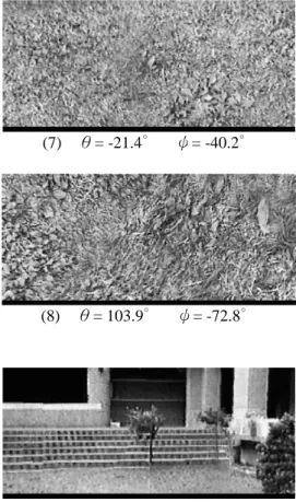
Fig.5 Rendered results when the viewpoint is at the center of the sphere-like polyhedron
X axis ý
ð
(1) ð= 0Hÿ= 0H (2) ð= 41.7H ÿ= 0.6H (3) ð= 36.7H ÿ= 18.1H (4) ð= -11.0H ÿ= 37.4H (5) ð= -11.6H ÿ= 80.1H (6) ð= -27.4H ÿ= -12.3H (7) ð= -21.4H ÿ= -40.2H (8) ð= 103.9H ÿ= -72.8H
Fig.6 Rendered image when the viewpoint of figure 5-(1) is moved 1/3 "radius" (distance from the center of the sphere-like polyhedron to any face) away from the center of the polyhedron
Fig.7 Rendered image when the viewing direction of Fig.6 is turned 45 degrees away from the original direction