Specification for RFID Air Interface
EPC™ Radio-Frequency Identity Protocols
Class-1 Generation-2 UHF RFID
Protocol for Communications at 860 MHz – 960 MHz
Version 1.1.0
right notice
Copy
© 2004, 2005, 2006, EPCglobal Inc.
Unauthorized reproduction, modification and/or use of this Specification is prohibited. Any reproduction, modifi-cation and/or use of this Specifimodifi-cation is subject to the licensing obligations of the EPCglobal Intellectual Prop-erty Policy and enforcement of the terms thereof.
Requests for permission to reproduce should be addressed to [email protected].
Contents
INDEX OF FIGURES ...5 INDEX OF TABLES ...6 FOREWORD ...8 INTRODUCTION ...9 1. SCOPE...10 2. CONFORMANCE ...10 2.1 CLAIMING CONFORMANCE...102.2 GENERAL CONFORMANCE REQUIREMENTS...10
2.2.1 Interrogators ...10
2.2.2 Tags...10
2.3 COMMAND STRUCTURE AND EXTENSIBILITY...11
2.3.1 Mandatory commands ...11
2.3.2 Optional commands...11
2.3.3 Proprietary commands ...11
2.3.4 Custom commands...11
3. NORMATIVE REFERENCES ...11
4. TERMS AND DEFINITIONS ...13
4.1 ADDITIONAL TERMS AND DEFINITIONS...13
5. SYMBOLS, ABBREVIATED TERMS, AND NOTATION...15
5.1 SYMBOLS...15 5.2 ABBREVIATED TERMS...15 5.3 NOTATION...16 6. PROTOCOL REQUIREMENTS...17 6.1 PROTOCOL OVERVIEW...17 6.1.1 Physical layer...17 6.1.2 Tag-identification layer ...17 6.2 PROTOCOL PARAMETERS...17
6.2.1 Signaling – Physical and media access control (MAC) parameters...17
6.2.2 Logical – Operating procedure parameters...21
6.3 DESCRIPTION OF OPERATING PROCEDURE...22
6.3.1 Signaling ...22
6.3.1.1 Operational frequencies ...22
6.3.1.2 Interrogator-to-Tag (R=>T) communications...22
6.3.1.2.1 Interrogator frequency accuracy ...22
6.3.1.2.2 Modulation ...22
6.3.1.2.3 Data encoding...22
6.3.1.2.4 Tari values ...23
6.3.1.2.5 R=>T RF envelope...23
6.3.1.2.6 Interrogator power-up waveform...23
6.3.1.2.7 Interrogator power-down waveform...23
6.3.1.2.8 R=>T preamble and frame-sync ...24
6.3.1.2.9 Frequency-hopping spread-spectrum waveform ...25
6.3.1.2.10Frequency-hopping spread-spectrum channelization...25
6.3.1.2.11Transmit mask ...25 6.3.1.3 Tag-to-Interrogator (T=>R) communications...27 6.3.1.3.1 Modulation ...27 6.3.1.3.2 Data encoding...27 6.3.1.3.2.1 FM0 baseband...28 6.3.1.3.2.2 FM0 preamble ...28 6.3.1.3.2.3 Miller-modulated subcarrier...29
6.3.1.3.2.4 Miller subcarrier preamble...30
6.3.1.3.3 Tag supported Tari values and backscatter link rates ...32
6.3.1.3.5 Minimum operating field strength and backscatter strength...32
6.3.1.4 Transmission order...33
6.3.1.5 Cyclic-redundancy check (CRC) ...33
6.3.1.6 Link timing ...33
6.3.2 Tag selection, inventory, and access ...35
6.3.2.1 Tag memory ...35 6.3.2.1.1 Reserved Memory...36 6.3.2.1.1.1 Kill password ...36 6.3.2.1.1.2 Access password...36 6.3.2.1.2 EPC Memory...36 6.3.2.1.2.1 CRC-16...36 6.3.2.1.2.2 Protocol-control (PC) bits ...36
6.3.2.1.2.3 EPC for an EPCglobal™ Application...37
6.3.2.1.2.4 EPC for a non-EPCglobal™ Application ...37
6.3.2.1.3 TID Memory ...37
6.3.2.1.4 User Memory ...37
6.3.2.1.4.1 User memory for an EPCglobal™ Application ...37
6.3.2.1.4.2 User memory for a non-EPCglobal™ Application ...37
6.3.2.2 Sessions and inventoried flags...38
6.3.2.3 Selected flag...38
6.3.2.4 Tag states and slot counter ...39
6.3.2.4.1 Ready state...39 6.3.2.4.2 Arbitrate state...40 6.3.2.4.3 Reply state ...40 6.3.2.4.4 Acknowledged state...40 6.3.2.4.5 Open state ...40 6.3.2.4.6 Secured state...40 6.3.2.4.7 Killed state ...40 6.3.2.4.8 Slot counter...41
6.3.2.5 Tag random or pseudo-random number generator...41
6.3.2.6 Managing Tag populations ...43
6.3.2.7 Selecting Tag populations ...43
6.3.2.8 Inventorying Tag populations ...43
6.3.2.9 Accessing individual Tags ...45
6.3.2.10 Interrogator commands and Tag replies ...47
6.3.2.10.1Select commands ...49 6.3.2.10.1.1Select (mandatory) ...49 6.3.2.10.2Inventory commands ...51 6.3.2.10.2.1Query (mandatory) ...51 6.3.2.10.2.2QueryAdjust (mandatory) ...52 6.3.2.10.2.3QueryRep (mandatory)...53 6.3.2.10.2.4ACK (mandatory)...54 6.3.2.10.2.5NAK (mandatory)...55 6.3.2.10.3Access commands...56 6.3.2.10.3.1Req_RN (mandatory) ...57 6.3.2.10.3.2Read (mandatory)...58 6.3.2.10.3.3Write (mandatory)...59 6.3.2.10.3.4Kill (mandatory) ...60 6.3.2.10.3.5Lock (mandatory)...63 6.3.2.10.3.6Access (optional) ...65 6.3.2.10.3.7BlockWrite (optional) ...67 6.3.2.10.3.8BlockErase (optional) ...68
7. INTELLECTUAL PROPERTY RIGHTS INTRINSIC TO THIS SPECIFICATION ...69
ANNEX A (NORMATIVE) EXTENSIBLE BIT VECTORS (EBV) ...70
ANNEX B (NORMATIVE) STATE-TRANSITION TABLES ...71
B.1 PRESENT STATE:READY...71
B.2 PRESENT STATE:ARBITRATE...72
B.4 PRESENT STATE:ACKNOWLEDGED...74
B.5 PRESENT STATE:OPEN...75
B.6 PRESENT STATE:SECURED...76
B.7 PRESENT STATE:KILLED...77
ANNEX C (NORMATIVE) COMMAND-RESPONSE TABLES ...78
C.1 COMMAND RESPONSE:POWER-UP...78
C.2 COMMAND RESPONSE:QUERY...78
C.3 COMMAND RESPONSE:QUERYREP...79
C.4 COMMAND RESPONSE:QUERYADJUST...79
C.5 COMMAND RESPONSE:ACK...79
C.6 COMMAND RESPONSE:NAK...80
C.7 COMMAND RESPONSE:REQ_RN...80
C.8 COMMAND RESPONSE:SELECT...80
C.9 COMMAND RESPONSE:READ...81
C.10 COMMAND RESPONSE:WRITE...81
C.11 COMMAND RESPONSE:KILL...82
C.12 COMMAND RESPONSE:LOCK...82
C.13 COMMAND RESPONSE:ACCESS...83
C.14 COMMAND RESPONSE:BLOCKWRITE...83
C.15 COMMAND RESPONSE:BLOCKERASE...84
C.16 COMMAND RESPONSE:T2 TIMEOUT...84
C.17 COMMAND RESPONSE:INVALID COMMAND...85
ANNEX D (INFORMATIVE) EXAMPLE SLOT-COUNT (Q) SELECTION ALGORITHM...86
D.1 EXAMPLE ALGORITHM AN INTERROGATOR MIGHT USE TO CHOOSE Q...86
ANNEX E (INFORMATIVE) EXAMPLE OF TAG INVENTORY AND ACCESS ...87
E.1 EXAMPLE INVENTORY AND ACCESS OF A SINGLE TAG...87
ANNEX F (INFORMATIVE) CALCULATION OF 5-BIT AND 16-BIT CYCLIC REDUNDANCY CHECKS...88
F.1 EXAMPLE CRC-5 ENCODER/DECODER...88
F.2 EXAMPLE CRC-16 ENCODER/DECODER...88
F.3 EXAMPLE CRC-16 CALCULATIONS...89
ANNEX G (NORMATIVE) MULTIPLE- AND DENSE-INTERROGATOR CHANNELIZED SIGNALING...90
G.1 DENSE-INTERROGATOR MODE...90
G.1.1 EXAMPLES OF DENSE-INTERROGATOR-MODE OPERATION (INFORMATIVE) ...90
G.2 CHANNELIZATION IN MULTIPLE- AND DENSE-INTERROGATOR ENVIRONMENTS...91
G.2.1 EXAMPLE CHANNELIZATION (INFORMATIVE) ...91
ANNEX H (INFORMATIVE) INTERROGATOR-TO-TAG LINK MODULATION ...94
H.1 BASEBAND WAVEFORMS, MODULATED RF, AND DETECTED WAVEFORMS...94
ANNEX I (NORMATIVE) ERROR CODES...95
I.1 TAG ERROR CODES AND THEIR USAGE...95
ANNEX J (NORMATIVE) SLOT COUNTER ...96
J.1 SLOT-COUNTER OPERATION...96
ANNEX K (INFORMATIVE) EXAMPLE DATA-FLOW EXCHANGE ...97
K.1 OVERVIEW OF THE DATA-FLOW EXCHANGE...97
K.2 TAG MEMORY CONTENTS AND LOCK-FIELD VALUES...97
K.3 DATA-FLOW EXCHANGE AND COMMAND SEQUENCE...98
ANNEX L (INFORMATIVE) OPTIONAL TAG FEATURES ...99
L.1 OPTIONAL TAG PASSWORDS...99
L.2 OPTIONAL TAG MEMORY BANKS AND MEMORY-BANK SIZES...99
L.3 OPTIONAL TAG COMMANDS...99
L.4 OPTIONAL TAG ERROR-CODE REPORTING FORMAT...99
L.5 OPTIONAL TAG BACKSCATTER MODULATION FORMAT...99
Index of Figures
FIGURE 6.1–PIE SYMBOLS...22
FIGURE 6.2–INTERROGATOR-TO-TAG RF ENVELOPE...23
FIGURE 6.3–INTERROGATOR POWER-UP AND POWER-DOWN RF ENVELOPE...24
FIGURE 6.4–R=>T PREAMBLE AND FRAME-SYNC...25
FIGURE 6.5–FHSSINTERROGATOR RF ENVELOPE...26
FIGURE 6.6–TRANSMIT MASK FOR MULTIPLE-INTERROGATOR ENVIRONMENTS...27
FIGURE 6.7–TRANSMIT MASK FOR DENSE-INTERROGATOR ENVIRONMENTS...27
FIGURE 6.8–FM0 BASIS FUNCTIONS AND GENERATOR STATE DIAGRAM...28
FIGURE 6.9–FM0 SYMBOLS AND SEQUENCES...28
FIGURE 6.10–TERMINATING FM0 TRANSMISSIONS...29
FIGURE 6.11–FM0T=>R PREAMBLE...29
FIGURE 6.12–MILLER BASIS FUNCTIONS AND GENERATOR STATE DIAGRAM...29
FIGURE 6.13–SUBCARRIER SEQUENCES...30
FIGURE 6.14–TERMINATING SUBCARRIER TRANSMISSIONS...31
FIGURE 6.15–SUBCARRIER T=>R PREAMBLE...31
FIGURE 6.16–LINK TIMING...34
FIGURE 6.17–LOGICAL MEMORY MAP...35
FIGURE 6.18–SESSION DIAGRAM...39
FIGURE 6.19–TAG STATE DIAGRAM...42
FIGURE 6.20–INTERROGATOR/TAG OPERATIONS AND TAG STATE...43
FIGURE 6.21–ONE TAG REPLY...45
FIGURE 6.22–SUCCESSFUL WRITE SEQUENCE...59
FIGURE 6.23–KILL PROCEDURE...62
FIGURE 6.24–LOCK PAYLOAD AND USAGE...64
FIGURE 6.25–ACCESS PROCEDURE...66
FIGURE D.1–EXAMPLE ALGORITHM FOR CHOOSING THE SLOT-COUNT PARAMETER Q...86
FIGURE E.1–EXAMPLE OF TAG INVENTORY AND ACCESS...87
FIGURE F.1–EXAMPLE CRC-5 CIRCUIT...88
FIGURE F.2–EXAMPLE CRC-16 CIRCUIT...89
FIGURE G.1–ALGORITHM FOR DETERMINING CHANNELIZATION AND DENSE-INTERROGATOR-MODE PARAMETERS...91
FIGURE G.2–EXAMPLES OF DENSE-INTERROGATOR-MODE OPERATION...92
FIGURE G.3–CHANNEL NUMBERING FOR EXAMPLE 3 ...93
FIGURE H.1–INTERROGATOR-TO-TAG MODULATION...94
Index of Tables
TABLE 6.1–INTERROGATOR-TO-TAG (R=>T) COMMUNICATIONS...18
TABLE 6.2–TAG-TO-INTERROGATOR (T=>R) COMMUNICATIONS...19
TABLE 6.3–TAG INVENTORY AND ACCESS PARAMETERS...21
TABLE 6.4–COLLISION MANAGEMENT PARAMETERS...21
TABLE 6.5–RF ENVELOPE PARAMETERS...23
TABLE 6.6–INTERROGATOR POWER-UP WAVEFORM PARAMETERS...24
TABLE 6.7–INTERROGATOR POWER-DOWN WAVEFORM PARAMETERS...24
TABLE 6.8–FHSS WAVEFORM PARAMETERS...26
TABLE 6.9–TAG-TO-INTERROGATOR LINK FREQUENCIES...32
TABLE 6.10–TAG-TO-INTERROGATOR DATA RATES...32
TABLE 6.11–CRC-16 PRECURSOR...33
TABLE 6.12–CRC-5 DEFINITION.SEE ALSO ANNEX F ...33
TABLE 6.13–LINK TIMING PARAMETERS...34
TABLE 6.14–TAG FLAGS AND PERSISTENCE VALUES...39
TABLE 6.15–ACCESS COMMANDS AND TAG STATES IN WHICH THEY ARE PERMITTED...46
TABLE 6.16–COMMANDS...48
TABLE 6.17–SELECT COMMAND...50
TABLE 6.18–TAG RESPONSE TO ACTION PARAMETER...50
TABLE 6.19–QUERY COMMAND...51
TABLE 6.20–TAG REPLY TO A QUERY COMMAND...51
TABLE 6.21–QUERYADJUST COMMAND...52
TABLE 6.22–TAG REPLY TO A QUERYADJUST COMMAND...52
TABLE 6.23–QUERYREP COMMAND...53
TABLE 6.24–TAG REPLY TO A QUERYREP COMMAND...53
TABLE 6.25–ACK COMMAND...54
TABLE 6.26–TAG REPLY TO A SUCCESSFUL ACK COMMAND...54
TABLE 6.27–NAK COMMAND...55
TABLE 6.28–REQ_RN COMMAND...57
TABLE 6.29–TAG REPLY TO A REQ_RN COMMAND...57
TABLE 6.30–READ COMMAND...58
TABLE 6.31–TAG REPLY TO A SUCCESSFUL READ COMMAND...58
TABLE 6.32–WRITE COMMAND...59
TABLE 6.33–TAG REPLY TO A SUCCESSFUL WRITE COMMAND...59
TABLE 6.34–KILL COMMAND...61
TABLE 6.35–TAG REPLY TO THE FIRST KILL COMMAND...61
TABLE 6.36–TAG REPLY TO A SUCCESSFUL KILL PROCEDURE...61
TABLE 6.37–LOCK COMMAND...64
TABLE 6.38–TAG REPLY TO A LOCK COMMAND...64
TABLE 6.39–LOCKACTION-FIELD FUNCTIONALITY...64
TABLE 6.40–ACCESS COMMAND...65
TABLE 6.41–TAG REPLY TO AN ACCESS COMMAND...65
TABLE 6.42–BLOCKWRITE COMMAND...67
TABLE 6.43–TAG REPLY TO A SUCCESSFUL BLOCKWRITE COMMAND...67
TABLE 6.44–BLOCKERASE COMMAND...68
TABLE 6.45–TAG REPLY TO A SUCCESSFUL BLOCKERASE COMMAND...68
TABLE A.1–EBV-8 WORD FORMAT...70
TABLE B.1–READY STATE-TRANSITION TABLE...71
TABLE B.2–ARBITRATE STATE-TRANSITION TABLE...72
TABLE B.3–REPLY STATE-TRANSITION TABLE...73
TABLE B.4–ACKNOWLEDGED STATE-TRANSITION TABLE...74
TABLE B.5–OPEN STATE-TRANSITION TABLE...75
TABLE B.6–SECURED STATE-TRANSITION TABLE...76
TABLE B.7–KILLED STATE-TRANSITION TABLE...77
TABLE C.1–POWER-UP COMMAND-RESPONSE TABLE...78
TABLE C.2–QUERY1 COMMAND-RESPONSE TABLE...78
TABLE C.4–QUERYADJUST1 COMMAND-RESPONSE TABLE2...79
TABLE C.5–ACK COMMAND-RESPONSE TABLE...79
TABLE C.6–NAK COMMAND-RESPONSE TABLE...80
TABLE C.7–REQ_RN COMMAND-RESPONSE TABLE...80
TABLE C.8–SELECT COMMAND-RESPONSE TABLE...80
TABLE C.9–READ COMMAND-RESPONSE TABLE...81
TABLE C.10–WRITE COMMAND-RESPONSE TABLE...81
TABLE C.11–KILL1 COMMAND-RESPONSE TABLE...82
TABLE C.12–LOCK COMMAND-RESPONSE TABLE...82
TABLE C.13–ACCESS1 COMMAND-RESPONSE TABLE...83
TABLE C.14–BLOCKWRITE COMMAND-RESPONSE TABLE...83
TABLE C.15–BLOCKERASE COMMAND-RESPONSE TABLE...84
TABLE C.16–T2 TIMEOUT COMMAND-RESPONSE TABLE...84
TABLE C.17–INVALID COMMAND-RESPONSE TABLE...85
TABLE F.1–CRC-5 REGISTER PRELOAD VALUES...88
TABLE F.2–EPC MEMORY CONTENTS FOR AN EXAMPLE TAG...89
TABLE G.1–CHANNELIZATION FOR EXAMPLE 2 ...93
TABLE I.1–TAG-ERROR REPLY FORMAT...95
TABLE I.2–TAG ERROR CODES...95
TABLE K.1–TAG MEMORY CONTENTS...97
TABLE K.2–LOCK-FIELD VALUES...97
TABLE K.3–INTERROGATOR COMMANDS AND TAG REPLIES...98
Foreword
This specification defines the base class (Class-1) of four radio-frequency identification (RFID) Tag classes. The class structure is described as follows:
Class-1: Identity Tags (normative)
Passive-backscatter Tags with the following minimum features:
• An electronic product code (EPC) identifier,
• A Tag identifier (Tag ID),
• A 'kill' function that permanently disables the Tag,
• Optional password-protected access control, and
• Optional user memory.
Class restrictions (normative)
Class-2, Class-3, Class-4, or higher class Tags shall not conflict with the operation of, nor degrade the perform-ance of, Class-1 Tags located in the same RF environment.
Higher-class Tags (informative)
The following class descriptions provide an example of how higher-class Tag features might be delineated: Class-2: Higher-Functionality Tags
Passive Tags with the following anticipated features above and beyond those of Class-1 Tags:
• An extended Tag ID,
• Extended user memory,
• Authenticated access control, and
• Additional features (TBD) as will be defined in the Class-2 specification. Class-3: Semi-Passive Tags
Semi-passive Tags with the following anticipated features above and beyond those of Class-2 Tags:
• An integral power source, and
• Integrated sensing circuitry. Class-4: Active Tags
Active Tags with the following anticipated features above and beyond those of Class-3 Tags:
• Tag-to-Tag communications,
• Active communications, and
Introduction
This specification defines the physical and logical requirements for a passive-backscatter, Interrogator-talks-first (ITF), radio-frequency identification (RFID) system operating in the 860 MHz – 960 MHz frequency range. The system comprises Interrogators, also known as Readers, and Tags, also known as Labels.
An Interrogator transmits information to a Tag by modulating an RF signal in the 860 MHz – 960 MHz frequency range. The Tag receives both information and operating energy from this RF signal. Tags are passive, meaning that they receive all of their operating energy from the Interrogator’s RF waveform.
An Interrogator receives information from a Tag by transmitting a continuous-wave (CW) RF signal to the Tag; the Tag responds by modulating the reflection coefficient of its antenna, thereby backscattering an information signal to the Interrogator. The system is ITF, meaning that a Tag modulates its antenna reflection coefficient with an in-formation signal only after being directed to do so by an Interrogator.
Interrogators and Tags are not required to talk simultaneously; rather, communications are half-duplex, meaning that Interrogators talk and Tags listen, or vice versa.
1. Scope
This document specifies:
• Physical interactions (the signaling layer of the communication link) between Interrogators and Tags,
• Interrogator and Tag operating procedures and commands, and
• The collision arbitration scheme used to identify a specific Tag in a multiple-Tag environment.
2. Conformance
2.1 Claiming conformance
A device shall not claim conformance with this specification unless the device complies with a) all clauses in this specification (except those marked as optional), and
b) the conformance document associated with this specification, and, c) all local radio regulations.
Conformance may also require a license from the owner of any intellectual property utilized by said device.
2.2 General conformance requirements
2.2.1 Interrogators
To conform to this specification, an Interrogator shall:
• Meet the requirements of this specification,
• Implement the mandatory commands defined in this specification,
• Modulate/transmit and receive/demodulate a sufficient set of the electrical signals defined in the signaling layer of this specification to communicate with conformant Tags, and
• Conform to all local radio regulations. To conform to this specification, an Interrogator may:
• Implement any subset of the optional commands defined in this specification, and
• Implement any proprietary and/or custom commands in conformance with this specification. To conform to this specification, an Interrogator shall not:
• Implement any command that conflicts with this specification, or
• Require using an optional, proprietary, or custom command to meet the requirements of this specification.
2.2.2 Tags
To conform to this specification, a Tag shall:
• Meet the requirements of this specification,
• Operate over the frequency range from 860 – 960 MHz, inclusive,
• Implement the mandatory commands defined in this specification,
• Modulate a backscatter signal only after receiving the requisite command from an Interrogator, and
• Conform to all local radio regulations. To conform to this specification, a Tag may:
• Implement any subset of the optional commands defined in this specification, and
• Implement any proprietary and/or custom commands as defined in 2.3.3 and 2.3.4, respectively. To conform to this specification, a Tag shall not:
• Require using an optional, proprietary, or custom command to meet the requirements of this specification, or
• Modulate a backscatter signal unless commanded to do so by an Interrogator using the signaling layer defined in this specification.
2.3 Command structure and extensibility
This specification allows four command types: (1) mandatory, (2) optional, (3) proprietary, and (4) custom. Subclause 6.3.2.10 and Table 6.16 define the structure of the command codes used by Interrogators and Tags for each of the four types, as well as the availability of future extensions.
All commands defined by this specification are either mandatory or optional. Proprietary or custom commands are vendor-defined.
2.3.1 Mandatory commands
Conforming Tags shall support all mandatory commands. Conforming Interrogators shall support all manda-tory commands.
2.3.2 Optional commands
Conforming Tags may or may not support optional commands. Conforming Interrogators may or may not support optional commands. If a Tag or an Interrogator implements an optional command, it shall implement it in the manner specified in this specification.
2.3.3 Proprietary commands
Proprietary commands may be enabled in conformance with this specification, but are not specified herein. All proprietary commands shall be capable of being permanently disabled. Proprietary commands are in-tended for manufacturing purposes and shall not be used in field-deployed RFID systems.
2.3.4 Custom commands
Custom commands may be enabled in conformance with this specification, but are not specified herein. An Interrogator shall issue a custom command only after (i) singulating a Tag, and (ii) reading (or having prior knowledge of) the Tag manufacturer’s identification in the Tag’s TID memory. An Interrogator shall use a custom command only in accordance with the specifications of the Tag manufacturer identified in the Tag ID. A custom command shall not solely duplicate the functionality of any mandatory or optional command defined in this specification by a different method.
3. Normative references
The following referenced documents are indispensable to the application of this specification. For dated references, only the edition cited applies. For undated references, the latest edition (including any amendments) applies.
EPCglobal™: EPC™ Tag Data Standards (versions 1.3 and above) EPCglobal™ (2004): FMCG RFID Physical Requirements Document (draft) EPCglobal™: Class-1 Generation-2 UHF RFID Implementation Reference (draft)
European Telecommunications Standards Institute (ETSI), EN 300 220 (all parts): Electromagnetic compatibility and Radio spectrum Matters (ERM); Short Range Devices (SRD); Radio equipment to be used in the 25 MHz to 1000 MHz frequency range with power levels ranging up to 500 mW
European Telecommunications Standards Institute (ETSI), EN 302 208: Electromagnetic compatibility and radio spectrum matters (ERM) – Radio-frequency identification equipment operating in the band 865 MHz to 868 MHz with power levels up to 2 W, Part 1 – Technical characteristics and test methods
European Telecommunications Standards Institute (ETSI), EN 302 208: Electromagnetic compatibility and radio spectrum matters (ERM) – Radio-frequency identification equipment operating in the band 865 MHz to 868 MHz with power levels up to 2 W, Part 2 – Harmonized EN under article 3.2 of the R&TTE directive
ISO/IEC Directives, Part 2: Rules for the structure and drafting of International Standards
ISO/IEC 3309: Information technology – Telecommunications and information exchange between systems –
High-level data link control (HDLC) procedures – Frame structure
ISO/IEC 15961: Information technology, Automatic identification and data capture – Radio frequency identification (RFID) for item management – Data protocol: application interface
ISO/IEC 15962: Information technology, Automatic identification and data capture techniques – Radio frequency identification (RFID) for item management – Data protocol: data encoding rules and logical memory functions
ISO/IEC 15963: Information technology — Radiofrequency identification for item management — Unique identifi-cation for RF tags
ISO/IEC 18000-1: Information technology — Radio frequency identification for item management — Part 1: Ref-erence architecture and definition of parameters to be standardized
ISO/IEC 18000-6: Information technology automatic identification and data capture techniques — Radio fre-quency identification for item management air interface — Part 6: Parameters for air interface communications at 860–960 MHz
ISO/IEC 19762: Information technology AIDC techniques – Harmonized vocabulary – Part 3: radio-frequency identification (RFID)
U.S. Code of Federal Regulations (CFR), Title 47, Chapter I, Part 15: Radio-frequency devices, U.S. Federal Communications Commission
4. Terms and definitions
The principal terms and definitions used in this specification are described in ISO/IEC 19762.
4.1 Additional terms and definitions
Terms and definitions specific to this document that supersede any normative references are as follows:
• Air interface
The complete communication link between an Interrogator and a Tag including the physical layer, collision ar-bitration algorithm, command and response structure, and data-coding methodology.
• Command set
The set of commands used to explore and modify a Tag population.
• Continuous wave
Typically a sinusoid at a given frequency, but more generally any Interrogator waveform suitable for powering a passive Tag without amplitude and/or phase modulation of sufficient magnitude to be interpreted by a Tag as transmitted data.
• Cover-coding
A method by which an Interrogator obscures information that it is transmitting to a Tag. To cover-code data or a password, an Interrogator first requests a random number from the Tag. The Interrogator then performs a bit-wise EXOR of the data or password with this random number, and transmits the cover-coded (also called ciphertext) string to the Tag. The Tag uncovers the data or password by performing a bit-wise EXOR of the received cover-coded string with the original random number.
• Dense-Interrogator environment
An operating environment (defined below) within which most or all of the available channels are occupied by active Interrogators (for example, 25 active Interrogators operating in 25 available channels).
• Dense-Interrogator mode
A set of Interrogator-to-Tag and Tag-to-Interrogator signaling parameters used in dense-Interrogator envi-ronments.
• Extended temperature range
–40 °C to +65 °C (see nominal temperature range).
• EPCglobal™ Application
An application whose usage denotes an acceptance of EPCglobal™ standards and policies (see non-EPCglobal™ Application).
• Full-duplex communications
A communications channel that carries data in both directions at once. See also half-duplex communications.
• Half-duplex communications
A communications channel that carries data in one direction at a time rather than in both directions at once. See also full-duplex communications.
• Inventoried flag
A flag that indicates whether a Tag may respond to an Interrogator. Tags maintain a separate inventoried flag for each of four sessions; each flag has symmetric A and B values. Within any given session,
Interroga-tors typically inventory Tags from A to B followed by a re-inventory of Tags from B back to A (or vice versa).
• Inventory round
The period initiated by a Query command and terminated by either a subsequent Query command (which
also starts a new inventory round) or a Select command.
• Multiple-Interrogator environment
An operating environment (defined below) within which a modest number of the available channels are occu-pied by active Interrogators (for example, 5 active Interrogators operating in 25 available channels).
• Nominal temperature range
–25 °C to +40 °C (see extended temperature range).
• Non-EPCglobal™ Application
An application whose usage does not denote an acceptance of EPCglobal™ standards and policies (see EP-Cglobal™ Application).
• Operating environment
A region within which an Interrogator’s RF transmissions are attenuated by less than 90dB. In free space, the operating environment is a sphere whose radius is approximately 1000m, with the Interrogator located at the center. In a building or other enclosure, the size and shape of the operating environment depends on factors such as the material properties and shape of the building, and may be less than 1000m in certain directions and greater than 1000m in other directions.
• Operating procedure
Collectively, the set of functions and commands used by an Interrogator to identify and modify Tags. (Also known as the Tag-identification layer.)
• Passive Tag (or passive Label)
A Tag (or Label) whose transceiver is powered by the RF field.
• Permalock or Permalocked
A memory location whose lock status is unchangeable (i.e. the memory location is permanently locked or per-manently unlocked) is said to be permalocked.
• Persistent memory or persistent flag
A memory or flag value whose state is maintained during a brief loss of Tag power.
• Physical layer
The data coding and modulation waveforms used in Interrogator-to-Tag and Tag-to-Interrogator signaling.
• Protocol
Collectively, a physical layer and a Tag-identification layer specification.
• Q
A parameter that an Interrogator uses to regulate the probability of Tag response. An Interrogator commands Tags in an inventory round to load a Q-bit random (or pseudo-random) number into their slot counter; the
In-terrogator may also command Tags to decrement their slot counter. Tags reply when the value in their slot counter (i.e. their slot – see below) is zero. Q is an integer in the range (0,15); the corresponding
Tag-response probabilities range from 20 = 1 to 2–15 = 0.000031.
• Random-slotted collision arbitration
A collision-arbitration algorithm where Tags load a random (or pseudo-random) number into a slot counter, decrement this slot counter based on Interrogator commands, and reply to the Interrogator when their slot counter reaches zero.
• Session
An inventory process comprising an Interrogator and an associated Tag population. An Interrogator chooses one of four sessions and inventories Tags within that session. The Interrogator and associated Tag population operate in one and only one session for the duration of an inventory round (defined above). For each session, Tags maintain a corresponding inventoried flag. Sessions allow Tags to keep track of their inventoried status separately for each of four possible time-interleaved inventory processes, using an independent inventoried flag for each process.
• Single-Interrogator environment
An operating environment (defined above) within which there is a single active Interrogator at any given time.
• Singulation
• Slot
Slot corresponds to the point in an inventory round at which a Tag may respond. Slot is the value output by a Tag’s slot counter; Tags reply when their slot (i.e. the value in their slot counter) is zero. See also Q (above).
• Tag-identification layer
Collectively, the set of functions and commands used by an Interrogator to identify and modify Tags (also known as the operating procedure).
• Tari
Reference time interval for a data-0 in Interrogator-to-Tag signaling. The mnemonic “Tari” derives from the ISO/IEC 18000-6 (part A) specification, in which Tari is an abbreviation for Type A Reference Interval.
5. Symbols, abbreviated terms, and notation
The principal symbols and abbreviated terms used in this specification are detailed in ISO/IEC 19762, Information technology AIDC techniques – vocabulary. Symbols, abbreviated terms, and notation specific to this document
are as follows:
5.1 Symbols
BLF Backscatter-link frequency (BLF = 1/Tpri = DR/TRcal)
DR Divide ratio
FT Frequency tolerance
Mh RF signal envelope ripple (overshoot)
Mhh FHSS signal envelope ripple (overshoot)
Ml RF signal envelope ripple (undershoot)
Mhl FHSS signal envelope ripple (undershoot)
Ms RF signal level when OFF
Mhs FHSS signal level during a hop
Q Slot-count parameter
R=>T Interrogator-to-Tag
RTcal Interrogator-to-Tag calibration symbol
T1 Time from Interrogator transmission to Tag response
T2 Time from Tag response to Interrogator transmission
T3 Time an Interrogator waits, after T1, before it issues another command
T4 Minimum time between Interrogator commands
Tf or Tf,10-90% RF signal envelope fall time
Thf FHSS signal envelope fall time
Thr FHSS signal envelope rise time
Ths Time for an FHSS signal to settle to within a specified percentage of its final value
Tpri Backscatter-link pulse-repetition interval (Tpri = 1/BLF = TRcal/DR)
Tr or Tr,10-90% RF signal envelope rise time
Ts Time for an RF signal to settle to within a specified percentage of its final value
T=>R Tag-to-Interrogator
TRcal Tag-to-Interrogator calibration symbol
xfp floating-point value
xxxx2 binary notation
xxxxh hexadecimal notation
5.2 Abbreviated terms
AFI Application family identifier
ASK Amplitude shift keying
CEPT Conference of European Posts and Telecommunications
Ciphertext Information that is cover-coded
CRC Cyclic redundancy check
CW Continuous wave
dBch Decibels referenced to the integrated power in the reference channel
DSB Double sideband
DSB-ASK Double-sideband amplitude-shift keying
EPC Electronic product code
ETSI European Telecommunications Standards Institute
FCC Federal Communications Commission
FDM Frequency-Division Multiplexing
FHSS Frequency-hopping spread spectrum
Handle 16-bit Tag-authentication number NSI Numbering system identifier PIE Pulse-interval encoding
Pivot Decision threshold differentiating an R=>T data-0 symbol from a data-1 symbol Plaintext Information that is not cover-coded
ppm Parts-per-million
PSK Phase shift keying or phase shift keyed PR-ASK Phase-reversal amplitude shift keying
RF Radio frequency
RFID Radio-frequency identification
RFU Reserved for future use
RN16 16-bit random or pseudo-random number
RNG Random or pseudo-random number generator
ITF Interrogator talks first (reader talks first)
SSB Single sideband
SSB-ASK Single-sideband amplitude-shift keying
TDM Time-division multiplexing or time-division multiplexed (as appropriate)
Tag ID Tag-identification or Tag identifier, depending on context
Word 16 bits
5.3 Notation
This specification uses the following notational conventions:
• States and flags are denoted in bold. Example: ready.
• Commands are denoted in italics. Variables are also denoted in italics. Where there might be confusion between commands and variables, this specification will make an explicit statement. Example: Query.
• Command parameters are underlined. Example: Pointer.
• For logical negation, labels are preceded by ‘~’. Example: If flag is true, then ~flag is false.
• The symbol, R=>T, refers to commands or signaling from an Interrogator to a Tag (Reader-to-Tag).
6. Protocol requirements
6.1 Protocol overview
6.1.1 Physical layer
An Interrogator sends information to one or more Tags by modulating an RF carrier using double-sideband ampli-tude shift keying (DSB-ASK), single-sideband ampliampli-tude shift keying (SSB-ASK), or phase-reversal ampliampli-tude shift keying (PR-ASK) using a pulse-interval encoding (PIE) format. Tags receive their operating energy from this same modulated RF carrier.
An Interrogator receives information from a Tag by transmitting an unmodulated RF carrier and listening for a backscattered reply. Tags communicate information by backscatter modulating the amplitude and/or phase of the RF carrier. The encoding format, selected in response to Interrogator commands, is either FM0 or Miller-modulated subcarrier. The communications link between Interrogators and Tags is half-duplex, meaning that Tags shall not be required to demodulate Interrogator commands while backscattering. A Tag shall not respond to a mandatory or optional command using full-duplex communications.
6.1.2 Tag-identification layer
An Interrogator manages Tag populations using three basic operations:
a) Select. The operation of choosing a Tag population for inventory and access. A Select command may be
applied successively to select a particular Tag population based on user-specified criteria. This operation is analogous to selecting records from a database.
b) Inventory. The operation of identifying Tags. An Interrogator begins an inventory round by transmitting a
Query command in one of four sessions. One or more Tags may reply. The Interrogator detects a single
Tag reply and requests the PC, EPC, and CRC-16 from the Tag. Inventory comprises multiple com-mands. An inventory round operates in one and only one session at a time.
c) Access. The operation of communicating with (reading from and/or writing to) a Tag. An individual Tag must be uniquely identified prior to access. Access comprises multiple commands, some of which employ one-time-pad based cover-coding of the R=>T link.
6.2 Protocol parameters
6.2.1 Signaling – Physical and media access control (MAC) parameters
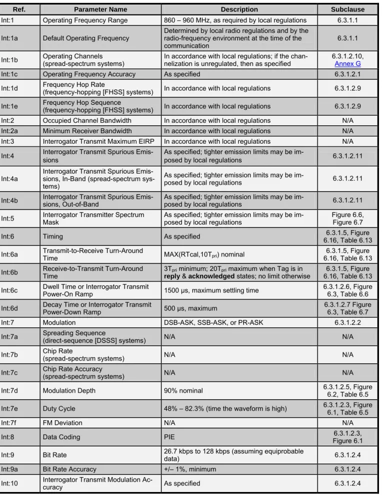
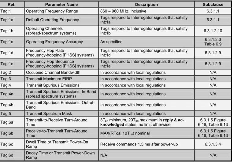
Table 6.1 and Table 6.2 provide an overview of parameters for R=>T and T=>R communications according to this specification; for detailed requirements refer to the referenced Subclause. For those parameters that do not apply to or are not used in this specification, the notation “N/A” shall indicate that the parameter is “Not Applicable”.
Table 6.1 – Interrogator-to-Tag (R=>T) communications
Ref. Parameter Name Description Subclause
Int:1 Operating Frequency Range 860 – 960 MHz, as required by local regulations 6.3.1.1
Int:1a Default Operating Frequency Determined by local radio regulations and by the radio-frequency environment at the time of the
communication 6.3.1.1
Int:1b Operating Channels (spread-spectrum systems) In accordance with local regulations; if the chan-nelization is unregulated, then as specified 6.3.1.2.10, Annex G
Int:1c Operating Frequency Accuracy As specified 6.3.1.2.1
Int:1d Frequency Hop Rate (frequency-hopping [FHSS] systems) In accordance with local regulations 6.3.1.2.9 Int:1e Frequency Hop Sequence (frequency-hopping [FHSS] systems) In accordance with local regulations 6.3.1.2.9
Int:2 Occupied Channel Bandwidth In accordance with local regulations N/A
Int:2a Minimum Receiver Bandwidth In accordance with local regulations N/A
Int:3 Interrogator Transmit Maximum EIRP In accordance with local regulations N/A
Int:4 Interrogator Transmit Spurious Emis-sions
As specified; tighter emission limits may be
im-posed by local regulations 6.3.1.2.11
Int:4a Interrogator Transmit Spurious Emis-sions, In-Band (spread-spectrum sys-tems)
As specified; tighter emission limits may be
im-posed by local regulations 6.3.1.2.11
Int:4b Interrogator Transmit Spurious Emis-sions, Out-of-Band As specified; tighter emission limits may be im-posed by local regulations 6.3.1.2.11 Int:5 Interrogator Transmitter Spectrum Mask As specified; tighter emission limits may be im-posed by local regulations Figure 6.6, Figure 6.7
Int:6 Timing As specified 6.16, Table 6.13 6.3.1.5, Figure
Int:6a Transmit-to-Receive Turn-Around Time MAX(RTcal,10Tpri) nominal 6.16, Table 6.13 6.3.1.5, Figure
Int:6b Receive-to-Transmit Turn-Around Time 3Tpri minimum; 20Tpri maximum when Tag is in reply & acknowledged states; no limit otherwise
6.3.1.5, Figure 6.16, Table 6.13 Int:6c Dwell Time or Interrogator Transmit Power-On Ramp 1500 µs, maximum settling time 6.3.1.2.6, Figure 6.3, Table 6.6 Int:6d Decay Time or Interrogator Transmit Power-Down Ramp 500 µs, maximum 6.3.1.2.7 Figure 6.3, Table 6.7
Int:7 Modulation DSB-ASK, SSB-ASK, or PR-ASK 6.3.1.2.2
Int:7a Spreading Sequence (direct-sequence [DSSS] systems) N/A N/A
Int:7b Chip Rate (spread-spectrum systems) N/A N/A
Int:7c Chip Rate Accuracy (spread-spectrum systems) N/A N/A
Int:7d Modulation Depth 90% nominal 6.3.1.2.5, Figure 6.2, Table 6.5
Int:7e Duty Cycle 48% – 82.3% (time the waveform is high) 6.3.1.2.3, Figure 6.1, Table 6.5
Int:7f FM Deviation N/A N/A
Int:8 Data Coding PIE Figure 6.1 6.3.1.2.3,
Int:9 Bit Rate 26.7 kbps to 128 kbps (assuming equiprobable data) 6.3.1.2.4
Int:9a Bit Rate Accuracy +/– 1%, minimum 6.3.1.2.4
Ref. Parameter Name Description Subclause
Int:11 Preamble Required 6.3.1.2.8
Int:11a Preamble Length As specified 6.3.1.2.8
Int:11b Preamble Waveform(s) As specified Figure 6.4
Int:11c Bit Sync Sequence None N/A
Int:11d Frame Sync Sequence Required Figure 6.4 6.3.1.2.8,
Int:12 Scrambling (spread-spectrum sys-tems) N/A N/A
Int:13 Bit Transmission Order MSB is transmitted first 6.3.1.4
Int:14 Wake-up process As specified 6.3.1.3.4
Int:15 Polarization Not specified N/A
Table 6.2 – Tag-to-Interrogator (T=>R) communications
Ref. Parameter Name Description Subclause
Tag:1 Operating Frequency Range 860 – 960 MHz, inclusive 6.3.1.1
Tag:1a Default Operating Frequency Tags respond to Interrogator signals that satisfy Int:1a 6.3.1.1 Tag:1b Operating Channels (spread-spectrum systems) Tags respond to Interrogator signals that satisfy Int:1b 6.3.1.2.10
Tag:1c Operating Frequency Accuracy As specified Table 6.9 6.3.1.3.3
Tag:1d Frequency Hop Rate (frequency-hopping [FHSS] systems) Tags respond to Interrogator signals that satisfy Int:1d 6.3.1.2.9 Tag:1e Frequency Hop Sequence (frequency-hopping [FHSS] systems) Tags respond to Interrogator signals that satisfy Int:1e 6.3.1.2.9
Tag:2 Occupied Channel Bandwidth In accordance with local regulations N/A
Tag:3 Transmit Maximum EIRP In accordance with local regulations N/A
Tag:4 Transmit Spurious Emissions In accordance with local regulations N/A
Tag:4a Transmit Spurious Emissions, In-Band(spread spectrum systems) In accordance with local regulations N/A Tag:4b Transmit Spurious Emissions, Out-of-Band In accordance with local regulations N/A
Tag:5 Transmit Spectrum Mask In accordance with local regulations N/A
Tag:6a Transmit-to-Receive Turn-Around Time 3Tpri minimum, 20Tpri maximum in reply & ac-knowledged states; no limit otherwise
6.3.1.5 Figure 6.16, Table 6.13 Tag:6b Receive-to-Transmit Turn-Around Time MAX(RTcal,10Tpri) nominal 6.16, Table 6.13 6.3.1.5 Figure
Tag:6c Dwell Time or Transmit Power-On Ramp Receive commands 1.5 ms after power-up 6.3.1.3.4
Ref. Parameter Name Description Subclause
Tag:7 Modulation ASK and/or PSK modulation (selected by Tag) 6.3.1.3.1
Tag:7a Spreading Sequence (direct sequence [DSSS] systems) N/A N/A
Tag:7b Chip Rate (spread spectrum systems) N/A N/A
Tag:7c Chip Rate Accuracy (spread spectrum systems) N/A N/A
Tag:7d On-Off Ratio Not specified N/A
Tag:7e Subcarrier Frequency 40 kHz to 640 kHz Table 6.9 6.3.1.3.3
Tag:7f Subcarrier Frequency Accuracy As specified Table 6.9
Tag:7g Subcarrier Modulation Miller, at the data rate Figure 6.13 6.3.1.3.2.3,
Tag:7h Duty Cycle FM0: 50%, nominal Subcarrier: 50%, nominal 6.3.1.3.2.1, 6.3.1.3.2.3
Tag:7I FM Deviation N/A N/A
Tag:8 Data Coding Baseband FM0 or Miller-modulated subcarrier (selected by the Interrogator) 6.3.1.3.2 Tag:9 Bit Rate FM0: 40 kbps to 640 kbps Subcarrier modulated: 5 kbps to 320 kbps Table 6.9 6.3.1.3.3 Tag:9a Bit Rate Accuracy Same as Subcarrier Frequency Accuracy; see Tag:7f 6.3.1.3.3, Table 6.9, Table 6.10
Tag:10 Tag Transmit Modulation Accuracy (frequency-hopping [FHSS] systems N/A N/A
Tag:11 Preamble Required 6.3.1.3.2.2, 6.3.1.3.2.4
Tag:11a Preamble Length As specified Figure 6.11, Figure 6.15
Tag:11b Preamble Waveform As specified Figure 6.11, Figure 6.15
Tag:11c Bit-Sync Sequence None N/A
Tag:11d Frame-Sync Sequence None N/A
Tag:12 Scrambling (spread-spectrum systems) N/A N/A
Tag:13 Bit Transmission Order MSB is transmitted first 6.3.1.4
Tag:14 Reserved Deliberately left blank N/A
Tag:15 Polarization Tag dependent; not specified by this document N/A
6.2.2 Logical – Operating procedure parameters
Table 6.3 and Table 6.4 identify and describe parameters used by an Interrogator during the selection, inventory, and access of Tags according to this specification. For those parameters that do not apply to or are not used in this specification, the notation “N/A” shall indicate that the parameter is “Not Applicable”.
Table 6.3 – Tag inventory and access parameters
Ref. Parameter Name Description Subclause
P:1 Who talks first Interrogator 6.3
P:2 Tag addressing capability As specified 6.3.2.1
P:3 Tag EPC Contained in Tag memory 6.3.2.1
P:3a EPC Length As specified 6.3.2.1.2.2
P:3b EPC Format
NSI < 100h: As specified in EPCglobal™ Tag
Data Standards (version 1.3 and above),
NSI ≥ 100h: As specified in ISO/IEC 15961
6.3.2.1.2.2 6.3.2.1.2.3 6.3.2.1.2.4
P:4 Read size Multiples of 16 bits 6.3.2.10.3.2 Table 6.30
P:5 Write Size Multiples of 16 bits
6.3.2.10.3.3, Table 6.32, 6.3.2.10.3.7,
Table 6.42 P:6 Read Transaction Time Varied with R=>T and T=>R link rate and number of bits being read 6.3.2.10.3.2
P:7 Write Transaction Time 20 ms (maximum) after end of Write command
6.3.2.10.3.3, 6.3.2.10.3.7, Figure 6.22 P:8 Error detection Interrogator-to-Tag: Select command: CRC-16 Query command: CRC-5
Other Inventory commands: Command length Access commands: CRC-16
Tag-to-Interrogator: PC, EPC: CRC-16
RN16: None or CRC-16 (varies with command) handle: CRC-16
All other: CRC-16
6.3.2.10 and its subsections
P:9 Error correction None N/A
P:10 Memory size Tag dependent, extensible (size is neither limited nor specified by this document) N/A
P:11 Command structure and extensibility As specified Table 6.16
Table 6.4 – Collision management parameters
Ref. Parameter Name Description Subclause
A:1 Type (Probabilistic or Deterministic) Probabilistic 6.3.2.6
A:2 Linearity Linear up to 2
15 Tags in the Interrogator’s RF
field; above that number, NlogN for Tags with unique EPCs
6.3.2.8
6.3 Description of operating procedure
The operating procedure defines the physical and logical requirements for an Interrogator-talks-first (ITF), ran-dom-slotted collision arbitration, RFID system operating in the 860 MHz – 960 MHz frequency range.
6.3.1 Signaling
The signaling interface between an Interrogator and a Tag may be viewed as the physical layer in a layered net-work communication system. The signaling interface defines frequencies, modulation, data coding, RF envelope, data rates, and other parameters required for RF communications.
6.3.1.1 Operational frequencies
Tags shall receive power from and communicate with Interrogators within the frequency range from 860 MHz to 960 MHz, inclusive. An Interrogator’s choice of operational frequency will be determined by local radio regulations and by the local radio-frequency environment. Interrogators certified for operation in dense-Interrogator environ-ments shall support, but are not required to always use, the optional dense-Interrogator mode described in Annex G.
6.3.1.2 Interrogator-to-Tag (R=>T) communications
An Interrogator communicates with one or more Tags by modulating an RF carrier using DSB-ASK, SSB-ASK, or PR-ASK with PIE encoding. Interrogators shall use a fixed modulation format and data rate for the duration of an inventory round, where “inventory round” is defined in 4.1. The Interrogator sets the data rate by means of the preamble that initiates the round.
The high values in Figure 6.1, Figure 6.2, Figure 6.3, Figure 6.4, and Figure 6.5, correspond to emitted CW (i.e. an Interrogator delivering power to the Tag or Tags) whereas the low values correspond to attenuated CW. 6.3.1.2.1 Interrogator frequency accuracy
Interrogators certified for operation in single- or multiple-Interrogator environments shall have a frequency accu-racy that meets local regulations. Interrogators certified for operation in dense-Interrogator environments shall have a frequency accuracy of +/– 10 ppm over the nominal temperature range (–25 °C to +40 °C) and +/– 20 ppm over the extended temperature range (–40°C to +65°C) while transmitting, unless local regulations specify tighter accuracy, in which case the Interrogator frequency accuracy shall meet the local regulations.
6.3.1.2.2 Modulation
Interrogators shall communicate using DSB-ASK, SSB-ASK, or PR-ASK modulation, detailed in Annex H. Tags shall demodulate all three modulation types.
6.3.1.2.3 Data encoding
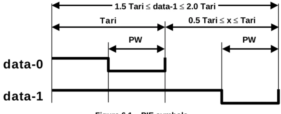
The R=>T link shall use PIE, shown in Figure 6.1. Tari is the reference time interval for Interrogator-to-Tag signal-ing, and is the duration of a data-0. High values represent transmitted CW; low values represent attenuated CW. Pulse modulation depth, rise time, fall time, and PW shall be as specified in Table 6.5, and shall be the same for a data-0 and a data-1. Interrogators shall use a fixed modulation depth, rise time, fall time, PW, Tari, data-0 length, and data-1 length for the duration of an inventory round. The RF envelope shall be as specified in Figure 6.2.
data-0
data-1
Tari 0.5 Tari ≤ x ≤ Tari
PW 1.5 Tari ≤ data-1 ≤ 2.0 Tari
PW
6.3.1.2.4 Tari values
Interrogators shall communicate using Tari values in the range of 6.25µs to 25µs. Interrogator compliance shall be evaluated using at least one Tari value between 6.25µs and 25µs with at least one value of the parameter x. The tolerance on all parameters specified in units of Tari shall be +/–1%. The choice of Tari value and x shall be in accordance with local radio regulations.
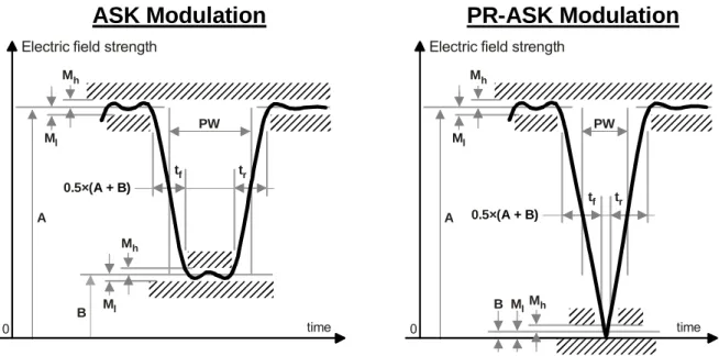
6.3.1.2.5 R=>T RF envelope
The R=>T RF envelope shall comply with Figure 6.2 and Table 6.5. The electric field strength A is the maximum amplitude of the RF envelope. Tari is defined in Figure 6.1. The pulsewidth is measured at the 50% point on the pulse. An Interrogator shall not change the R=>T modulation type (i.e. shall not switch between DSB-ASK, SSB-ASK, or PR-ASK) without first powering down its RF waveform (see 6.3.1.2.7).
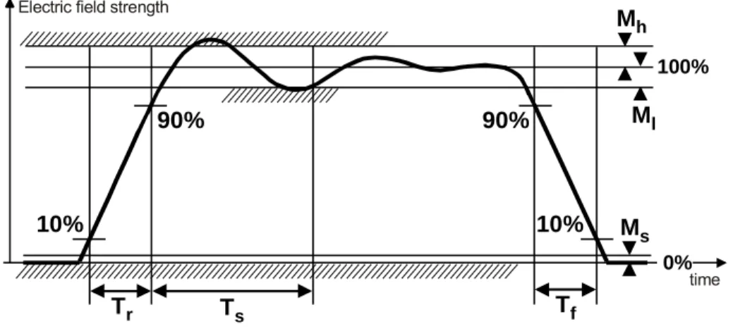
6.3.1.2.6 Interrogator power-up waveform
The Interrogator power-up RF envelope shall comply with Figure 6.3 and Table 6.6. Once the carrier level has risen above the 10% level, the power-up envelope shall rise monotonically until at least the ripple limit Ml. The RF
envelope shall not fall below the 90% point in Figure 6.3 during interval Ts. Interrogators shall not issue
com-mands before the end of the maximum settling-time interval in Table 6.6 (i.e. before Ts). 6.3.1.2.7 Interrogator power-down waveform
The Interrogator power-down RF envelope shall comply with Figure 6.3 and Table 6.7. Once the carrier level has fallen below the 90% level, the power-down envelope shall fall monotonically until the power-off limit Ms. Once
powered off, an Interrogator shall remain powered off for a least 1ms before powering up again.
Electric field strength
0 time tf tr Ml Mh A Ml Mh B PW 0.5×(A + B)
Electric field strength
0 time tf tr Ml Mh A MlMh B PW 0.5×(A + B)
ASK Modulation
PR-ASK Modulation
Figure 6.2 – Interrogator-to-Tag RF envelope Table 6.5 – RF envelope parameters
Tari Parameter Symbol Minimum Nominal Maximum Units
Modulation Depth (A–B)/A 80 90 100 %
RF Envelope Ripple Mh = Ml 0 0.05(A–B) V/m
RF Envelope Rise Time tr,10–90% 0 0.33Tari µs
RF Envelope Fall Time tf,10–90% 0 0.33Tari µs
6.25 µs to 25 µs
100% 0% Tr Ts Mh Ml Ms Tf 10% 90% 90% 10%
Electric field strength
time
Figure 6.3 – Interrogator power-up and power-down RF envelope Table 6.6 – Interrogator power-up waveform parameters
Parameter Definition Minimum Nominal Maximum Units
Tr Rise time 1 500 µs
Ts Settling time 1500 µs
Ms Signal level when OFF 1 % full scale
Ml Undershoot 5 % full scale
Mh Overshoot 5 % full scale
Table 6.7 – Interrogator power-down waveform parameters
Parameter Definition Minimum Nominal Maximum Units
Tf Fall time 1 500 µs
Ms Signal level when OFF 1 % full scale
Ml Undershoot 5 % full scale
Mh Overshoot 5 % full scale
6.3.1.2.8 R=>T preamble and frame-sync
An t Figure round shall b A prea and •
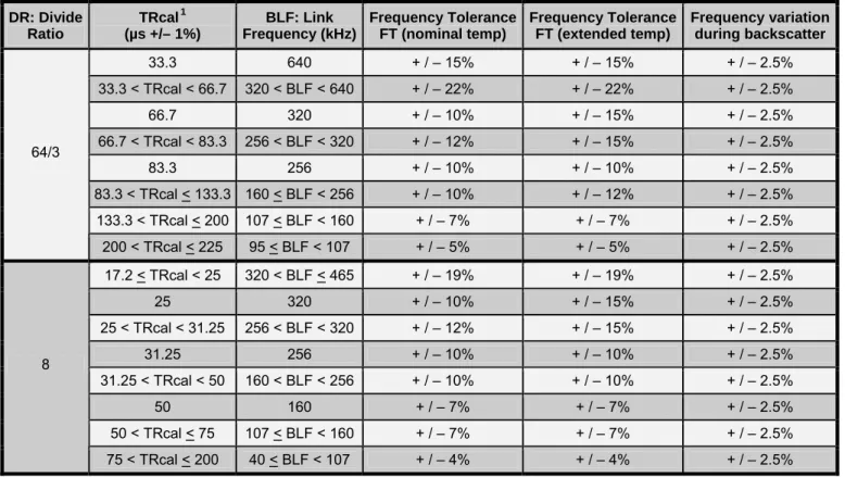
• TRcal: An Interrogator shall specify a Tag’s backscatter link freq of its Miller subcarrier) using the TRcal and divide ratio (DR) in the
F, and In errogator shall begin all R=>T signaling with either a preamble or a frame-sync, both of which are shown in 6.4. A preamble shall precede a Query command (see 6.3.2.10.2.1) and denotes the start of an inventory
. All other signaling shall begin with a frame-sync. The tolerance on all parameters specified in units of Tari e +/–1%. PW shall be as specified in Table 6.5. The RF envelope shall be as specified in Figure 6.2.
mble shall comprise a fixed-length start delimiter, a data-0 symbol, an R=>T calibration (RTcal) symbol, a T=>R calibration (TRcal) symbol.
RTcal: An Interrogator shall set RTcal equal to the length of a data-0 symbol plus the length of a data-1 symbol (RTcal = 0length + 1length). A Tag shall measure the length of RTcal and compute pivot = RTcal / 2.
The Tag shall interpret subsequent Interrogator symbols shorter than pivot to be data-0s, and subsequent
Interrogator symbols longer than pivot to be data-1s. The Tag shall interpret symbols longer than 4 RTcal
to be bad data. Prior to changing RTcal, an Interrogator shall transmit CW for a minimum of 8 RTcal. uency (its FM0 datarate or the frequency
preamble and payload, respectively, of a
Query command that initiates an inventory round. Equation (1) specifies the relationship between the
adjust its T=>R link rate to be equal to BLF (Table 6.9 shows BLF values and tolerances). The TRcal and RTcal that an Interrogator uses in any inventory round shall meet the constraints in Equation (2):
= DR
BLF
TRcal (1)
1.1 RTcal TRcal 3 RTcal× ≤ ≤ × (2)
A frame-sync is identical to a preamble, minus the TRcal symbol. An Interrogator, for the duration of an inventory he preamble that initiated the round.
before the end of the maximum settling-time interval in Table 6.8 (i.e. before T ). The maximum time between frequency hops and the minimum RF-off time during a hop
uirements.
cas
round, shall use the same length RTcal in a frame-sync as it used in t 6.3.1.2.9 Frequency-hopping spread-spectrum waveform
When an Interrogator uses frequency-hopping spread spectrum (FHSS) signaling, the Interrogator’s RF envelope shall comply with Figure 6.5 and Table 6.8. The RF envelope shall not fall below the 90% point in Figure 6.5 dur-ing interval Ths. Interrogators shall not issue commands
hs
shall meet local regulatory req
6.3.1.2.10 Frequency-hopping spread-spectrum channelization
Interrogators certified for operation in single-Interrogator environments shall meet local regulations for spread-spectrum channelization. Interrogators certified for operation in multiple- or dense-Interrogator environments shall meet local regulations for spread-spectrum channelization, unless the channelization is unregulated, in which e Interrogators shall adopt the channelization described by the algorithm in Figure G.1 (Annex G describes tiple- and dense-Interrogator channelized signaling).
mul 6.3.1.2.
Interrog rotocol shall meet local regulations for out-of-channel and
out-of-b
Interrog ator environments, in addition to meeting local regulations,
shall also meet the Multiple-Interrogator Transmit Mask defined in this specification:
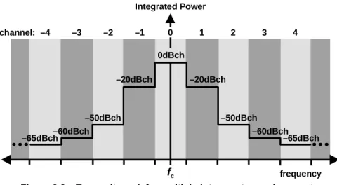
Multiple-Interrogator Transmit Mask: For an Interrogator transmitting random data in channel R, and any
other channel S≠R, the ratio of the integrated power P() in channel S to that in channel R shall not exceed the
specified values:
• |R – S| = 1: 10log10(P(S) / P(R)) < –20 dB 11 Transmit mask
ators certified for operation according to this p and spurious radio-frequency emissions. ators certified for operation in multiple-Interrog
12.5µs +/
delim – 5%
R=>T calibration (RTcal) iter
1.1RTcal ≤ TRcal ≤ 3 RTcal PW
T=>R calibration (TRcal) PW
2.5 Tari ≤ RTcal ≤ 3.0 Tari 1 Tari PW data-0 12.5µs +/– 5% R=>T calibration (RTcal) delimiter PW 2.5 Tari ≤ RTcal ≤ 3.0 Tari 1 Tari
PW
data-0
R=>T Preamble
R=>T Frame-Sync
• |R – S| = 2: 10log10(P(S) / P(R)) < –50 dB
• |R – S| = 3: 10log10(P(S) / P(R)) < –60 dB
• |R – S| > 3: 10log10(P(S) / P(R)) < –65 dB
Wh annel. This mask is shown graphically in
ng in the optional dense-Interrogator mod
ere P() denotes the total integrated power in the specified ch
re 6.6, with dBch defined as dB referenced to the integrated
Figu power in the reference channel. For any
transmit channel R, two exceptions to the mask are permitted, provided that
• neither exception exceeds –50 dBch, and
• neither exception exceeds local regulatory requirements.
An exception occurs when the integrated power in a channel S exceeds the mask. Each channel that exceeds
the mask shall be counted as an exception.
Interrogators certified for operation in dense-Interrogator environments shall meet both local regulations and the Transmit Mask shown in Figure 6.6 of this specification, except when operati
e described in Annex G, in which case they shall instead meet the Dense-Interrogator Transmit Mask de-bed below and shown in Figure 6.7. Regardless of the mask used, Interrogators certified for operation in se-Interrogator environments shall not be permitted the two exceptions to the transmit mask that are allowed Interrogators certified for operation in multiple-Interrogato
scri den
for r environments.
Den - ator transmissions centered at a frequency fc, a 2.5/Tari
ban cy fo = 2.5/Tari, and a 2.5/Tari bandwidth SBW centered at
(n × ) + wer P() in SBW to that in RBW with the Interrogator
transmit-ting n es:
10 BW BW
• | n| > 2: 10log10(P(SBW) / P(RBW)) < –65 dB
Where P() denotes the total integrated power in the 2.5/Tari reference bandwidth. This mask is shown graphi-cally in Figure 6.7, with dBch defined as dB referenced to the integrated power in the reference channel.
se Interrogator Transmit Mask: For Interrog dwidth RBW also centered at fc, an offset frequen
), the e in
fo fc (integer n ratio of th tegrated po
ra dom data shall not exceed the specified valu
• | n| = 1: 10log10(P(SBW) / P(RBW)) < –30 dB • | n| = 2: 10log (P(S ) / P(R )) < –60 dB 100% 0% Thr Ths Mhh Mhl Mhs Thf 10% 90% 90% 10%
Electric field strength
time
Figure 6.5 – FHSS Interrogator RF envelope Table 6.8 – FHSS waveform parameters
Parameter Definition Minimum Nominal Maximum Units
Thr Rise time 500 µs
Ths Settling time 1500 µs
Thf Fall time 500 µs
Mhs Signal level during hop 1 % full scale
Mhl Undershoot 5 % full scale
Integrated Power
6.3.1.3 Tag-to-Interrogator (T=>R) communications
A Tag communicates with an Interrogator using backscatter modulation, in which the Tag switches the reflection coefficient of its antenna between two states in accordance with the data being sent.
a fixed modulation format, data encoding, and data rate for the duration of an
inven-ery command that initiates the round. The low values in
Figure 6.9, Figure 6.10, Figure 6.11, Figure 6.13, Figure 6.14, and Figure 6.15 correspond to the antenna-reflectivity state the Tag exhibits during the CW period prior to a T=>R preamble (e.g. ASK Tag absorbing power), whereas the high values correspond to the antenna-reflectivity state the Tag exhibits during the first high pulse of a T=>R preamble (e.g. ASK Tag reflecting power).
6.3.1.3.1 Modulation
Tag backscatter shall use ASK and/or PSK modulation. The Tag vendor selects the modulation format. Interroga-tors shall demodulate both modulation types.
6.3.1.3.2 Data encoding
Tags shall encode the backscattered data as either FM0 baseband or Miller modulation of a subcarrier at the data rate. The Interrogator commands the encoding choice.
A Tag shall backscatter using
tory round, where “inventory round” is defined in 6.3.2.8. The Tag selects the modulation format; the Interrogator selects the encoding and data rate by means of the Qu
fc channel: 1 2 0dBch 0 3 4 –4 –3 –2 –1 –20dBch –20dBch frequency –50dBch –50dBch –60dBch –60dBch –65dBch –65dBch
Figure 6.6 – Transmit mask for multiple-Interrogator environments
Integrated Power fc frequency 0dBch –30dBch –30dBch –60dBch –60dBch –65dBch –65dBch –1.25 Tari 1.25 Tari 3.75 Tari 6.25 Tari –3.75 Tari –6.25 Tari 8.75 Tari –8.75 Tari
6.3.1.3.2.1 FM0 baseband
Figure 6.8 shows basis functions and a state diagram for gen inverts
the baseband phase at every symbol boundary; a data-0 has an additional mid-symbol phase inversion. The state logical data sequence to the FM0 basis functions that are transmitted. The state
memory; consequently, the choice of FM0 sequences in Figure 6.9 depends on prior
ling shall begin with one of the two preambles shown in Figure 6.11. The choice depends on the value of the TRext bit specified in the Query command that initiated the inventory round, unless a Tag is replying
emory, in which case a Tag shall use the extended preamble regardless of TRext erating FM0 (bi-phase space) encoding. FM0
diagram in Figure 6.8 maps a
labels, S1–S4, indicate four possible FM0-encoded symbols, represented by the two phases of each of the FM0
basis functions. The state labels also represent the FM0 waveform that is transmitted upon entering the state. The labels on the state transitions indicate the logical values of the data sequence to be encoded. For example, a transition from state S2 to S3 is disallowed because the resulting transmission would not have a phase inversion
on a symbol boundary.
Figure 6.9 shows generated baseband FM0 symbols and sequences. The duty cycle of a 00 or 11 sequence, measured at the modulator output, shall be a minimum of 45% and a maximum of 55%, with a nominal value of 50%. FM0 encoding has
transmissions. FM0 signaling shall always end with a “dummy” data-1 bit at the end of a transmission, as shown in Figure 6.10.
6.3.1.3.2.2 FM0 preamble T=>R FM0 signa
to a command that writes to m
(i.e. the Tag replies as if TRext=1 regardless of the TRext value specified in the Query—see 6.3.2.10.3). The “v”
shown in Figure 6.11 indicates an FM0 violation (i.e. a phase inversion should have occurred but did not).
FM0 Generator State Diagram FM0 Basis Functions S2 S3 S1 S4 0 1 0 1 0 1 1 time (t) 1 0 T data-1 s4(t) = –s1(t) s1(t) 1 –1 0 T data-0 s3(t) = –s2(t) s2(t) time (t) 0 ampl it ud e
Figure 6.8 – FM0 basis functions and generator state diagram
1 0 1 00 01 10 11 00 01 10 11 FM0 Symbols FM0 Sequences
Figure 6.9 – FM0 symbols and sequences
FM0 End-of-Signaling 0 0 1 dummy 1 dummy 1 dummy 1 dummy 1 1
Figure 6.10 – Terminating FM0 transmissions
1 0 1 0 v 1 FM0 Preamble (TRext = 0) 12 leading zero 0 0 s (pilot tone) 1 0 1 0 v 1 FM0 Preamble (TRext = 1) 0 0 Figure 6.11 – FM0 T=>R preamble 6.3.1.3.2.3 Miller-modulated subcarrier
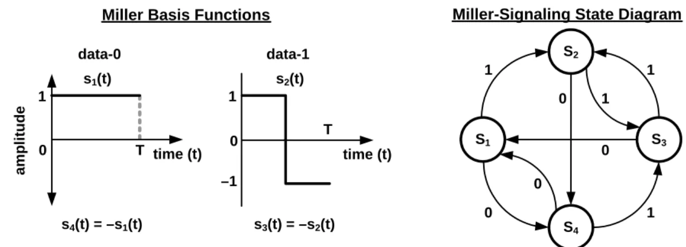
Figure 6.12 shows basis functions and a state diagram for generating Miller encoding. Baseband Miller inverts its phase between two data-0s in sequence. Baseband Miller also places a phase inversion in the middle of a data-1 symbol. The state diagram in Figure 6.12 maps a logical data sequence to baseband Miller basis functions. The state labels, S1–S4, indicate four possible Miller-encoded symbols, represented by the two phases of each of the
Miller basis functions. The state labels also represent the baseband Miller waveform that is generated upon enter-ing the state. The transmitted waveform is the baseband waveform multiplied by a square-wave at M times the symbol rate. The labels on the state transitions indicate the logical values of the data sequence to be encoded. For example, a transition from state S1 to S3 is disallowed because the resulting transmission would have a phase
inversion on a symbol boundary between a data-0 and a data-1.
S2 S3 S1 S4 1 0 1 1 0 0 0 1
Miller-Signaling State Diagram Miller Basis Functions
1 –1 0 T data-1 s3(t) = –s2(t) s2(t) time (t) time (t) 1 0 T data-0 s4(t) = –s1(t) s1(t) amp litude
Figure 6.13 shows Miller-modulated subcarrier sequences; the Miller sequence shall contain exactly two, four, or eight subcarrier cycles per bit, depending on the M value specified in the Query command that initiated the
inven-tory round (see Table 6.10). The d odulator output, shall be a
minimum of 45% and a maximum of 55%, with a nominal value of 50%. Miller encoding has memory;
conse-6.3.1.3.2.4 Miller subcarrier preamble
h one of the two preambles shown in Figure 6.15. The choice depends uty cycle of a 0 or 1 symbol, measured at the m
quently, the choice of Miller sequences in Figure 6.13 depends on prior transmissions. Miller signaling shall al-ways end with a “dummy” data-1 bit at the end of a transmission, as shown in Figure 6.14.
T=>R subcarrier signaling shall begin wit
on the value of the TRext bit specified in the Query command that initiated the inventory round, unless a Tag is
replying to a command that writes to memory, in which case a Tag shall use the extended preamble regardless of TRext (i.e. the Tag replies as if TRext=1 regardless of the TRext value specified in the Query—see 6.3.2.10.3).