security DesiGN for the opeN site
5
5.1
iNtroDuctioN
t
he main characteristic of an open site, as referred to in this publica-tion, is that it provides significant space for vehicular and pedestrian circulation, parking, and other site related functions between the site perimeter and the project building or buildings. An open site is usu-ally located in a suburban, rural, or semi-rural area. A campus is a large open site that accommodates a multi-building facility, such as a college or university, a medical center, a governmental agency, a private industrial or commercial park, or any similar group of facilities.The security design implications for the open site include aspects such as the amount of land available on the site for stand-off and the inherent ability of the site to accommodate the implementation of security design features. It is important to recognize that conflicts sometimes emerge be-tween security design elements and conventional site design. For example, open circulation and common spaces (which are desirable for conven-tional design) may be detrimental to certain aspects of security. Designers must balance good design practices with protection priorities.
The central concept when adopting elements of protection is to fulfill the security objectives without disruption to other site requirements. Indeed, the aim should be to adopt security elements that as far as possible pro-vide opportunities to enhance the project overall. The project design should offer an attractive approach to the site and to the building(s), with a clear hierarchy of entry experiences, and at the same time provide func-tional site services.
This chapter describes security protection for an open site in which build-ings that are potential targets are located. It begins by depicting the main elements applicable to the layers of defense, access points, control-of-vehicle angles of approach, gatehouses, and screening; it follows by discussing the security implications of general site design tasks, such as signage, parking, loading docks and service access, physical security lighting, and site utilities.
5.2 LAyers of DefeNse for the opeN
site
The general "layers of defense" concept presupposes a spacious site with a vehicular approach to the defended building (see Chapter 3).
The defended perimeter may or may not be on the site property line. Each site needs to be evaluated to determine the location and types of barriers for the protected area. Typically, the barrier designates the stand-off distance around the building. If possible, this should not be less than the minimum recommended, and if the site permits, it may be considerably more. Intelligence gathering in this layer of defense is im-portant, and cameras and sensors should be installed at entrances and around the perimeter.
Figure 5-1 shows the whole site as an exclusive protected area; the perim-eter barrier is located on the property line. In the example shown, the on-site parking is within the second layer of defense. Crash-rated elements are used where the site is vulnerable to invasive vehicles. The diagram assumes that the rear of the site is impassible to vehicles; the barrier is lim-ited to a fence to deter intruders, although this could also be a crash-rated barrier. Generous stand-off distances can often be easily achieved.
Figure 5-1:
Protective barrier located on the property line, to provide required stand-off, with on-site parking within the protected area.
Layers of defense for a campus may take several forms, depending on the threat level for the campus as a whole and the threat level posed by indi-vidual buildings. The campus in Figure 5-3 shows that in addition to the typical first line of defense outside the property, much of the site may also assume the roles of first and second lines of defense outside a fully pro-tected perimeter, for one or more higher-risk buildings.
In this example, the campus may have open access, as in an industrial park, and individual buildings may have varying protection, from min-imal access control to the full three levels of defense around a high-risk building. In this latter case the rest of the campus becomes part of the first and second defense layer for the high-risk building. Other variations of campus protection are:
m The campus may have limited access control, as in a university that
controls access, providing information and parking permits at entry points and a degree of security against normal criminal activity. Specific high-risk buildings on campus may also have the full three layers of defense.
Figure 5-2:
Protective barrier located within the site, providing minimum stand-off.
m The whole campus may be a high-risk site, such as a military
installation, a critical industrial facility, or a sensitive government laboratory. This campus would have full perimeter barriers and access control and second layer of defense measures within the perimeter. Some very high-risk individual buildings might also have a third layer of protection provision. Typically, a campus has sufficient acreage to provide the recommended stand-off protection. The exception might be an urban campus in which open space is limited.
The precise mix of campus and building protection must be carefully evaluated to arrive at an integrated defense strategy.
The remaining parts of this section describe the main security ele-ments for an open site. Most of the measures are relevant for high-risk to medium-risk buildings. These security elements can be imple-mented in conjunction with crime protection through environmental design procedures (CPTED). CPTED employs limited physical design
Figure 5-3:
Layers of defense for a campus type site.
SOURCE: U.S. aIR FORCE, installation entry control facilities design guide
5.3
Access coNtroL poiNts
t
he objective of the access point is to prevent unauthorized access, while at the same time controlling the rate of entry for vehicles and pedestrians. An access point is a designated area for autho-rized building users: employees, visitors, and service providers. Access points along the defended perimeter are commonly shared between the first and second layers of defense, providing observation of approach,controlled entry, and queuing areas. Structures such as control booths and equipment such as active barriers, communications, and closed-cir-cuit TV are layered throughout the entry sequence, to provide secured access points. These site features will normally be within the site property line, but the access itself will be from a public roadway and form part of the first defense layer.
Detailed guidance on the design of entry control points is provided in U.S. Navy (NAVFAC) publication ITG 03-03, Interim Technical Guidance (ITG) Entry Control Facilities, Atlantic Division, Norfolk, Virginia.
The location of access control points and inspection areas should be at sufficient stand-off distance that detonation of a bomb on an uninspected vehicle does not impact the closest building and cause lethal damage. Figure 5-4 shows a typical layout of a high-security vehicle entry point and controlled access zone within a protected perimeter.
An issue in the design of the entry control point is the orientation of parking at the visitor center and of vehicles at an inspection location. Due to the fragmentation of the axles and engine block caused by an ex-plosion, parking should not be oriented so that the front or rear of the vehicle is pointed toward a nearby building or guardhouse.
Figure 5-4:
Typical entry control point layout.
SOURCE: US aIR FORCE, installation entry control facilities design guide
Whenever possible, commercial, service and delivery vehicles should have a designated entry point to the site, preferably away from high-risk buildings. Active perimeter entrances should be designated so that security personnel can maintain full control without creating unneces-sary delays. This can be accomplished by the provision of a sufficient number of entry points to accommodate the peak flow of pedestrians and vehicular traffic, as well as adequate lighting for rapid and efficient inspection.
The number of access points into a site should be minimized because they are a potential source of weakness in the controlled perimeter, and they are costly in construction and personnel. However, at least two controlled access points should be provided in case one is shut down by maintenance, bomb squad activity, or other causes.
FEMA 426, Section 2.5, describes a number of measures that should be considered in the design of entry control points. These are all driven by security needs and are important determinants of site planning.
5.4 coNtroL of VehicuLAr ApproAch
speeD
t
he threat of vehicular attack can be reduced significantly by con-trolling vehicular speed and removing the opportunity for direct collision with the building. If the vehicle is forced to slow down and impact a barrier at a shallow angle, the impact forces are reduced, and the barrier can be designed to lower performance requirements. The speed of vehicles can be reduced by designing entry roads tosites and buildings so that they do not provide direct or straight-line access that will enable a vehicle to gather speed as it approaches. Moreover, indirect approaches to a building, together with appropriate landscaping and earth forms, can increase the attractiveness of the ap-proach. Framing the sight of the building by landscaping and other ways of controlling the views of the building can add to the aesthetic experiences of the approach.
Some specific devices and design methods of reducing vehicle speed are:
m Traffic circles m Curved roadways
m Speed bumps and speed tables m Raised crosswalks
m Pavement treatments
m Use of berms, high curbs and trees to prevent vehicles departing the
roadway
Some of these approaches are shown in Figure 5-6.
Speed control approaching gatehouses is also a concern. Some of the devices and design methods listed above can be used when approaching gates. In addition, bollards around the gatehouse can be used to narrow the approach. Truck entrances will require wider lanes that can be handled by either active or removable bollards to limit the opening when trucks are not entering.
Reduction of the opportunity for direct collision can be achieved by en-suring that approach roads do not permit head-on impact. If space allows, approaches should be designed that are parallel to the building façade.
Figure 5-5:
Portion of threat vector study. The objective is to force the vehicle to impact the barrier at reduced speed and at a shallow angle.
5.5
GAtehouses AND security
screeNiNG
G
atehouse and screening require access control with human in-tervention. Design of the entry control point must accomplish many security-related functions to accommodate traffic, control the approach and direction of vehicles, accommodate queuing, andsup-Figure 5-6: Methods of reducing vehicle approach speed. Small Traffic circle
large Traffic circle aT Building enTrance ProvideS indirecT aPProach curved driveway aPProach
5.5.1 GAtehouses
Guidance for the design of some considerations related to gatehouses in-cludes the following:
m Gatehouses should be hardened as determined by the design basis
threat and should provide protection from elements.
m Gatehouses can be part of an important element for delivery and
queuing.
m If ID checking is also required between the traffic lanes, some
measure of protection against hostile activity should be provided.
m Gatehouses, lobbies, and guard posts should be provided with clear
views of approaching traffic, both pedestrian and vehicular.
m Queuing space for pedestrian visitors to gather as they wait to enter a
building is necessary; this may be provided in a screening pavilion for visitors beyond the building entry, which may be at a distance from the main facilities.
m Active vehicle crash barriers are necessary to deny entry and to give
entry control personnel adequate time to respond to unauthorized activities. The response time is defined as the time required for complete activation of the active vehicle barrier once a threat is detected. The response time includes the time for security personnel to react to a threat and initiate the activation of the barrier system, and the time for the selected barrier to fully deploy and close the roadway.
Figures 5-7 and 5-8 show detailed basic layouts for two types of gatehouse and entry barrier systems.
Figure 5-7:
Features of a typical vehicular entry control post, gatehouse at side.
SOURCE: DELTa SCIENTIFIC CORP.
These diagrams show typical metal prefabricated gatehouses. Gatehouses
designed to harmonize with the building architecture present a more
at-tractive image (Figure 5-9)
.Figure 5-9:
Gatehouses should match the architecture. a simple small
building, with fine iron gates, reflects the classical architecture of the main building.
Figure 5-8:
Features of a typical vehicular entry control post, center gatehouse.
SOURCE: DELTa SCIENTIFIC CORP.
5.5.2 sALLy ports
In very high-risk situations, a double row of barriers is used, creating a
sally port. Before 9/11, sally ports were used almost exclusively in
cor-rectional institutions. They consist of an enclosure with two electrically
operated barriers; only one door is allowed to open at any one time.
The first barrier opens only after authorized entry is determined: the
second barrier is opened after the inspection is completed. This
en-sures that a following vehicle cannot “tailgate” the lead vehicle and
obtain entry without screening. Figure 5-10 shows a sally port used for
vehicular entry.
5.5.3 screeNiNG At DesiGNAteD iNspectioN
AreAs
Screening or a designated area of inspection typically starts with an eval-uation of the anticipated demand for access of vehicles that will require inspection. Analyses of traffic origin and destination, the capability of the surrounding road network, including its capacity to handle addi-tional traffic, and the need for possible expansion capacity should then be performed. These analyses should be coordinated with state and local departments of transportation, departments of public works, and law enforcement.
When necessary, inspection areas should be designed to be as incon-spicuous as possible, blending seamlessly into the surrounding context.
Figure 5-10:
Sally port installation with two active barriers. Note NOGO barriers at the sides (see Section 4.6.1).
Appropriate landscape plantings, walls, fences, or creative architectural details can be helpful. Screening of the inspection areas also helps en-sure that inspection procedures are not easily observed. Adequate space should be provided to perform inspection of pedestrians and/or vehicles without interrupting the normal flow of traffic.
When considering access roads and inspections, designers should have in mind the following:
m Approaches to the site should be designed to accommodate peak
traffic demand without impeding traffic flow in the surrounding road network.
m Pull-over lanes at site entry gates should be provided for initial vehicle
check prior to allowing access to a site.
m Holding or containment areas for screening vehicles should be
established outside the secured perimeter that establishes the stand-off distance. The proper placement of these areas is critical to their effectiveness, the functionality of the site, and the overall appearance of the project.
m Inspection areas should be large enough to accommodate a
minimum of one vehicle and a pull-out lane. They should also be covered and capable of accommodating the inspection of the undercarriage plus overhead inspection equipment. Inspection bays that can be closed to protect inspection equipment and staff in the event of bad weather are ideal.
m Parking of vehicles too close to the building should be avoided even
after screening.
m All available inspection technologies (e.g., above-vehicle and
under-vehicle surveillance systems, ion scanning, and x-ray equipment) should be investigated when sizing and designing the inspection areas.
m A separate, sheltered structure for pedestrian visitors may be a good
solution when lobby space is limited. This also moves screening of small package bombs outside the structure (Figures 5-11, 5-12).
For high-security buildings, a final denial barrier after initial screening is necessary to stop unauthorized vehicles from entering the site. Most indi-viduals who attempt to enter without authorization are lost, confused, or inattentive, but there are also those whose intent may be to “run the gate.” A properly designed final denial barrier will take into account both groups,
safely stopping the individuals who have made an honest mistake, but pro-viding a properly designed barrier to stop those with hostile intentions. Final denial barrier placement is based on the activation time for weapon delivery methods and the response time needed for a given scenario. For example, to stop a high-performance vehicle that accelerates from a stop at the ID check, given an 8-second response time, an active barrier should be placed approximately 330 feet from the access control point so that it can close before the vehicle reaches it. (Figure 5-13).
Figure 5-11:
Separate screening pavilion for visitors at building entrance. Well-designed structure blends with other site features and maintains character of surrounding context.
Figure 5-12:
5.6
the site DesiGN tAsKs
t
he fundamental objective of site planning is to establish the placement of buildings, parking areas, and other necessary structures in such a way as to provide a setting that is function-ally effective as well as aestheticfunction-ally pleasing. The need for security adds another dimension to the range of issues that must be consid-ered (Figure 5-14).Figure 5-14:
a well-designed site is both secure and aesthetically pleasing. Custom bollards, trees and seating create a safe and quiet place on a city plaza.
SOURCE: PETER WaLKER aND PaRTNERS
Figure 5-13:
The following aspects of the building program and layout may impact the security design:
m Building footprint(s) relative to total land available. m Building location(s) or, if undeveloped, suitable building
location(s) relative to the site perimeter and adjacent land uses, and the available distance between the defended perimeter and improved areas off-site.
m Overall size and number of the structures to be placed on site. m Massing and placement of buildings that may impact views, sight
lines, and screening.
m Access via foot, road, rail, water, and air.
m Proximity to fire and police stations, hospitals, shelters, and other
critical facilities that could respond to emergency situations.
m Presence of natural physical barriers such as water features, dense
vegetation, and terrain that could provide access control and/or shielding, or suitability of the site for the incorporation of such features.
m Topographic and climatic characteristics that could affect the
performance of chemical agents and other weapons.
m Management of visibility issues from outside site boundaries,
including ensuring that vegetation in proximity to building does not provide the opportunity to screen covert activity.
m Ability to limit the number of access/egress points, such as visitor
entries, staff entries, and loading docks.
m Internal vehicular circulation (driveways, surface parking areas) and
pedestrian circulation (sidewalks, tunnels and bridges).
m Location of uses and operations within the building, such as
high-risk areas that require controlled access and higher levels of security, and their interface with site requirements.
5.6.1 site eVALuAtioN, GrADiNG, AND
DrAiNAGe
In addition to shaping the topography to support buildings and site functions, the site can also be used to control or direct blast away from vulnerable structures and to open or block views. The basic grading re-quirements include developing proper elevations for buildings, parking, and roadways, as well as providing positive drainage, tree preservation, and balanced cut and fill. Security impacts and opportunities include:
m Surface storm water management areas, whether for detention or
retention, that can be designed as site features. Their placement and design could enhance the effectiveness of stand-off zones. Local regulations will define the minimum requirements for these areas. Enhancement may include shaping the basin beyond the storm water management requirements to support appropriate vegetation and wildlife, or providing adjacent walkways and observation areas. Surface water areas may also be designed and placed to limit site access in a discreet manner (Figure 5-15).
m Drainage swales that can be carefully located and designed to prevent
the use of their lower elevations as hiding places.
Figure 5-15:
Run-off from a large factory site creates attractive wetlands: the water provides compelling arrival and departure experiences for visitors and employees. Though not intended as a security barrier, it would limit vehicle access from the threat side of the building.
SOURCE: MICHaEL VaN VaLKENBURGH aSSOCIaTES, INC.
requirements in a number of ways. Earth forms and modifications of the existing topography, such as berms, ha- ha’s, steep slopes, or open water can be shaped to limit access. Such earthworks may be a less expensive solution than structures such as walls or barriers, or may be used in conjunction with them. Earthworks are most effective on large sites that have generous land areas available.
5.6.2 pLAcemeNt of New BuiLDiNGs
Building placement and orientation within the site are major consider-ations. The building placement must balance the possibilities for stand-off distances; relationship to adjacent streets and buildings; and siting of util-ities, driveways, and surface parking areas, as well as access to parking garages and loading areas. The site designers should work closely with the building design team to integrate site and building design considerations. Initial concepts for the placement of the building(s) on the site provide the first opportunity to establish adequate stand-off distances and delin-eate security perimeters.
Unless this is a very high-risk site, building placement based on construc-tion and operaconstruc-tional efficiencies may well take precedence over optimal security requirements for a rare or non-existent event.
5.6.3 coNtroLLeD Access ZoNes
The controlled access zone is one of the key elements when determining an effective placement of a building. Designers may determine if the building to be designed or protected may require an exclusive or
non-The soil conditions encompassing the structure and in-ground infrastructures should be evaluated because they can influence blast effects. a weak soil (sand or loam) can fail easily but will not propagate blast effects for long distances. Strong soils (clay) or hard rock will not fail as easily, but the blast effects will be felt at longer distances.
Similarly, soils affect CBR agent transfer; porous soils could allow lighter-than-air agents to rise to the surface, while dense soil could force the agents to follow the path of utility lifelines, allowing agents to enter the building.
The maximum and minimum water table levels within the site relative to the ground level on each side of the building should be established. Presence of underground water can have negative and unexpected effects on underground infrastructure and nearby buildings. attenuation of blast pressures in wet soil is much lower than in dry soil. Blast pressures can reflect from the surface of an underground water table and create an undesirable vertically propagating blast wave that will hit the building from the bottom, causing uplift of part or the whole building.
exclusive access zone (see Figure 5-16). An exclusive zone is the as area surrounding a single building or building complex that is in the exclu-sive control of the owners or occupants: anyone entering an exclusive zone must have a purpose related to the building. A non-exclusive zone may be either a public right-of-way, such as plazas, sidewalks, and streets surrounding a downtown building, or an area related to several buildings, such as an industrial park with open access. It may range from a complete physical perimeter barrier (full control), to relatively minimal anti-vehicle protection with full pedestrian access, to simply monitoring the perimeter with electronic means. Someone entering a non-exclusive zone could be headed for any building within that area.
Figure 5-16:
Exclusive and non-exclusive access zones.
SOURCE: U.S. aIR FORCE, installation force protection guide
Some projects may require control of pedestrians and bicycles. In that case, provision of a walkway and a turnstile for pedestrians (complying with ADA) should be considered. A dedicated bicycle lane may be offered if there is sufficient site population.
5.6.4 cLustereD or DisperseD BuiLDiNG
Groups
The concentration of people, property, and operations in one place creates a target-rich environment, and the mere proximity of any one building to any other may increase the risk of collateral impacts. In ad-dition, the potential exists for the establishment of more single-point vulnerabilities in a clustered design than would exist in a more dispersed pattern.
On the other hand, grouping high-risk activities, concentrations of per-sonnel, and critical functions into a cluster can help maximize stand-off from the perimeter and create a more effective “defensible space.” This also helps to reduce the number of access and surveillance points and minimize the size of the perimeter needed to protect the facilities. By contrast, the dispersal of buildings, people, and operations across the site reduces the risk that an attack on any one part of the site will impact other parts. However, this can also have a functional or social isolating effect, reduce the effectiveness of on-site surveillance, increase the com-plexity of security systems and emergency response, and create a less defensible space (Figure 5-17).
Figure 5-17: Clustered facilities (left) and dispersed facilities (right).
SOURCE: U.S. aIR FORCE, installation force protection guide
5.6.5 orieNtAtioN
Orientation or the physical positioning of a building can be a major determinant of security. For the purpose of this manual, the term “ori-entation” refers to three distinct characteristics: a building’s spatial
relationship to the site, its orientation relative to the sun, and its vertical or horizontal aspect relative to the ground. A structure’s orientation rel-ative to its surroundings defines its relationship to that area. In aesthetic terms, a building can “open up” to the area or turn its back; it can be in-viting to those outside, or it can “hunker down” defensively. A structure’s orientation in relation to prevailing winds may also be an issue if the pos-sibility of a CBR attack is being considered.
By optimizing the positioning of the building relative to the sun, climate control and lighting requirements can be met while reducing power con-sumption. Similarly, the use of light shelves, skylights, clerestories, and atria can help meet illumination requirements while reducing energy usage. However, these energy conservation techniques present some important security considerations. For example, although natural ven-tilation is an effective and time-tested technique for efficiently cooling buildings, the use of unfiltered outside air presents a major vulnerability to aerosolized CBR agents and to accidental releases of hazardous mate-rials. Additionally, awnings may become projectiles in a blast event, and the construction of operable windows may not be as blast-resistant as the frames of fixed windows.
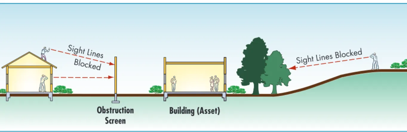
5.6.6 siGht LiNes
The siting of the building should carefully consider what can be ob-served from areas beyond the project’s control. The design should maximize opportunities for internal surveillance of site perimeters and screening of internal areas from external observation. Topography, rel-ative elevation, walls, and fences are design elements that can open and close views. Vegetation can also open or block views, not only for secu-rity purposes but also to provide beauty and support way-finding. As a rule of thumb, vegetation should be very high or low, to keep views open. Vegetation at the base of buildings and structures should be de-signed and maintained to prevent people – or explosives – from being hidden from view.
Building form, placement, and landscaping inherently define the “lines of sight” in a space, and management of the threat of hostile surveil-lance is a consideration in the protection of people, property, and operations. Denying aggressors a “line of sight” to a potential target, either from on or off site, increases the ability to protect sensitive
infor-Figure 5-19: Trees and screens block sight lines into the site.
SOURCE: U.S. aIR FORCE, installation force protection guide
Depending on the circumstances, landforms such as berms can be either beneficial or detrimental to anti-surveillance. Elevated sites may enhance surveillance of the surrounding area from inside the facility, but may also allow observation of on-site areas by adversaries. Buildings should not be sited immediately adjacent to higher surrounding terrain; unsecured buildings owned by unfamiliar parties; or vegetation, drainage channels, ditches, ridges, or culverts that can provide concealment.
For high-risk buildings, it may be necessary to provide additional protec-tion by creating a clear zone immediately adjacent to the structure that is free of all visual obstructions or landscaping that might hide packages (Figure 5-20). Thus only very low or high planting may be admissible.
Figure 5-18:
Building exposed to view from high adjacent building; screen blocks view out from protected building.
The clear zone facilitates monitoring of the immediate vicinity and visual detection of attack (and the approach of everyday criminals). Walkways and other circulation features within a clear zone should be located so that buildings do not block views of pedestrians and vehicles. If clear zones are implemented, it may be necessary to implement other anti-sur-veillance measures.
Figure 5-20:
Clear zone with unobstructed views.
SOURCE: U.S. aIR FORCE, installation entry control facilities design guide
5.7
siGNAGe
s
igns for vehicular and pedestrian circulation are an important element of security. They can clarify entries and routes for pedes-trians, staff, visitors, deliveries, and service, each with differing functional objectives and security requirements to be satisfied. Signage can be designed to keep intruders out of restricted areas, but inadequate signage can create confusion and defeat its primary purpose. Confusion over site circulation, parking, and entrance locations can contribute to a loss of site security. Unless required, signs should not identify sensitive areas. Signs should be vprovided off-site and at entrances.m Traffic regulatory and directional signs that control traffic flow and
direct vehicles to specific appropriate points.
m Consideration of use of street addresses or building numbers instead
of detailed descriptive information inside the site.
m Minimization of the number of signs identifying high-risk buildings. m Location of clear warning signs to ensure that possible intruders are
aware of restricted entry areas.
m Minimization of signs identifying critical utility complexes (e.g., power
plants and water treatment plants).
m Post clear signs to minimize accidental entry by unauthorized
personnel into critical asset areas.
m Location of bilingual (or more) warning signs should be used in areas
where two or more languages are commonly spoken. The wording on the signs should denote warning of a restricted area. The signs should be posted at intervals of no more than 100 feet and should not be mounted on fences equipped with intrusion-detection equipment. Additionally, the warning signs should be posted at all entrances to limited, controlled and exclusion areas.
m Location of variable message signs that give information on special
events and visitors far inside site perimeters.
5.8
pArKiNG
p
arking is the transitional interface between vehicular and pedes-trian systems. These areas must be designed to accommodate both modes of transportation, safely, effectively, and in keeping with the overall site design strategy.There are five characteristic methods of providing parking spaces for staff, visitors, residents, and others:
m Public on-street parking lanes m Surface parking lots
m Free-standing parking structures m Underground parking structures m Parking within occupied buildings
Parking on open sites is typically accommodated by surface parking lots and/or parking structures. Parking within buildings or in underground parking structures is common in the central business district and is dis-cussed in Chapter 6, Section 6.7. On-street parking lanes may occur on any site but are particularly characteristic of urban areas and are also dis-cussed in Chapter 6.
All parking in an open site should preferrably be located outside the stand-off zone for high-risk buildings. Control may be necessary at the entry parking in non-exclusive zones for regulation and fee collection. If the site has a perimeter barrier, authorization to enter the site and any necessary inspection can take place at entry control points, minimizing the need for additional control at parking structures.
For high and moderate risk structures warning signs that are easy to un-derstand should be installed along the physical barriers and at each entry. An important design goal is the development of an efficient layout of the parking spaces and provision of an internal circulation that has clear paths for pedestrians and vehicles. Parking restrictions can help to keep potential threats away from a building. Operational measures may also be necessary to inspect or screen vehicles entering parking areas.
The following considerations may help designers to implement sound parking measures for buildings that may be at high risk:
m Only permit parking by inspected vehicles within the stand-off zones
and avoid or limit drop-off zones.
m Provide appropriate setback from parking to the protected building.
Structural hardening may be required if the stand-off is insufficient. In new designs, it may be possible to adjust the location of the building on the site to provide adequate setback from adjacent properties.
m If possible, locate unexpected visitor or general public parking near,
but not on, the site itself, or outside the stand-off zone.
m Locate vehicle parking away from high-risk buildings to minimize
collateral blast effects from potential vehicle bombs.
m Locate parking within view of occupied buildings. Use carefully
chosen plantings around parking structures and parking lots to permit observation of pedestrians while at the same time reducing the visual impact of automobiles. Topography, existing conditions, or aesthetic objectives may make this difficult or undesirable to achieve, and closed-circuit TV surveillance cameras may substituted.
m For all stand-alone, above ground parking structures, maximize
visibility for surveillance into, out of, and across the garage.
m Do not permit uninspected vehicles to park within the exclusive zone
or in the second layer of defense. Parking within the building is highly undesirable, but if it cannot be avoided the following restrictions may be applied:
m Visitor parking with ID check
m Company vehicles and employees of the building only m Employees or visitors with special needs, e.g. handicapped m Proper credentials for all passengers and full vehicle
inspection
m Restrict parking between individual buildings.
m When establishing parking areas, provide emergency communication
systems (e.g., intercom, telephones, etc.) at readily identified, well-lighted, closed-circuit television-monitored locations to permit direct contact with security personnel.
m Provide parking lots with closed-circuit television cameras connected
to the security system and adequate lighting capable of displaying and videotaping lot activity.
In parking structures the following should be avoided:
m Employ express or non-parking ramps, sending the user to parking on
flat surfaces.
5.9
LoADiNG DocKs AND serVice
Access
L
oading docks and service access areas are commonly required for buildings and are typically desired to be kept as invisible as pos-sible. For this reason, special attention should be devoted to these service areas in order to avoid undesirable intruders. Designers should give consideration to the following:m Provide for screening in an inspection area, either off-site or a
significant distance away from the loading dock, before permitting entrance to the loading dock.
m Separate (by at least 50 feet) loading docks and shipping and receiving
areas in any direction from utility rooms, utility mains, and service entrances, including electrical, telephone/data, fire detection/alarm systems, fire suppression water mains, cooling and heating mains, etc.
m Avoid having driveways within or under buildings.
m Provide signage to clearly mark separate entries for deliveries m Significant structural damage to the walls and ceiling of the loading
dock may be tolerable as long as the areas adjacent to the loading dock do not experience severe structural damage or collapse. This can be achieved by the provision of adequate structural design that limits damage to the loading dock area and allows explosive forces to vent to the building exterior. The floor of the loading dock does not need to be designed for blast resistance if the area below is not occupied and/ or does not contain critical utilities.
5.10 physicAL security LiGhtiNG
s
ecurity lighting should be provided for overall site, building, and perimeter illumination to allow security personnel to maintain vi-sual-assessment during darkness. It may provide both a real and psychological deterrent for continuous or periodic observation. Lighting is relatively inexpensive to maintain and may decrease the need forsecu-At entry control points, a minimum surface lighting average of 4 hori-zontal foot-candles will help ensure adequate lighting for pedestrians, islands, and guards. Where practical, high-mast lighting is recommended, because it gives a broader, more natural light distribution, requires fewer poles (less hazardous to the driver), and is more aesthetically pleasing than standard lighting. Lighting of the entry control point should give drivers a clear view of the gatehouse and, for security personnel, a clear view of vehicles in the area.
The type of site lighting system used depends on the overall requirements of the site and the building. Four types of lighting are used for security lighting systems:
m Continuous lighting is the most common security lighting system.
It consists of a series of fixed lights arranged to flood a given area continuously during darkness with overlapping cones of light. Two primary methods of using continuous lighting are glare projection and controlled lighting:
m The glare projection security lighting method lights the area
surrounding a controlled area with high-intensity lighting. It is a strong deterrent to a potential intruder because it makes him or her very visible, while making it difficult to see inside the secure area. Guards are protected by being kept in comparative darkness while being able to observe intruders at a considerable distance. This method should not be used when the glare of lights directed across the surrounding territory could annoy or interfere with adjacent operations.
m Controlled lighting is best when there are limits to the
lighted area outside the perimeter, such as along highways. In controlled lighting, the width of the lighted strip is controlled and adjusted to fit the particular need. This method of lighting may illuminate or silhouette security personnel.
m Standby lighting has a layout similar to continuous lighting; however,
the lights are not continuously lit, but are either automatically or manually turned on when suspicious activity is detected or suspected by security personnel or alarm systems.
m Movable lighting consists of manually operated, movable searchlights
that may be lit during hours of darkness or as needed. The system normally is used to supplement continuous or standby lighting. Movable lighting is also used to assist in vehicle inspection in temporary and permanent vehicle inspection areas.
m Emergency lighting is a backup power system of lighting that may
duplicate any or all of the above systems. Its use is limited to times of power failure or other emergencies that render the normal system inoperative. It depends on an alternative power source, such as
installed or portable generators or batteries. Emergency backup power for security lighting should be considered.
5.11 chemicAL, BioLoGicAL, AND
rADioLoGicAL issues
A
major concern is the vulnerability of buildings to CBR threats. The following discussion is limited to those aspects of pro-tection against CBR that concern site design and building placement. Issues relating to urban sites are covered in Chapter 6, Sec-tion 6.10. A more complete outline of the nature of the CBR threat and the protective measures and actions to safeguard buildings is provided in FEMA 426, Reference Manual to Mitigate Terrorist Attacks Against Buildings, Chapter 5, Sections 5.1-5.7.The main protective measures against CBR are:
m Evacuation
m Sheltering in place
m Air filtration and pressurization m Exhaustion and purging
m Personal protective equipment
Of these measures, evacuation may affect planning for a large open site because of provisions needed for assembly and staging. Provision for shel-tering in place is an aspect of building design, while air filshel-tering and exhaustion are related to the building heating, ventilating and cooling (HVAC) system. Because in the urban situation, air intakes may be
situ-ated adjacent to a public sidewalk, location and protection of intakes is important. Personal protection refers to equipment such as respirators, escape hoods, CBR detectors, decontamination equipment, etc., which would be used by trained personnel.
Hazards that originate outdoors are typically less severe than airborne hazards that originate indoors. Even without special protective systems, buildings can provide protection in varying degrees against airborne haz-ards that originate outdoors. For indoor hazhaz-ards, the building HVAC systems are of particular concern because they can become an entry point and distribution system for contaminants. Because buildings allow only a limited exchange of air between indoors and outdoors, not only can higher concentrations occur when there is a release inside, but hazards may also persist longer indoors.
Three aspects of site planning and design have a bearing on CBR protection:
m Placement and orientation of a new building should take into account
prevailing winds, although the actual wind direction and speed at the time of an outdoor release will directly affect the building.
m The surrounding terrain may result in channeling a CBR release
towards the site and building.
m Building elevation is relevant, because heavier-than-air contaminants
will have greater impacts upon low-lying areas, as the agent hugs the ground as it disperses. Thus, since most CBR agents are heavier than air, raising air intakes on buildings is the most beneficial action to take. Lighter-than-air CBR agents would be of greater concern if the
pre-vailing wind directed the agent to the air intakes (in a similar manner to reflected blast pressure on the face of a building), and the air intakes pulled the agent into the building because the HVAC equipment was still operating. Placing the air intakes on the side away from the prevailing wind should reduce the agent uptake into the building, since the wind clears the agent around the building and the intakes are somewhere sheltered against the wind.
5.11.1 stAGiNG AreAs for cBr eVAcuAtioN
A CBR event may be such that no building occupants are affected or contaminated, but it is necessary to evacuate the building to prevent possible spread and to decontaminate affected areas. Following a CBR event that results in casualties (injuries or deaths) it is imperative that ev-eryone who is in the building be decontaminated for medical treatment, whether on-site or in a hospital, so that ambulances will not require ex-tensive decontamination later.
For the latter type of building evacuation, it is important to designate as-sembly and staging areas where personnel should gather after evacuation. Pre-event planning should designate, if possible, four assembly points (one for each side of the building, so that wind conditions can be
accom-modated). After the attack, the assembly area should be selected. A head count should be taken, and a method for accounting for non-employees, such as visitors and suppliers, should also be established.
The assembly and staging areas must accommodate a number of func-tions. Some of the characteristics and requirements of a staging area are noted below. A full description of the procedures involved after an attack and the requirements for the staging area are provided in FEMA 453, Safe Rooms and Shelters, Protecting People Against Terrorist Attacks, Sections 1-9
and 1-10. The following is a brief outline of some of the considerations. The assembly area is divided into three containment zones:
m Hot Zone – the area where the agent or contaminant is in high
concentration and high exposure, typically an ellipse or cone extending downwind from the release.
m Warm Zone – the area where the agent or contaminant is in low
concentration or minimal exposure, typically a half circle in the above-wind direction.
m Cold Zone – those areas outside the hot and warm zones that have not
been exposed to the agent or contaminant.
Figure 5-21 shows the characteristics of an assembly area capable of dealing with a large-scale event, perhaps occurring on a large campus-type site. Some consideration should be given in the site planning and design for how such an area would be accommodated. In this diagram, the dimensions shown are illustrative only and would vary for the nature and size of the event, the number of casualties, and the topography and size of the site. After a CBR attack, occupants leaving a shelter must go through several
staging areas to ensure that any CBR contamination not be spread across a larger geographical area. To control the potential spread of a CBR agent and ensure the safety of the victims and first responders, several staging areas and designated entry and access points for three key zones would be established. These are:
m Patients staging area (PSA). The PSA is located in the cold zone and
is the transfer point for victims who have been stabilized for transport to higher care medical facilities or for fatalities to be transported to
m Safe refuge area (SRA). The SRA is located in the warm zone and
is used to assemble survivors and witnesses who are not injured and will require minimal medical attention and decontamination. Law enforcement and FBI agents can conduct interviews and gather evidence at the SRA.
Figure 5-21 also shows the location of the casualty collection point (CCP). The CCP is located in the warm zone and will typically have three pro-cessing stations, as shown in Figure 5-21.
Figure 5-21:
Containment zones and staging areas.
5.12 iNfrAstructure AND site
utiLities
In-ground infrastructure can be any of the following:
m Standard utility lifelines such as water, gas, steam, sewer, storm water,
electric communications, etc.
m Any structure that can be used by persons, such as subway tunnels,
stations, large sewer or water tunnels, or pipes.
m Ventilation shafts supplying either the building or the in-ground
infrastructure.
These infrastructure systems should be protected at the site level, where they support operations, buildings, their occupants, and other assets. These systems have vulnerability throughout the three layers of defense, in the public or private rights-of-way (ROW), at the entries to and within the property, and at the entry to the building.
Failure of part of the on-site infrastructure, such as tunnels and utility cor-ridors that are in close proximity or attached to the building, may impact the structural system, and the failure of one system may initiate failure of the other.
At the outset of design, it is important to identify accurately how close the utility lines are to the building and how far (vertically and horizontally) they are in-ground or above ground.
Following are key issues in relation to site utilities and infrastructure.
m Based upon the size of a lifeline, such as a large sewer system, access
to the site or building may be possible and, based on the size of the utility service entrance to the building, intruders or CBR agents may be able to enter the building. Large entrances should be secured against unauthorized access.
m On-site infrastructure may be connected to the building by
m Redundant sources of supply and any on-site storage needs, e.g., water
storage (for domestic and industrial use or fire suppression), fuel storage, and on-site generators, should be identified. Each utility system’s requirements for siting, redundancy, and safety should be addressed.
m Transformers and switchgear should be protected and secured with
fences or protective structures. Utility areas in non-exclusive zones (such as water sources, transformer banks, commercial power and fuel
connections, and heating and power plants) are often required to have perimeter barriers for health and safety reasons; these barriers may need to be enhanced for high-risk security locations.
m All utility penetrations of a site’s perimeter barrier, including
penetrations in fences, walls, or other perimeter structures, should be sealed or secured to eliminate openings large enough for persons to pass through the barrier. Typical penetrations could be for storm sewers, water, electricity, or other site utility services.
m If access is required for maintenance of utilities, penetrations should
be secured with screening, grating, latticework, or other similar devices so that openings do not allow intruder access. Provide intrusion detection sensors and consider overt or covert visual surveillance systems, if warranted by the sensitivity of assets requiring protection.
m Protect drainage ditches, culverts, vents, ducts, and other openings
that pass through a perimeter and that have a cross-sectional area greater than 96 square inches and whose smallest dimension is greater than 6 inches by securely fastened welded bar grilles. As an alternative, drainage structures may be constructed of multiple pipes, with each pipe having a diameter of 10 inches or less. Multiple pipes of this diameter may also be placed and secured in the inflow end of a drainage culvert to prevent intrusion into the area. Ensure that any addition of grills or pipes to culverts or other drainage structures be coordinated with the engineers, so that they can compensate for the diminished flow capacity and additional maintenance that will result from the installation.
m Secure manhole covers 10 inches or more in diameter. They may be
secured with locks and hasps, by welding them shut, or by appropriate bolting to their frames. Ensure that hasps, locks, and bolts are made of materials that resist corrosion. Keyed bolts (which make removal by unauthorized personnel more difficult) are also available. If very high security is required, manhole covers that resist shattering after being artificially “frozen” by an aggressor should be considered.
m .Prepare vulnerability assessments for all utility services to the
site, including all utility lines, storm sewers, gas transmission lines, electricity transmission lines, and other utilities that may cross the site perimeter.
m Locate on-site petroleum, oil, and lubricant storage tanks and
operations buildings down slope from all other buildings. Site fuel tanks at an elevation lower than operational buildings or utility plants. Locate fuel storage tanks at least 100 feet from buildings.
m Provide on-site utility systems that support site security, life safety, and
rescue functions with redundant or loop service, particularly in the case of electrical systems. Where more than one source or service is not currently available, provisions should be made for future connections.
m Where redundant utilities are required in accordance with other
requirements or criteria, ensure that they are not collocated or do not run in the same chases. This minimizes the possibility that both sets of utilities will be adversely affected by a single event.
m Decentralize a site’s communications resources when possible;
the use of multiple communications networks will strengthen the communications system’s ability to withstand the effects of a terrorist attack.
m Where emergency backup systems are required, ensure that they are
located away from the systems components for which they provide backup.
5.13 LANDscApiNG – pLANt seLectioN
AND DesiGN
Landscape design uses a palette of living materials that respond to sea-sonal changes in climate and change in size and mass over time. (Figure 5-22).
Following are some considerations for the use of planting for security,
m When a living landscape is installed with a security function, it
needs to be well maintained to support its continued health and effectiveness.
m Planting can be effectively used to soften and enhance the sometimes
stark appearance of barrier walls, planters, and other security elements (Figures 5-23, 5-24).
Figure 5-22:
Plant materials can provide shading for buildings, parking, walkways, and outdoor use areas; bring enhancement to buildings and plazas; and mark the seasons with their varied colors and forms.
m Planting can be used as a perimeter barrier in the form of thorny
hedges and dense hedgerows. However, this approach is not always acceptable to security specialists due to the potential for plants to die, and possible maintenance problems versus the greater permanence of structural solutions.
Choice of plant material with the ultimate size and maintenance
Figure 5-23:
Use of planting to soften and enhance the appearance of walls and other security elements at the Seattle Courthouse.
SOURCE: PETER WaLKER aND PaRTNERS Figure 5-24:
Use of planting in conjunction with perimeter barriers, Seattle Courthouse.
SOURCE: PETER WaLKER aND PaRTNERS
m Conflicts may occur between planting areas and underground utilities.
Below-ground conditions should be accurately identified before landscape design is commenced; understand underground conditions to avoid potential problems (Figure 5-26).
Figure 5-25:
Planting design with high foliage to keep ground level sight lines open but close off other sight lines into building.
SOURCE: NCPC
Figure 5-26: Relationship between security elements and underground conditions.
5.14 coNcLusioN
A
ddressing security as an integral part of site design helps to maintain the character of the site and enhance its relationship to the surrounding neighborhood. Careful building placement and acknowledgment of the importance of sight lines will help to ensure a successful design.It is important to treat security design as a piece of a larger urban plan for the site. By incorporating security features that serve more than one purpose, the design can enhance the everyday security at the site while protecting against possible terrorist activity.
The layers of defense provide a logical structure for design development, influencing patterns of circulation and selection of plant materials and fostering creative lighting techniques to form a functional, aesthetic, and secure site.